HAL Id: hal-01629867
https://hal.archives-ouvertes.fr/hal-01629867
Submitted on 6 Nov 2017HAL is a multi-disciplinary open access archive for the deposit and dissemination of sci-entific research documents, whether they are pub-lished or not. The documents may come from teaching and research institutions in France or abroad, or from public or private research centers.
L’archive ouverte pluridisciplinaire HAL, est destinée au dépôt et à la diffusion de documents scientifiques de niveau recherche, publiés ou non, émanant des établissements d’enseignement et de recherche français ou étrangers, des laboratoires publics ou privés.
Electrical resistivity monitoring of a SiC/[Si-B-C]
composite under oxidizing environments
Coraline Simon, Francis Rebillat, Gérald Camus
To cite this version:
Coraline Simon, Francis Rebillat, Gérald Camus. Electrical resistivity monitoring of a SiC/[Si-B-C] composite under oxidizing environments. Acta Materialia, Elsevier, 2017, 132, pp.586 - 597. �10.1016/j.actamat.2017.04.070�. �hal-01629867�
1
Electrical resistivity monitoring of a SiC/[Si-B-C]
composite under oxidizing environments
Coraline Simona,b, Francis Rebillata, Gérald Camusa
a
Laboratoire des Composites Thermostructuraux, (CNRS-CEA-SAFRAN), University of Bordeaux, 3 allée de la Boétie, 33600 Pessac, France
b
SAFRAN Ceramics, Rue Toussaint Catros, 33187 Le Haillan, France
Abstract.
The introduction of Ceramic Matrix Composites parts in civil aeronautics requires a thorough understanding of their evolution under the oxidizing environments presentwithin the engines. In this respect, a SiCf/PyC/[Si-B-C]m material has been tested in fatigue at
450°C and 100 MPa (which is a typical stress during take-off) under two types of
environmental conditions: ambient air, and moist air with an imposed water pressure of 10
kPa. Static fatigue and cyclic fatigue at a frequency of 1 Hz were both performed with these
two conditions. As expected, the additional presence of moisture contributes to increase the
degradation of the mechanical properties of the material, leading to shorter lifetimes and
higher increases in electrical resistivity. It is shown that the pyrocarbon interphases are the
main electrical conductors in this material: the electrical resistance can therefore be an
accurate indicator of the damage state of these interphases, which are sensitive to the
oxidizing environment. The global resistance increase presents two distinct phases of
evolution in the four tests performed, with a transition around 35-40% of the time to failure. A
model is proposed to account for this global resistance change, which proves to be in good
agreement with experimental results. Moreover, the evolution of the electrical resistivity
2
fiber/matrix interfaces which are critical for mechanical properties. Finally, electrical
resistance monitoring seems to provide information on the damage state of the material
complementary to acoustic emission results, allowing an unprecedented assessment of the
evolution of the interphases state during ageing under oxidizing environments.
Keywords: Ceramic Matrix Composites (CMCs); Electrical resistivity; Thermo-mechanical
ageing; Oxidizing environment
1. Introduction
SiC/SiC based Ceramic Matrix Composite materials are promising materials for applications
in high-temperature jet engines due to their excellent thermo-mechanical properties under
oxidizing environments (high strength, toughness and creep resistance) [1-5]. Their
introduction in aeronautical engines should enhance the thrust efficiency by reducing weights
and increasing the possible service temperatures. The engine parts which are aimed at being
made of CMC materials are submitted to highly oxidizing environments, with high
temperatures and relatively high pressures of oxidizing species (O2, H2O). Yet, it is
well-known that matrix cracking and accompanying debonding and sliding are the main damage
modes encountered by these composites, giving access for the oxidizing species to the most
critical constituents, fibers and interphases, and hence severely reducing their mechanical
properties [6-10]. As CMCs are intended to be used in critical structural parts in the engine,
safety is a key concern and the ability to monitor damage accumulation is therefore required.
Most conventional non-destructive evaluation techniques (NDE), such as acousto-ultrasonic,
X-ray or thermography, (i) require that the components should be taken out of service for long
durations, and (ii) are more efficient for the detection of out-of-plane flaws (such as those
3
observed in fiber-reinforced composites submitted to in-plane loadings. Acoustic emission
(AE) has proved to be an interesting technique for quantifying matrix cracking as well as
predicting times to failure [11-13]. However, it cannot be used as an inspection technique at
regular time intervals, since damage has to be recorded when it takes place. Moreover, almost
no AE activity is recorded during creep tests, which involve crack opening and/or
viscoplasticity of one of the constituents (most often the fibers in the case of CMC materials).
The measurement of the change in the electrical resistance of the material (ER) is a
particularly promising way of monitoring matrix transverse cracking. This technique has
already proved to be pertinent in following the onset and propagation of damage for various
materials such as carbon fiber-reinforced polymer composites (CFRP) [14-15], particle
reinforced polymer composites [16], and civil engineering materials [17]. CFRP materials
have been widely studied, since their electrical resistance is very sensitive to fiber breakage
(carbon fibers are a good electrical conductor unlike the polymeric matrix), which is one of
the main damage modes in on-axis tension. ER monitoring during room-temperature fatigue
tests has been investigated [14, 18], leading for some materials to fatigue life prediction
criteria [19]. Recently, the idea of extending the four-probe methods to several pairs of
strategically located leads has led to bi-dimensional ER mapping of damage [20], which
opens a great field of potential applications. Regarding SiCf/SiCm composites, since both the
fibers and the matrix are relatively good electrical conductors, their ER has thus proved to be
very sensitive to matrix cracking for both CVI (Chemical Vapor Infiltration) and MI
(Melt-Infiltration) materials [21], as well as to interlaminar crack growth [22]. High-temperature
tests have been monitored using ER measurements with adapted lead locations, which led to
the observation that ER increases during creep testing at 1315°C on CVI materials [23].
4
displaying a higher rate of increase slightly before failure [24]. All the SiCf / SiCm materials
tested in the previously mentioned studies were processed with a boron nitride interphase,
which is a poor electrical conductor compared to other composite constituents. The SiCf /
[Si-B-C]m material considered in the present work is the same that in a previous paper focusing
on room-temperature damage monitoring and electro-mechanical modeling [25]. This
material has a pyrocarbon interphase, which is a high electrical conductor, and should
therefore give access to different damage modes.
As previously described, these composites are designed for applications in oxidizing
environments, and carbon is known to be very sensitive to oxidation. Hence, it is proposed in
the present work to monitor in real time the ER change of SiCf / PyC / [Si-B-C]m samples
submitted to fatigue and creep tests under oxidizing environments. It should be pointed out
that very few studies have been published regarding fatigue tests in oxidizing conditions with
real-time ER measurement. Such a study has only been performed on SiC-coated
carbon/carbon composites [26], highlighting a strong influence of oxidation-related damages
on the ER of the samples. If the damage mechanisms are of course different in a SiCf / PyC /
[Si-B-C]m composite, this yet tends to confirm that ER could be very sensitive to both
mechanical and thermo-chemical related damage in the considered material.
2. Experimental materials and methods
Sustained load tests and cyclic fatigue tests (further referred to as static and cyclic fatigue
tests, respectively) have been performed on a Nicalon NL207 SiC fiber-reinforced composite
produced by SAFRAN Ceramics referred to as Cerasep® A40C. The fibers were woven in an
interlock pattern, with 52% of the fibers orientated in the warp direction and 48% in the weft
5
matrix, these fibers were coated with a pyrocarbon interphase. The matrix is composed of
both ex-polymer SiC (PIP) and CVI layers based on the [Si-B-C] system, with self-healing
properties. A self-healing [Si-B-C] seal-coat was finally deposited on the surface of the
samples to protect them from oxidizing environments.
Glass fiber-reinforced epoxy tabs were glued on dog-bone shape specimens of a length of 200
mm orientated according to the warp direction, in order to electrically insulate the composite
specimens from the testing system. An extensometer (25 mm) with alumina rods was placed
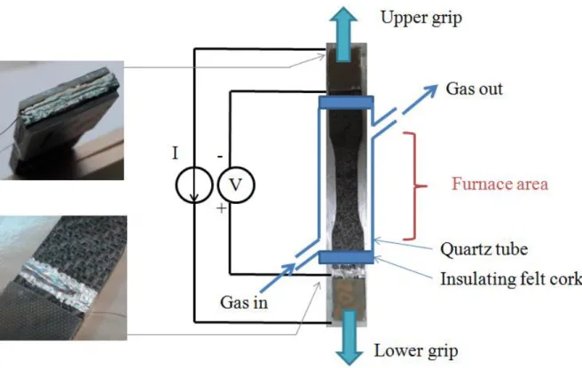
on the edge of each specimen. Tests under ambient air were performed on an Instron 8501
machine equipped with a resistive furnace; tests under moist air were performed on another
Instron machine (8861, lamp furnace) fitted with a system of environment control, which
allows to send a gas flow along the sample placed into a quartz tube.
The selected moist atmosphere is composed of N2/O2/H2O: 70/20/10 with a total flow of 110
NL/h (or a gas rate in cold zone of 5 cm/s). A fraction of the oxygen and nitrogen flows
through a heated water tank and an automatic system of solenoid valves regulates the
percentage of dry gas and wet gas in order to finally have the requested dew point of 46°C
(corresponding to 10 kPa of water pressure). This controlled gas mixture is then sent along the
sample in the furnace and confined within the quartz tube. Regarding the tests under ambient
air, the atmosphere was not controlled but the air humidity content was recorded, showing
that the ambient water pressure was 1 kPa with very small variations.
Electrical resistance (ER) was measured using a four-point probe method in order to minimize
contact resistance Two types of connection were used to fix the conductive wires to the
specimen. Two rings were first painted around the specimen with silver conductive varnish
(130 mm apart), in order to collect the surface current on the whole perimeter of the sample
6
grooves were machined in the edges at the extremities of the sample so that the outer wires
could be set in the right place, and then fixed using CW conductive epoxy. This method,
similar to the one described in [23], allows the wire to be in contact not only with the
seal-coat but also with the inner fibers and interphase.
A constant direct current was applied through the outer wires whereas the associated voltage
was measured between the inner wires. A power supply (AOIP PJ6301) provided a current of
10mA, and a voltmeter (Agilent 34970A) measured the induced voltage. Electrical resistance
was measured using this system with an accuracy of 0.5 mΩ. The stability of the measure has
been checked during 40h once the sample was fixed in the hydraulic jaws and submitted to
the selected test temperature (450°C) without any loading being applied.
Acoustic emission signals were additionally recorded, using a MISTRAS Group SA system,
equipped with two PICO sensors placed symmetrically on the grips. Data was acquired at a
rate of 2 MHz, and the detection threshold was fixed to 50 dB.
Four different tests were performed up to failure, all of them at 450°C and with a maximal
stress of 100 MPa applied within the warp direction, on specimens issued from the same
production batch. The test temperature of 450°C was chosen because it is critical for the
considered material and leads to the shortest lifetimes: the self-healing process is not efficient
(the oxidation kinetics of boron-containing phases are too slow), while the oxidation of the
carbon interphase is active. Besides, the selected stress and temperature conditions are typical
values at which the material would be submitted during service within the considered part.
Two of those tests were carried out under ambient air (P(H2O) ≈ 1 kPa): sample SA (Static
Ambient) was submitted to sustained loading (i.e. static fatigue), and sample CA (Cyclic
Ambient) to cyclic fatigue with a frequency of 1 Hz between 40 MPa and 100 MPa (i.e.
7
the same mechanical conditions, leading to samples called SM (Static Moist air) and CM
(Cyclic Moist air). In order to facilitate comparisons between obtained results, the two types
of atmospheres present the same oxygen partial pressure (20 kPa). Characterization
unloading-reloading cycles were regularly interposed at a speed of 47MPa/ min. Regarding
the cyclic fatigue tests, the fatigue cycles were interrupted at the mid-cycling stress (70 MPa),
the sample was then loaded up to 100 MPa, unloaded to 0 MPa, reloaded to 100 MPa, and
unloaded down to the stress of 70 MPa at which the fatigue cycles were again performed.
Conversely, regarding static fatigue, the sample was simply unloaded from 100 MPa to 0
MPa, and then reloaded back to 100 MPa. The mechanical loading was applied at high
temperature, after 4h of stabilization at 450°C.
3. Results
3.1 General observations
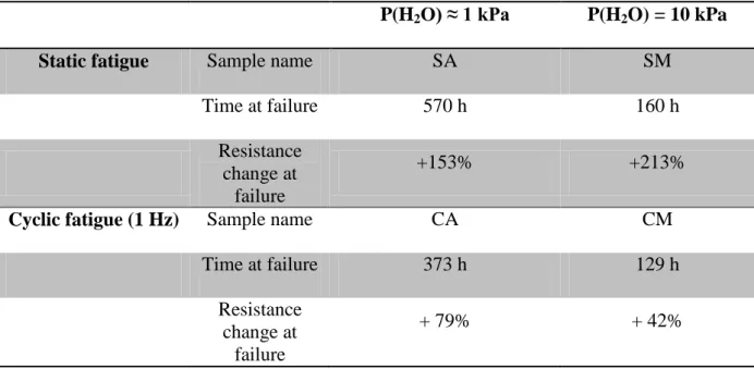
Obtained results in terms of lifetimes and percentage of resistance change at failure are
summarized in Table 1 for the four different tested samples.
When considering the testing conditions of sample SA, it clearly appears that it was submitted
to the less drastic conditions. As a matter of fact, one may point out that: (i) the time to
failure is reduced by a factor close to 3 when P(H2O) is increased from 1 to 10 kPa, for both
mechanical conditions and (ii) cyclic fatigue appears to be more severe than static fatigue
since the time to failure is divided by 1.5 under ambient air and 1.25 under moist air.
3.2
Global resistance change
The changes in electrical resistivity at failure are significant (up to +213% for sample SM)
8
temperature [25]. In this last case, the resistance increased by only 1% at 100 MPa and 42% at
failure (occurring at 257 MPa).
All the evolutions in electrical resistivity observed throughout the duration of the tests are
plotted on Fig. 2a under a normalized form equal to , where R0 is the initial
zero-load stabilized resistance at 450°C and in the atmosphere of the test, and R is the real-time
measured resistance under loading.
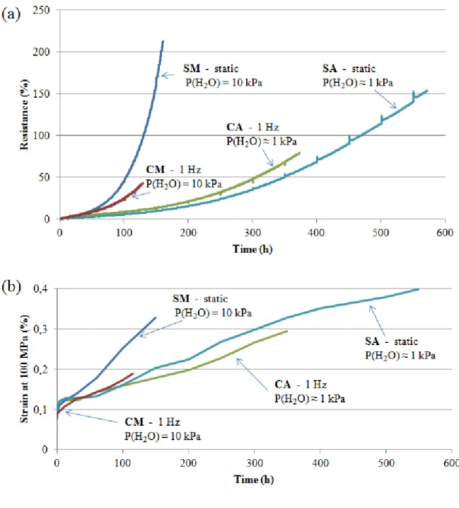
For the four tests, the resistance increases quite slowly and almost linearly at first, before
increasing more quickly, at a starting time which depends on the test conditions. A clear
difference appears between the tests performed under a water pressure of 10 kPa and the ones
performed under a water pressure of 1 kPa: the resistance increases much quicker with the
highest rate of moisture, regardless of the imposed mechanical conditions. Furthermore,
taking the SA test as reference (static / 1 kPa H2O), the change of mechanical conditions from
static to cyclic fatigue (CA) slightly increases the resistance change at a given time (as a
combination of oxidation and mechanical effects); the change of environmental conditions to
10 kPa of water (SM) has a clearly more pronounced effect, with a rapid and elevated increase
in resistance.
Sample CM which has been submitted to cyclic fatigue under moist air presents a surprisingly
low increase in relative resistance as compared to sample SM: in the same moist atmosphere,
cyclic fatigue leads to a shorter lifetime than creep at the maximum stress, but to a smaller
increase in resistance. This observation will be discussed in Section 4.1.
The evolutions of the strain measured at the maximum stress of 100 MPa (Fig. 2b) reveal a
higher strain increase for sample SM than for the samples tested in other conditions, similarly
9
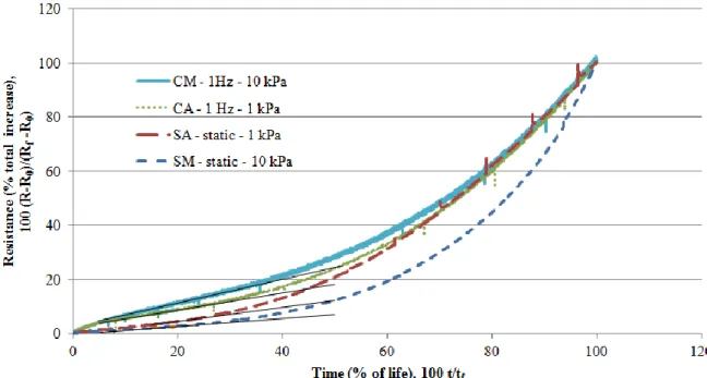
These results are also displayed in another normalized scale on Fig. 3, in terms of the
percentage of total resistance increase as a function of. the percentage of sample life (where Rf
and tf stand for the resistance at fracture and the time to fracture, respectively). This graph
clearly reveals a transition in the evolution of each sample. The four tests, after an initial
transitional period, display a linear phase followed by a stronger nonlinear increase in
resistance. Interestingly, it appears that the transition between these two phases occurs at
similar percentages of lifetime (35-40%) for the four tests. This observation, not visible on the
strain evolutions (Fig. 2b), could be of great interest if one has to quickly estimate the time at
failure of a material in given conditions.
3.3
ER evolution during unloading-reloading cycles
In addition to the persistent increase in resistance always observed for all the samples, it can
be fruitful to focus on the evolution of the electrical resistance during the interposed
quasi-static unloading-reloading cycles, usually aimed at recording the Young’s modulus of the
studied sample. At the beginning of the tests, as expected, the resistance decreases upon
unloading (the cracks are closing and the current has therefore more connections through the
material) and it increases again upon reloading (the cracks are re-opening). However, the
shape of the stress-resistance cycles rapidly deviates from this "normal" behavior: for sample
CM (cyclic fatigue in moist air), after a few hours, the resistance unexpectedly starts to
increases during unloading from 100 MPa to 60 MPa before decreasing again until complete
unloading (Fig. 4). Conversely, upon reloading, the resistance increases until about 80 MPa,
and then decreases between 80 MPa and 100 MPa to almost reach the initial value at which
unloading was proceeded (at least for the first 10 to 20 hours of ageing treatment). This point
will be explained later. This phenomenon seems to be amplified as the duration of ageing is
10
opening of the upper part (for which the resistance increases) also appears to be increasingly
more pronounced.
Conversely, below 40 MPa, the stress-resistance cycles present a regular evolution, with the
change in curvature starting just above this level of stress. This should obviously be linked to
the cyclic fatigue performed with a R ratio of 0.4, i.e. between 40 MPa and 100 MPa , which
is precisely the range of stress for which the resistance displays an unexpected behavior.
Indeed, the quasi-static unloading-reloading cycles between 0 and 100 MPa are interposed
among fatigue cycles (1 Hz) between 40 and 100 MPa, which means the sample is most of the
time not in the stress regime below 40 MPa. This will be further discussed in Section 4.2.
The other test performed under the same conditions, but in ambient air (sample CA), presents
a similar behavior (Fig. 5). The evolution of resistance below 40 MPa is very regular whereas,
above this value, a reverse curvature is also exhibited, becoming increasingly pronounced.
After 200h or more of ageing treatment, the value reached once the characterization cycle has
been completed becomes increasingly higher than it was initially. The stresses at which the
maxima of resistance are reached are almost independent of the duration of ageing: about
55-60 MPa during unloading, and 80-85 MPa during reloading. It should be noted that this
reverse curvature phenomenon is absolutely not visible on the stress-strain loops (Fig. 5b).
Regarding static fatigue, one may observe a different behavior during the characterization
cycles for the two tests which were performed (cf. Fig. 6 with the example of sample SA). At
60h, the resistance evolves regularly with a similar behavior during unloading and reloading
but, starting from 150h, it exhibits a higher value than the one it had before the cycle was
interposed. If, upon reloading, the resistance always increases monotonously, conversely,
during unloading at 250h, it remains constant until about 60 MPa but then decreases while the
11
and more upon unloading up to 550h where it increases monotonously during unloading as
well as during reloading. The stress-strain hysteretic loops (Fig. 6b) present a classical shape,
though with a maximum strain reached after reloading being lower than the one before
unloading. This has to be linked with the mentioned higher resistance value after the cycle.
Sample SM exhibits the same type of behavior than sample SA, but with an alteration in
reversibility reached after shorter durations (the state presented at 250h for sample SA on Fig.
6 is reached at 100h for sample SM).
It can then be clearly inferred that the phenomenon of reverse curvature presented on Fig. 4
and Fig. 5 is linked to cyclic fatigue conditions. Further interpretations will also be detailed in
the Section 4.2.
4. Discussion
4.1 Global resistance increase
As already mentioned, the changes in resistance at failure are significantly higher than with
previous results obtained on the same composite tested in tension at room temperature [25].
Yet, in this later case, the final crack density was certainly greater than during the fatigue tests
performed in the present study with a maximum stress of 100 MPa (respectively, during
fatigue tests, the absolute energy of acoustic emission remains at a much lower level, around
maximum 40% of that to the ultimate tensile stress). Thereby, the fact that this higher crack
density led to smaller increases in resistance means that other mechanisms contribute to the
observed resistance changes.
Since it was previously demonstrated that in the considered Cerasep® A40C composite, the
12
orders of magnitude as compared to the other constituents (fibers, and [Si-B-C]-CVI matrix)
taking into account their representative content in the composite, a change in the global
resistance of the material has to be related to an alteration the carbon interphase. This
alteration has been previously linked to damaging phenomena, i.e. matrix microcracking and
related debonding and sliding. Hence, one has to evoke damaging phenomena specifically
taking place during cyclic tests and long time exposure to oxidizing environments such as
mechanical wear on one hand and oxidation on the other hand.
Indeed, during cyclic fatigue tests, at each unload/reload cycle, the friction between the
various interfaces (matrix/interphase, interphase/fiber, between interphase carbon planes) can
damage the organization of the pyrocarbon planes within the interphase, and therefore lead to
the increase of their resistivity. Moreover, when the cracks reach the fiber tows, they can
become paths for oxidizing species leading to a progressive consumption of the carbon
interphases, which in turn increases the global resistance of the sample.
This last mechanism appears to be predominant since the two tests performed under a moist
atmosphere (10 kPa of water, 20 kPa of O2 is maintained) and therefore more oxidizing
environment have led to quicker and greater increases in resistance after a same duration of
fatigue exposure (Fig. 2a). The oxidizing species in a large excess may be less consumed by
oxidation close to the sample surface and hence diffuse deeper inside the material bulk. This
can be confirmed by the SEM observation of the fracture surface of sample SA (Fig. 7), on
which the interphases have completely disappeared because of oxidation (a gap which is not
present on the pristine material is visible between fiber and matrix). During static tests, the
times before failure are greater than for cyclic fatigue tests, and the cracks are more open, so
the oxidation of the interphases is made easier. Indeed, the increases in resistance at failure
13
Taking, as already mentioned, the static test performed under ambient air as a reference test, a
change in the environment (from 1 to 10 kPa of water pressure, i.e. from SA to SM) has a
greater influence than a change in the mechanical conditions (from static fatigue to cyclic
fatigue, i.e. from SA to CA). The cyclic CA test presents a slightly higher increase in
resistance compared to the static SA test, which can be related to a supplementary damage
due to mechanical wear in addition to the one due to oxidation. However, regarding the tests
performed under a controlled moist atmosphere, the static test presents a higher ER increase
than the cyclic test. This could mean that for low levels of moisture (i.e. 1 kPa), the
mechanical conditions have a predominant influence on the damage of the electrical contacts
within the material (typically linked to the pyrocarbon interphase). Conversely, for higher
levels of moisture (i.e. 10 kPa), the impediment of electrical conductivity is mostly due to the
atmosphere (oxidation of pyrocarbon): under static fatigue, the oxidizing species have an
easier access to the bulk of the material, which leads to a faster increase of the electrical
resistance.
Figure 3 shows that the global resistance changes of the four tests present first a phase of
linear evolution until 35-40% of the time to failure, followed by a phase of nonlinear increase
at a higher rate. This must result from a modification and/or an evolution of the main damage
mode during the fatigue test, allowing the access of oxidizing species deeper inside the bulk
material [27-28]. Indeed, it has been shown that, already for a single crack, once the oxidation
of the matrix constituents close to the surface takes place, the quantity of diffusing oxygen
toward the interphase increases. This acceleration of oxygen diffusion is enhanced with the
increase of the partial pressure of the oxidizing species and the opening of the crack.
A tensile test interrupted at 100 MPa has been performed on the studied material. The
polished cross-sections showed that there were cracks in the seal-coat and in the inter-tow
14
not reach the fiber tows at the beginning of the fatigue tests, the oxidizing species do not
reach the interphase of the longitudinal fibers which mainly carry the current. The slow linear
increase in ER at the beginning of the tests could hence be linked to both mechanical wear in
the interphases and oxidation of small amounts of carbon present in the seal-coat. Then, after
an ageing duration depending on the test conditions, the cracks propagate enough to reach the
longitudinal fiber tows, giving access to the oxidizing species towards the interphases of the
longitudinal fibers, and therefore increasing the rate of change of the ER signal. The transition
between these two phases seems to occur around 35 to 40% of the time to failure for the four
different testing conditions. As this transition can be directly determined during the test (by
setting a given percentage of deviation from the linear evolution), this could be a rather easy
way to have an estimation of the time to failure at about 40% of the test duration.
Therefore, the measurement of the electrical resistance of the material can provide a real-time
monitoring of the damage state of the interphases, which are the key constituent regarding the
mechanical properties of the composite [29].
4.2
ER evolution during unloading-reloading cycles
As detailed in section 3.3, the electrical resistance tends to have a non-monotonic evolution
during the unloading-reloading cycles interposed under quasi-static conditions. A
phenomenon of reverse curvature is observed after a few hours during all the cyclic fatigue
tests, with a maximum resistance reached at a non-maximum stress for both unloading and
reloading phases (Fig. 4). The maximum resistance is always reached at about the same level
of stress for cycles performed at various times, i.e. around 60 MPa during unloading and
around 80 MPa during reloading. Moreover, the resistance values below 40 MPa seem
unaffected by this reverse curvature and display a regular monotonic evolution. Therefore,
15
of 70 MPa) appear to have a significant influence on the ER evolution during the cycles. At
stresses which are not reached during the cyclic fatigue, the ER evolution is unaffected: the
debonded fiber/matrix interface is submitted to sliding along its whole length whereas sliding
only occurs along a shorter length, around the matrix crack, during cyclic fatigue. One may
think that only a fraction of the debonded interfaces generated by the initial loading at 100
MPa are then submitted to mechanical wear and oxidation. Shortly after reaching the
mid-stress value of 70 MPa (i.e. slightly under this value for unloading and slightly above for
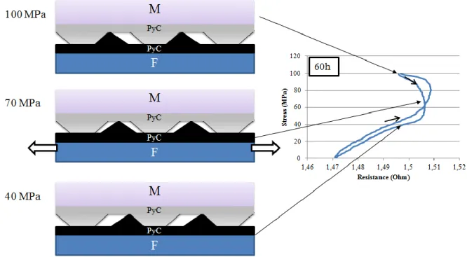
reloading), the resistance reaches its maximum level. A scenario can be proposed to explain
these correlations (Fig. 8): if, during cyclic fatigue, mechanical wear affects a fraction of the
various interfaces of the composites (fiber/interphase, interphase/matrix, intra-interphase)
then, the softest part can be worn out between the positions related to minimum and
maximum stress (i.e. between 40 and 100 MPa).
Hence, at the intermediate position of 70 MPa, the hardest part stands at the middle of the
generated cavity, with a loss of electrical contacts and therefore an increased resistance. When
the stress reaches the lowest value of 40 MPa the extremities of the generated cavity are again
connected, which decreases the resistance. Between 40 MPa and zero load, i.e. once
connections have been recovered, crack closure accounts for the regular decrease in ER.
During reloading, the resistance is maximum when the middle position with minimum
contacts is reached, at a stress slightly above 70 MPa because of friction. Then, getting closer
to 100 MPa, electrical contacts are formed again, and the resistance decreases.The maximum
ER is reached for different stress levels during unloading and reloading because of friction
and hysteresis effects: the same relative position within the interfaces is reached slightly under
70 MPa during unloading and slightly above 70 MPa during reloading.
This mechanism being qualitatively described, it is then possible to define indicators in order
16
the amplitude of the reverse curvatures evolve during the ageing of the samples. Several indicators can be analyzed, such as the “resistive modulus”, defined as the stress/resistance slope at low levels of stresses, by analogy with the mechanical modulus. Initially very high
(because of the low dependence of ER on stress), it quickly drops, as the application of the
same stress leads to higher resistance increases. It is proposed to focus on the difference
between the maximum resistance (reached during either unloading and reloading) and the
residual resistance at zero stress, therefore defining two indicators Iunload and Ireload (Fig. 9a
and 9b).
These indicators may be linked to a “resistive modulus” (or more precisely the inverse of a modulus) introduced by analogy with the mechanical Young’s modulus, since the maxima in
resistance are always more or less reached at the same stress (they are related to the slope of
the Stress-Resistance curve). Iunload and Ireload can be evaluated for each time at which a
characterization unloading-reloading cycle was performed and their evolution as a function of
time is plotted in Fig. 9c for sample CM and in Fig. 9d for sample CA. For these two tests, the
curves thus obtained follow a surprisingly similar pattern with three phases: initial increase,
steady state phase, final increase. At the beginning of the tests, Iunload and Ireload have low
values in relation with the level of damage in the material which is also low: the resistance is
almost not modified between 0 and 100 MPa. Then with the increasing level of damage
(development of matrix cracking, debond lengths and cracks opening), the resistance of the
sample becomes more sensitive to the applied stress. These three phases of evolution could be
compared to creep behavior, with an initial transitory phase, a steady evolution and, finally,
an acceleration of damage.
The times of transition between phases are very different for the two tests (20h-60h for CM,
60h-200h for CA), but it is really worth mentioning that the percentages of time to failure are
17
Hence, it appears that the increase in water pressure (the only different condition between the
two tests) has accelerated the damage of the sample in terms of resistive modulus, but the
mechanisms involved have not been modified. Such a consistent evolution of resistive
modulus could be of great interest for life prediction if a transition could be accurately
identified as soon as 15% of the time to failure
Regarding static fatigue tests, no reverse curvature has been ever observed with the ER
evolutions upon reloading (Fig. 6), which supports the assumption that this phenomenon
closely linked to cyclic loading. The evolution of the shape of the cycles displayed in Fig. 6
can be explained as follows: between each characterization cycle, performed every 50h after
100h of ageing, the sample is then left with the same applied stress without any disruption
during these 50 hours. It can therefore stabilize in this steady state during which it undergoes
micro-electrical contacts linked to micro-welding helped by the fluid oxide generated by the
self-healing matrix at 450°C. During unloading, these micro-contacts are broken, which tends
to increase the resistance whereas, during reloading, they are not generated again because this
is a time-dependant process (hence the ER increases as well). This mechanism is amplified
with the level of damage of the material.
The analysis of the evolution of ER during unloading-reloading cycles can provide significant
information regarding mechanisms occurring inside the bulk of the material, within
micro-interfaces. The interpretations described here still need further confirmation by tests
performed in different conditions, yet these indicators could have a high potential regarding
life prediction.
4.3 Modeling approach for the global resistance evolution
The global evolution of ER during the four fatigue tests seems to be ruled by the same
18
test conditions. It therefore appears possible to build a model which would quantitatively
estimate the change in ER evolution induced by a change of testing conditions, especially
regarding the water pressure which was proved to greatly influence the global ER evolution.
For more clarity, all the following equations involve resistance instead of specific resistance,
which does not constitute a drawback in the present study since the tested samples all present
the same geometry. However, the model can be easily adapted to specific resistances if one
wishes to apply it to samples of various geometries.
As demonstrated in [25], the change in ER in the Cerasep® A40C composite can be described
by the following equation:
(1) In Eq. 1, is the difference between the electrical resistance measured at strain ε and the initial resistance R0 (which is the stabilized resistance at the test temperature
for high temperature tests), Ld is the debond density (sum of all debonded lengths of the
sample), is the transverse matrix crack density, α and K are two coefficients to be
determined (respectively linked to the piezo-resistance factor of pyrocarbon and to the
damage related increase in resistivity).
During the fatigue tests of this study with a maximal stress of 100 MPa, the strains are
relatively low (maximum strain around 0.3%). Hence, Eq. 2 can be considered as a first order
approximation, where A is a coefficient of proportionality.
(2)
It has been shown that the transverse matrix crack density is directly related to the cumulative
energy of the acoustic emission signal [30-31]. This energy, recorded during the two static
19
test up to the failure of the specimen. Hence, it can be assumed that the transverse matrix
crack density remains constant after the initial damage of the specimen (i.e. only debonding is
aimed at progressing). Equation (2) can then also be written again as follows, with A’ another
coefficient of proportionality:
(3)
With these assumptions at hand, the increase in resistance then appears to be directly
proportional to an increase in the debond density.
As described in 4.1, it is assumed that after a phase of linear increase in ER linked to the
development of the micro-crack network generated within the seal-coat, the micro-cracks start
to develop within the fiber tows. From that moment, the oxidizing species present in the
environment have an access to the pyrocarbon interphase deposited on the fibers, which is
very sensitive to oxidation. As the transverse matrix crack density is assumed to be constant
(no increase in acoustic energy), the crack does not propagate within the tow, and the
progression of degradation of the interphase is mainly ruled by oxidation mechanisms. When
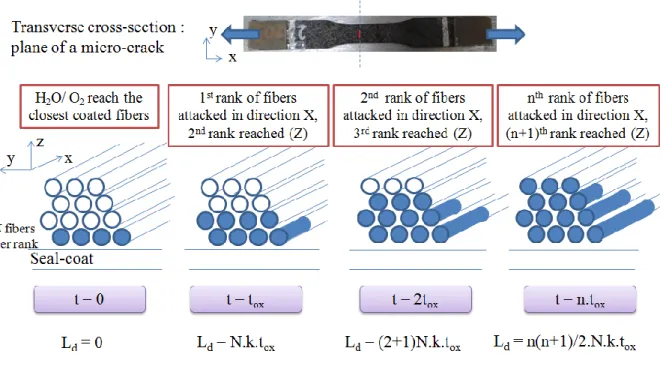
considering a transverse cross-section within the plane (y,z) (i.e. the plane of the
micro-cracks), it appears that the oxidizing species would first attack the fibers closest to the
seal-coat (Fig. 10). Oxidation then progresses (i) towards the bulk of the material and the next rank
of fibers, from an interphase to another close interphase (z direction) and (ii) along the same
longitudinal fibers following the damaged interphase (x longitudinal direction). As the
oxidation of carbon is active, with the formation of CO2 gas, the kinetics of the reaction can
be considered as linear (no passivation layer is generated and the diffusion limitation of O2
may be considered as negligible through the narrow opened pathway by oxidation since the
oxidation kinetic rate (or quantity of O2 consumed as a function of time) is very slow at such a
20
explain the observed ER evolutions as a function of the environmental conditions. Therefore,
for a single longitudinal fiber cut by a crack, the debond length ld can be expressed by Eq. 4,
with a linear kinetic rate k.
(4)
Similarly, always assuming an active oxidation with generation of gas, the time required to
oxidize the next rank of fiber towards the bulk of the material in the Z direction can be
considered as constant (tox). This duration depends on k and on a characteristic distance l0
which is an average distance between two ranks of fibers:
(5)
Hence, the progression of oxidation can be schematized as depicted in Fig. 10. The initial
time t=0 is taken when the oxidizing species first reach the closest fibers. After tox, the first
rank of fibers is oxidized ( for each of these fibers) which leads to a global debond density (sum of all debond lengths) of (as there are N fibers in a rank).
After 2 tox, the second rank is oxidized as well; meanwhile, the interphases along the
longitudinal fibers of the first rank have been attacked. Each of the fiber reached by the
oxidizing species, whatever its rank, has developed a debond length during an additional duration tox (between t = tox and t = 2tox) which leads to a global debond density of
. Next, at t = 3 tox, the third rank is oxidized, the second rank fibers
have a debond length of and the first rank fibers are debonded over
since they have been submitted to oxidation during a duration of 3tox. The global debond
density hence increases to . Similarly, at t = n tox, the nth rank
of fibers is oxidized and the debond density reaches the value expressed in Eq. 6.
21
Introducing the change of variable , Eq. 6 can easily be turned into Eq 7 as follows:
(7) In order to assess the influence of the pressure of oxidizing species on Ld, the linear kinetic
rate k can be expressed as a function of oxygen and water pressures, and their associated
orders :
(8)
The combination of Eqs. 5, 7 and 8 can lead to a new formulation of Ld :
(9) This theoretical approach can now be compared to the experimental observations. First, the
polished transverse cross-section of sample SM (static fatigue, moist air) presented in Fig. 11
is in close agreement with the mechanism schematically depicted in Fig. 10. Indeed, the fibers
closest to the surface are heavily oxidized, and the damaged zones progress towards the bulk
of the material over around four fiber tows.
Moreover, in order to assess Eq. 9, the change in ER is plotted in Fig. 12 as a function of the
square of the time, and linear regressions are presented for the last part of the evolution,
which should be linear according to the model described above. This point is evidenced by the
following equation obtained by reporting Eq.9 into Eq.3, revealing a quasi linear behavior as
soon as tox is very small comparatively to t.
22
It appears that for three of the four performed test (CM, SA, CA), an excellent linear fit is
achieved, which strongly supports the proposed model.
Considering a single micro-crack, it appears from Fig. 10 that the progression of oxidation
would be affected by several discontinuities, when reaching a different fiber tow. However,
because of the high number of micro-cracks and of the various positions of fiber tows linked
to the weaving, this effect is average and does not appear on the overall increase in resistance.
The penetration rate of the oxidation front is most likely slightly higher under cyclic fatigue
(CA) than under static fatigue (SA) because of a more important wear-related interface
degradation.
In order to further assess the model, an analysis of the parabolic coefficient γ given by can be performed (with γ proportional to ). It
is proposed to compare the γ coefficients obtained from the tests CA (cyclic, ambient air) and
CM (cyclic, moist air) for which the only difference is the water pressure. As P(O2) is
identical for these two tests, Eq.9 gives the following theoretical ratio between the two γ
coefficients : (10)
The reactive order associated to water pressure in the oxidation of carbon has been evaluated
to m=0.31 in [32] for similar composites. Hence, a theoretical γ ratio can be estimated:
(11)
This ratio can directly be compared to the linear coefficients issuing from the regressions
23
(12)
The estimated theoretical ratio and the experimental one are very close, which strongly
supports the theoretical global approach previously described. Regarding the SM test (static
fatigue, moist air), the ER increase is actually closer to be depending on t3 rather than t². The parabolic evolution issuing basically from a bidimensional propagation of oxidation, it could
be inferred that for sample SM, submitted to the most extreme conditions regarding oxidation
(highly moist air with open cracks), the oxidation progresses as well in a third direction (y
direction), represented on Fig. 13. With a high increase of the oxidized lengths, a limitation by
oxygen diffusion may also be involved in the advance of the oxidation front.
5. Conclusion
Four ageing tests have been performed to failure with a maximum stress of 100 MPa and
under various mechanical and environmental conditions: static fatigue (also referred to as
creep if viscoplasticity is involved) or cyclic fatigue at 1 Hz, ambient air (1 kPa of water) or
moist air (10 kPa of water). The electrical resistance of the samples was continuously
recorded during the ageing tests using a four-point probe method. A higher level of moisture
in the environment has led to shorter life durations as well as to faster increases in resistance.
The following conclusions can be highlighted :
(i) The increase in ER can be directly linked to damage of the pyrocarbon interphase
in the considered composite. ER monitoring can therefore give real-time
information on the level of damage of the interphase, which is a key constituent in
the mechanical properties of CMCs.
(ii) The evolution of ER follows a similar pattern for the four different test conditions,
24
these four performed tests, the transition between these two phases occurs between
35 and 40% of the time to failure. This observation could have a great potential
regarding lifetime estimation.
(iii) The analysis of the evolution of ER during quasi-static unloading-reloading cycles
can give access to phenomena occurring within interfaces situated in the bulk of
the material, besides difficult to be reached with other monitoring techniques. The
dependence on damage of ER evolution during cycles requires further
investigation, but could be of great value as it seems to follow similar sequences
with different characteristic times for different test conditions.
(iv) A theoretical approach has been proposed regarding the evolution of the global
increase in resistance. It has been linked to the progression of oxidation from the
seal-coat to the bulk in both the longitudinal X direction and through the thickness
(Z direction), with a rate depending on the environmental conditions. The model
has proved to be in good agreement with experimental data for 3 of the 4
performed tests, and an explanation has been suggested for the fourth one.
Electrical resistance was shown to be a very valuable monitoring technique regarding ageing
tests in oxidizing environments. The combinated effects of the mechanical and oxidation
damage on the interphase and consequently on the ER should be investigated further, as well
as the evolution of ER during the unloading-reloading loops, which seems really promising
but not fully understood yet. The study of relationships between electrical resistance
evolutions and strain evolutions could also be helpful to point out the effects of mechanical
damage sequences on electrical changes in CMCs. Further efforts regarding modeling and an
enhanced understanding of the phases of evolution of ER could possibly allow this monitoring
25
Acknowledgements
This work was supported by SAFRAN Ceramics, mainly through a PhD scholarship provided
to Coraline Simon. The authors would like to sincerely thank Dr. G.N. Morscher (University
of Akron) for the fruitful discussions they have had together. They want as well to gratefully
acknowledge Vincent Herb (Safran Ceramics) and Bruno Humez (LCTS).
References
[1] R. Naslain, Design, preparation and properties of non-oxide CMCs for application in engines and nuclear reactors: an overview, Composites Science and Technology 64 (2004) 155–170.
[2] F. Christin, Design, fabrication, and application of thermostructural composites like C/C, C/SiC, and SiC/SiC composites, Advanced Engineering Materials 4 [12] (2002) 903-912.
[3] E. Bouillon, P. Spriet, G. Habarou, C. Louchet, T. Arnold, G. Ojard, D. Feindel, C. Logan, K. Rogers, D. Stetson, Engine test and post engine test characterization of self-sealing ceramic matrix composites for nozzle applications in gas turbine engines, Proc. ASME TURBO EXPO 2004: Power for Land, Sea and Air, Vienna, Austria (2004) GT-2004-53976.
[4] J. C. Cavalier, I. Berdoyes, E. Bouillon, Composites in Aerospace Industry, Advances in Science and Technology 50 (2006) 153-162.
[5] A. Lacombe, P. Spriet, A. Allaria, E. Bouillon, G. Habarou, Ceramic matrix composites to make breakthroughs in aircraft engine performance, 50th AIAA Conference, Palm Spring, CA, USA (2009) 119-SDM-75.
[6] F. Rebillat, Advances in self-healing ceramic matrix composites, in: I.M. Low (Ed), Advances in ceramic matrix composites, Woodhead Publishing, Cambridge, 2014, pp. 369-409.
[7] F. Lamouroux, S. Bertrand, R. Pailler, R. Naslain, M.Cataldi, Oxidation-resistant carbon-fiber-reinforced ceramic-matrix composites, Composites Science and Technology 59 (1999) 1073-1085.
[8] J.A. DiCarlo, H.M. Yun, J.B. Hurst, Fracture mechanisms for SiC fibers and SiC/SiC composites under stress-rupture conditions at high temperatures, Applied Mathematics and Computation 152 (2004) 473-481.
[9] W.H. Glime, J.D. Cawley, Oxidation of carbon fibers and films in ceramic matrix composites: a weak link process, Carbon 33 [8] (1995) 1053-1060.
[10] L. Casas, J.M. Martinez-Esnaola, Modelling the effect of oxidation on the creep behavior of fibre-reinforced ceramic matrix composites, Acta Materiala 51 (2003) 3745-3757.
26
[11] G.N. Morscher, Stress-dependent matrix cracking in 2D woven SiC-fiber reinforced melt-infiltrated SiC matrix composites, Composites Science and Technology 64 (2004) 1311–1319.
[12] E. Maillet, N. Godin, M. R’Mili, P. Reynaud, J. Lamon, G. Fantozzi, Analysis of acoustic emission energy release during static fatigue tests at intermediate temperatures on ceramic matrix composites: towards rupture time prediction, Composites Science and Technology 72 (2012) 1001-1007.
[13] M. Moevus, D. Rouby, N. Godin, M. R’Mili, P. Reynaud, G. Fantozzi, G. Farizy, Analysis of damage mechanisms and associated acoustic emission in two SiC/[Si–B–C] composites exhibiting different tensile behaviours. Part I: Damage patterns and acoustic emission activity, Composites Science and Technology 68 (2008) 1250-1257.
[14] K. Schulte, C. Baron, Load and failure analyses of CFRP laminates by means of electrical resistivity measurements, Composites Science and technology 36 (1989) 63-76.
[15] J. Wen, Z. Xia, F. Choy, Damage detection of carbon fiber reinforced polymer composites via electrical resistance measurement, Composites: Part B 42 (2011) 77-86.
[16] G.R. Ruschau, S. Yoshikawa, R.E. Newnham, Resistivities of conductive composites, J. Appl. Phys. 72 (1992) 953.
[17] R. Ranade, J. Zhang, J. P. Lynch, V. C. Li, Influence of micro-cracking on the composite resistivity of engineered cementitious composites, Cement and Concrete Research 58 (2014) 1-12.
[18] I. De Baere, W. Van Paepegem, J. Degrieck, Electrical resistance measurement for in situ monitoring of fatigue of carbon fabric composites, International Journal of Fatigue 32 (2010) 197-207.
[19] A. Vavouliotis, A. Paipetis, V. Kostopoulos, On the fatigue life prediction of CFRP laminates using the Electrical Resistance Change method, Composites Science and Technology 71 (2011) 630-642.
[20] D.-J. Kwon, P.-S. Shin, J.-H., Kim, K. L. DeVries, J.-M. Park, Evaluation of dispersion and damage sensing of carbon fiber polypropylene (PP)-polyamide (PA) composites using 2 dimensional electrical resistance mapping, Composites: Part A 90 (2016) 417-423.
[21] C.E. Smith, G.N. Morscher, Z. Xia, Monitoring damage accumulation in CMCs using electrical resistivity, Scripta Materialia 59 (2008) 463-466.
[22] R. Mansour, E. Maillet, G.N. Morscher, Monitoring interlaminar crack growth in ceramic matrix composites using electrical resistance, Scripta Materialia 98 (2015) 9-12.
[23] C.E. Smith, G.N. Morscher, Z. Xia, Electrical resistance as a Nondestructive Evaluation Technique For SiC/SiC CMC under creep-rupture loading, Int. J. Appl. Ceram. Technol. 8 (2011) 298-307.
[24] Z. Han, G.N. Morscher, E. Maillet, M. Kannan, S.R. Choi, F. Abdi, Electrical resistance and acoustic emission during fatigue testing of pristine and high velocity
27
impact SiC/SiC composites at room and elevated temperature, Proceedings of the ASME Turbo Expo 2016, GT2016-56507, Seoul, South Korea.
[25] C. Simon, F. Rebillat, V. Herb, G. Camus, Monitoring damage evolution of SiC/[Si-B-C] composites using electrical resistivity: crack density-based electromechanical modeling, Acta Materialia 124 (2017) 579-587.
[26] C. Liu, L. Cheng, X. Luan, H. Mei, High-temperature fatigue behavior of SiC-coated carbon/carbon composites in oxidizing atmospheres, Journal of the European Ceramic Society 29 (2009) 481-487.
[27] F. Rebillat, Advances in Self-Healing CMCs, in: I.M. Low (Ed.), Advances in Ceramic Matrix Composites, Woodhead Publishing, Composites Science and Engineering: Number 45, IBSN 978-0-85709-120-8, 2014, pp. 369-398.
[28] C. Simon, G. Camus, F. Bouillon, F. Rebillat, Modeling of simultaneous oxidation and volatilization phenomena along a crack in a self-healing multi-constituent material, submitted to Oxidation of Metals (2016).
[29] A.G. Evans, F.W.Zok, J. Davis, The role of interfaces in fiber-reinforced brittle matrix composites, Composites Science and Technology 42 (1991) 3-24.
[30] G.N. Morscher, Modal acoustic emission of damage accumulation in a woven SiC/SiC composite, Compos. Sci. Technol. 59 (1999) 687–697.
[31] G.N. Morscher, Stress-dependent matrix cracking in 2D woven SiC-fiber reinforced melt-infiltrated SiC matrix composites, Compos. Sci. Technol. 64 (2004) 1311–1319.
[32] X. Bertran, Oxidation behavior of a 2D Carbon/Carbon composite for structural applications between 150 and 400°C in civil aviation, PhD thesis, University of Bordeaux (2013).
28
Figures
Figure 1 - Specimen configuration with electrical leads, the tube confining the gas flow and the furnace area.
29
Figure 2 – (a) Relative electrical resistance change as a function of time for the 4 tests performed at 450°C and (b) evolution of strain (measured at the maximum stress 100 MPa) as a function of time for the same 4 tests.
30
Figure 3 - Resistance change in terms of the percentage of total resistance increase as a function of the percentage of sample life for the 4 tests performed at 450°C.
Figure 4 - Changes in resistance observed at the beginning of the test upon interposed unloading-reloading cycles after various durations of ageing (sample CM, cyclic fatigue at 1 Hz, humid air: P(H2O) ≈10 kPa).
31
Figure 5- (a) Resistance as a function of stress and (b) stress as a function of time during unloading - reloading cycles after various durations of ageing (sample CA, cyclic fatigue, ambient air: P(H2O) ≈ 1 kPa).
Figure 6 – (a) Resistance as a function of stress and (b) stress as a function of time during unloading - reloading cycles after various durations of ageing (sample SA, static fatigue, ambient air: P(H2O) ≈ 1 kPa).
32
Figure 7 - SEM image of the break surface and absence of interphase between fiber and matrix for sample SA.
Figure 8 - Schematic representation of the fiber/matrix interfaces for various stresses, and link with the measured resistance at these stresses.
33
Figure 9 - (a) Definition of Rres and Rmax for unloading and reloading phases on the cycle
performed after 100h during test CA, (b) Definition of the indicators Iunload and Ireload, (c)
evolution of Iunload and Ireload during test CM, (d) evolution of Iunload and Ireload during test CA.
Figure 10 – Schematic evolution of the transverse cross-section in the plane of a micro-crack (Dark zones on fibers are zones where the interphase is oxidized).
34
Figure 11- Micrography of a transverse cross-section of sample SM (bottom edge: surface of the sample).
Figure 12 – Evolution of ER as a function of the square of time for four ageing tests, and related linear regressions.
35
Figure 13 - Schematic representation of the progression of oxidation in a third direction (y direction) adapted to sample SM.
Table 1 - Name, time at failure and resistance change at failure for the four tested samples according to the mechanical and environmental conditions (at atmospheric pressure with a constant partial pressure of oxygen 20 kPa) to which they were submitted
P(H2O) ≈ 1 kPa P(H2O) = 10 kPa
Static fatigue Sample name SA SM
Time at failure 570 h 160 h
Resistance change at
failure
+153% +213%
Cyclic fatigue (1 Hz) Sample name CA CM
Time at failure 373 h 129 h
Resistance change at
failure