HAL Id: emse-00837514
https://hal-emse.ccsd.cnrs.fr/emse-00837514
Submitted on 24 Feb 2014
HAL is a multi-disciplinary open access
archive for the deposit and dissemination of
sci-entific research documents, whether they are
pub-lished or not. The documents may come from
teaching and research institutions in France or
abroad, or from public or private research centers.
L’archive ouverte pluridisciplinaire HAL, est
destinée au dépôt et à la diffusion de documents
scientifiques de niveau recherche, publiés ou non,
émanant des établissements d’enseignement et de
recherche français ou étrangers, des laboratoires
publics ou privés.
Electromagnetic glitch on the AES round counter
Amine Dehbaoui, Amir-Pasha Mirbaha, Nicolas Moro, Jean-Max Dutertre,
Assia Tria
To cite this version:
Amine Dehbaoui, Amir-Pasha Mirbaha, Nicolas Moro, Jean-Max Dutertre, Assia Tria.
Electromag-netic glitch on the AES round counter. Fourth International Workshop on Constructive Side-Channel
Analysis and Secure Design - COSADE’2013, Mar 2013, Paris, France. pp 17-31,
�10.1007/978-3-642-40026-1�. �emse-00837514�
Electromagnetic Glitch
on the AES Round Counter
Amine Dehbaoui1, Amir-Pasha Mirbaha2, Nicolas Moro1,
Jean-Max Dutertre2 and Assia Tria1
1 cea-leti
2 Ecole nationale sup´erieure des Mines de Saint-´´ Etienne [email protected]
D´epartement sas - Syst`emes et Architectures S´ecuris´es Centre Micro´electronique de Provence-Georges Charpak
880 Avenue de Mimet, f-13541 Gardanne, France
Abstract. This article presents a Round Addition Analysis on a soft-ware implementation of the Advanced Encryption Standard (aes) algo-rithm. The round keys are computed on-the-fly during each encryption. A non-invasive transient fault injection is achieved on the aes round counter. The attack is performed by injecting a very short electromag-netic glitch on a 32-bit microcontroller based on the arm Cortex-M3 pro-cessor. Using this experimental setup, we are able to disrupt the round counter increment at the end of the penultimate round and execute one additional round. This faulty execution enables us to recover the en-cryption key with only two pairs of corresponding correct and faulty ciphertexts.
1
Introduction
A fault in a cryptographic system refers to an accidental or an intentional distur-bance that causes the encryption process to deviate from its correct execution or result. In this case, the cryptographic system may act abnormally or the result of encryption (or decryption) may be incorrect, considered as faulty.
The first alert about the feasibility of using faults to break cryptosystems was reported by D. Boneh et al. in [7]. A Fault Attack consists in using hardware malfunction to infer secrets from the target’s faulty behavior or output. The fault injection can be performed by various physical perturbation techniques, as reported in [5]. The first structured method for exploiting the secrets from faulty encryptions was presented as Differential Fault Analysis (dfa) in [6]. Since
The final publication is available at Springer via http://dx.doi.org/10.1007/978-3-642-40026-1 2
then, more analysis methods have been developed to reveal secrets from faulty behavior or outputs.
Among different perturbation methods, creating strong electromagnetic (em) disturbances on the top of a circuit is a practical way to induce faults. J.-J. Quisquater and D. Samyde reported in [15] the possibility of an em fault injection into the transistors and into the memory cells of a smart-card circuit. Afterwards, other research, e.g. [17] and [9], reported further successful em fault attacks on cryptosystems.
In this paper, we introduce a new round addition attack induced by Electro-Magnetic Glitch (emg) injection on an up-to-date microcontroller running an aes algorithm. The resulting erroneous ciphertexts are then processed in order to retrieve the secret key. This process involves cryptanalysis and differentiation techniques often used by the dfa.
This article is organized as follows: emg fault injection is briefly presented in section 2. Then, the experimental setup, describing the targeted microcontroller and the em attack bench, is presented in section 3. A quick reminder on the aes is given in section 4. It is followed by the state-of-the-art of Round Modification Analysisand the proposed Round Addition attack. The experiment outline and the corresponding cryptanalysis are described in section 5. To conclude, our findings are summarized in section 6 with further perspective.
2
Electromagnetic Glitch Injection Technique
Non-invasive fault injection techniques, such as emg, represent a serious threat to the security of cryptographic circuits. They are sometimes considered as more dangerous than semi-invasive or invasive techniques because they do not require any chip decapsulation proficiency and equipment.
Choukri et al. showed in [8] the possibility of using power glitches to reduce the number of rounds of an aes implementation. Kim et al. also used power glitches in [11] to skip subroutine calls in a software rsa-crt implementation. Similarly, Schmidt et al. [16] prevented a subroutine call in a square-and-multiply rsasoftware implementation. More recently Balasch et. al [4] performed a study of the clock glitch effects on a 8-bit avr microcontroller. They showed that instructions can be replaced or skipped by injecting a clock glitch, and that the effects of faults are deterministic and reproducible. More precisely, as the clock period decreases, a larger number of the opcode’s bits are stuck at zero.
The efficiency of emg is mainly due to the inner properties of electromag-netic waves. Their ability to propagate through different materials is the most interesting one since it allows an attacker (without any preliminary preparation of the chip) to induce a very short glitch in the power supply voltage. This short glitch in the power supply voltage is the result of a coupling mechanism between the coil antenna and the targeted chip’s Power Ground Network (pgn) [14,9].
In comparison with power glitch, emg technique allows the attacker to target a small part of the internal pgn by choosing an accurate xyz stage and a small
antenna diameter. A study about the emg localized effect is presented in [9]. As reported by the authors, the propagation delays are increased through the circuit’s logic when the emg is injected on top of the die surface. Thus, by the violation of the circuit’s timing constraints, the operations are not accomplished during the expected time and faults appear.
According to previous experiments in [9] on a basic 8-bit avr microcontroller, an emg induces faults during the program execution. A careful analysis of the faulty behavior, revealed that they were due to an instruction skip at the instant of the emg injection. To the best of our knowledge, no emg fault injection has been reported on an up-to-date 32-bit microcontroller. This fault model seems to be very threatening, since the opponent may be able to skip or to prevent a subroutine call, just by an emg injection.
3
Practical Electromagnetic Glitch Setup
As described in section 2, emg technique can be used to avoid the execution of an instruction on a microcontroller. In this section, the emg injection setup used to generate transient em pulses is described.
3.1 EMG Platform
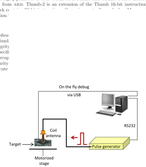
The emg platform depicted in Figure 1 is composed of a control computer, the target device, a motorized stage, a pulse generator, and a magnetic antenna. The target (described in subsection 3.2) is mounted on the xyz motorized stage. The computer controls both the pulse generator (through a rs-232 link) and the target board (through a usb link).
The pulse generator is used to deliver voltage pulses to the magnetic coil. It has a constant rise and fall transition time of 2ns. The amplitude range tively the width) of the generated pulses extends from -200V to 200V (respec-tively from 10ns to 200ns). We use a magnetic antenna composed of a few turns with a diameter of 1mm in order to only disturb a small part of the targeted device. This spatial accuracy is possible thanks to a high accuracy xyz stage.
3.2 Target
The chosen target is an up-to-date 32-bit microcontroller, designed in a cmos 130nm technology. It is based on the arm Cortex-M3 processor [2]. Its operating frequency is set to 24MHz.
Choice of the Target : For our target, we were looking for a state-of-the-art microchip, based on a recent technology. We chose an arm Cortex-based mi-crocontroller because arm Cortex processors are already very widespread for both reasons of the mainstream and their security. Nowadays, more and more integrated circuit manufacturers propose arm Cortex based microcontrollers.
Although we did not choose a smart-card version of the microcontroller, our target embeds some security mechanisms against clock perturbations, voltage glitches and other kinds of hardware faults. Moreover, it enables the program-mer to define some interrupts in order to handle some hardware exceptions triggered by the core. Hence, we can consider our target as reasonably secured against some of the most common low-cost fault injection means. However, there is no widespread countermeasure against electromagnetic injection. Thus, we as-sumed that it could be considered as an up-to-date realistic target to study the embedded security mechanisms and to perform electromagnetic glitch injection.
Architecture Details : The microcontroller embeds 128kb of flash program mem-ory and 8kb of ram. The core uses an armv7-m Harvard architecture and embeds a 3-stage pipeline. It is able to run both Thumb and Thumb-2 risc instruction sets from arm. Thumb-2 is an extension of the Thumb 16-bit instruction set which contains 32-bit instructions. Our microcontroller embeds a Memory Pro-tection Unit (mpu) which supports the arm xn (eXecute Never) technology.
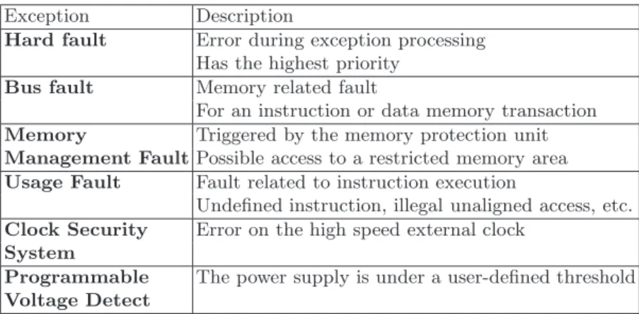
Hardware Faults Interrupts : The microcontroller does not embed any Cyclic Redundancy Check (crc) calculation or advanced mechanism to check code integrity. However, it is able to detect several types of hardware faults. When a specific type of hardware fault is detected, the processor raises its associated interrupt. The standard software library enables the programmer to define the security policy of those interrupts. In the default configuration, the interrupts execute only an infinite loop. The available interrupts are presented in Table 1.
Pulse generator On the fly debug
via USB RS232 Target Motorized stage Coil antenna
Table 1.List of available hardware interrupts Exception Description
Hard fault Error during exception processing Has the highest priority
Bus fault Memory related fault
For an instruction or data memory transaction Memory Triggered by the memory protection unit Management FaultPossible access to a restricted memory area Usage Fault Fault related to instruction execution
Undefined instruction, illegal unaligned access, etc. Clock Security Error on the high speed external clock
System
Programmable The power supply is under a user-defined threshold Voltage Detect
3.3 EMG Impact on the Microcontroller Power Supply
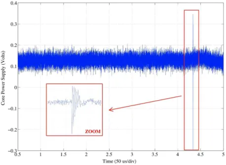
Before the logical effects of an emg can be investigated, the emg profile of the target must be established. Figure 2 shows the target’s power supply during the emg injection. This measurement was done using a differential probe with dc filtering. As we can observe, for a 180V injected emg during 20ns, we obtained a negative spike of less than 50ns width and 300mV amplitude. These voltage variations may seem quite small especially in order to induce faults into the device computations. However, because the power supply measurement was done out of the core, a large part of the perturbation may have been filtered out.
4
Round Modification Analysis on AES: State-of-the-Art
4.1 Advanced Encryption StandardThe Advanced Encryption Standard, according to [12], is a symmetric block cipher that processes data blocks of 128 bits, using cipher keys with lengths of 128, 192, and 256 bits, respectively in 10, 12 or 14 rounds. For the sake of simplicity, we consider in this paper only the 128-bit aes version: denoted aes or aes-128.
aeshas two separated processes: One for the KeyExpansion to derive round keys from the secret key and another one for the DataEncryption. aes-128 performs the encryption process in 10 rounds, after a short initial round. A round key is used during the computations of every round. Hereafter, we use the “K” prefix plus the round number to refer to a round key (e.g. “K9” for the 9th
round key).
To encrypt a plaintext, namely M , the encryption process considers its 16 bytes as a matrix of 4 × 4 bytes. Each round of the algorithm, except the initial and the last ones, includes 4 transformations: First, the value of each matrix
element, i.e. one byte value, is exchanged with the corresponding value in a sub-stitution table (SubBytes or SB). Secondly, a rotational operation on the matrix rows is executed (ShiftRows or SR). In the third step, the algorithm applies a lin-ear transformation to each element and combines it with other values of the same column using a different coefficient of 1, 2 or 3 for each element (MixColumns or MC) in GF(28). The fourth operation is a bitwise xor (AddRoundKey or ARK) is
performed between the value of each element and the corresponding byte of the round key (RoundKey or KRC). Before the first round, an ARK is applied to M
and K (i.e. Round 0). The MC transformation is omitted in the last round. The aes algorithm takes the key K and performs a KeyExpansion routine to generate a key schedule. The KeyExpansion generates a total of Rmax round
keys. KeyScheduling (KS) is a set of linear and non-linear transformations that calculates a new round key from the previous one. The initial round key, K0, is
equal to K. Each of the following round keys (i.e. K1, K1. . . KRmax) is derived
from the previous one.
Algorithm 1 shows an aes DataEncryption implementation which has many similarities with the official aes specifications [12]. In this algorithm 1, C is an intermediate variable used to memorize the aes state throughout the encryption process. The round counter, hereafter RC, is used as an index to select the corre-sponding round key during each ARK transformation. Moreover, RC is compared
to the total round number reference, Rmax, to end the iterative loop preceding
the final round.
Algorithm 1 An aes DataEncryption implementation with on-the-fly keyscheduling.
C ← M KRC←K
C ← C ⊕ KRC
for RC= 1 step 1 to Rmax−1 do
C ← SB(C) C ← SR(C) C ← MC(C) KRC← KS(KRC, RC) C ← C ⊕ KRC end for C ← SB(C) C ← SR(C) KRC← KS(KRC, RC) C ← C ⊕ KRC
According to the algorithm purposes and the circuit resources, various op-tions for KeyExpansion implementation are possible. The KeyExpansion may be executed only one time after a circuit reset or at the beginning of algorithm execution. Thus, the calculated round keys must be stored in the memory for any further encryption. The opposite solution is to calculate the round keys on-the-fly for each encryption. The proposed aes implementation, shown as algorithm 1 calculates each round key on-the-fly at its corresponding round.
A significant part of aes algorithm strength against cryptanalysis is based on its repeated rounds. Any modification in the number of aes rounds may reduce the cipher’s security [10]. This kind of attacks was previously reported in some research experiments. We refer the readers to the next subsection.
4.2 Previous Round Modification Analysis Attacks
In 2005, H. Choukri and M. Tunstall reported in [8] the shortening of the aes execution to only one round (after the initial round) by fault injection and thus finding the key. [10] illustrated that it is also possible to increase or to alter the aesrounds by fault injection and then to discover the key.
Round Modification Analysis principle is based on decreasing or increasing the number of rounds or altering their execution in an algorithm in order to facilitate subsequent cryptanalysis [10]. For instance, let’s consider an attack that makes a jump, after executing a few instructions or the first round at the beginning of algorithm, to its end. The remaining encryption processes are thus skipped. Therefore, the final ciphertext is the product of fewer algorithm
processes that may reveal the key more easily. Besides, an attack that adds or removes only one or two rounds of a normal encryption may permit a differential analysis by using unmodified encryptions as the reference.
Notation:In the following, we use the “R” prefix plus the round number to refer to the transformations involved in an aes round. Hence, R0-R1-R2-R3-R4
-R5-R6-R7-R8-R9-R10, or shortly R0. . . R10, represents the rounds of a complete
(i.e. unmodified) aes. “Mi” represents the aes intermediate state at the end of
round i. We use Rm=j to express that, due to a fault, a round composed of the
ARK ◦ MC ◦ SR ◦ SBtransformations (where “m” stands for middle round) is using
an incorrect round key of index j. Note that j may be higher than the number of rounds. Rf =j has the same meaning for a round without the MC transformation
(“f” stands for final round).
Here, we present briefly the state-of-the-art of previous Round Modification Attacks on aes:
H. Choukri and M. Tunstall’s Attack They showed in [8] that a transient glitch on the power supply of a microcontroller may change the RC value of an iterative cipher. If the opponent changes the RC of an aes program at the beginning of algorithm execution to its final value, the ciphertext will be the product of a single executed round (plus the initial round): R0-Rm or R0-Rf
(according to the notation introduced in section 4.1).
Thus, the cryptanalysis of this very short encryption process does not cor-respond anymore to the complexity of a correct aes execution that includes 10 rounds. [8] introduced a cryptanalysis technique that makes it possible to re-trieve the secret key. This technique obtains eq. 1 by xoring two faulty outputs, Da and Db (Ma and Mb being the corresponding plaintexts):
MC−1(Da⊕Db) = SB(Ma⊕K) ⊕ SB(Mb⊕K) (1)
For every key byte, Eq. 1 yields two different hypotheses. Finally, an exhaus-tive search over the 216
possible keys is made to retrieve the secret key. Note that this cryptanalysis does not require any knowledge of the correct encryptions for Ma and Mb.
J.H. Park et al.’s Attack They reported in [13] a laser fault injection on an atmega128 8-bit microcontroller which embeds an aes. The algorithm imple-mentation is compliant with the algorithm structure proposed in [12].
They described a successful attack that consists in jumping from R1 to R10.
The faulty execution path is R0-R1-R10. Therefore, an additional round is
exe-cuted in comparison to [8] that includes only R0-Rm (or R0-Rf).
The associated cryptanalysis requires data from ten different reduced encryp-tions. Calculations involve four steps of exhaustive search of 240
, 232
, 224
, and 232
K.S. Bae et al.’s Attack They presented in [3] a successful attack by elimi-nating the aes penultimate round. The encryption includes R0. . . R8-R10. This
attack is done by laser fault injection on an atmega128 8-bit microcontroller which embeds an aes. The key is revealed using two pairs of corresponding faulty and correct ciphertexts and then an exhaustive search between the two candidates for each key byte. Therefore, the cryptanalysis needs finding a key between 216 values which has a computational complexity similar to the attack
reported by H. Choukri and M. Tunstall.
J.M. Dutertre et al.’s Attack They showed in [10] three laser fault injection attacks, targeting either the round counter or the total round number reference of an aes. The first attack reduces the aes penultimate round and executes a 9-round aes. The second attack is based on the alteration of the round index during the penultimate and the final rounds. It changes the round key values in AddRoundKeybut does not change the total number of executed rounds. There-fore, the encryption uses corrupted keys at the penultimate and at the final rounds. The key is revealed by using a differential analysis over three pairs of corresponding faulty and correct ciphertexts.
In their third experiment, they reported a Round Addition attack by target-ing the total round number reference. The encryption performs R0. . . R9-Rm=10
-Rf =11. It uses the correct K10for the 10thintermediate round. Nevertheless, the
final AddRoundKey is performed using a block of unknown values as Kf =11. The
attack is exploited by using three pairs of corresponding faulty and correct ci-phertexts through a differential analysis.
These attacks are reported successful on a 8-bit 0.35 µm risc microcontroller. [10] proposed to expand the category of “Round Reduction” in the Fault Attacks into “Round Modification Analysis” which covers a larger domain of algorithm modification attacks, by including the “Round Addition” and the “Round Al-teration”.
4.3 Our Proposed Round Addition Attack
In the third Dutertre et al.’s attack, reported in [10], injecting a fault equal to 0x01 into Rmax, at anytime before the end of R9, lengthens the intermediate
rounds by one round. Therefore a total of 11 rounds is executed. This attack was performed by a surgical laser fault injection to an algorithm almost similar to algorithm 1 (but with pre-calculated round keys). In our research, presented in this paper, we examined the feasibility of a similar Round Addition attack on the aes by an em glitch.
To meet this requirement, a solution may be an emg attack on the RC incrementation instruction at the end of R9. Therefore, the RC incrementation
instruction may be skipped, due to the emg effect on the mcu. Thus, RC value remains 9 and another intermediate round, denoted R′
In an aes implementation, similar to the Algorithm 1, each round key is calculated on-the-fly at its corresponding round. The KeyScheduling process is a function of the previous round key and the current index of the RC. Therefore, for the redundant R′
m=9, a new round key (i.e. K9′) is derived from the previous
one, i.e. K9. In the same way, another invalid key value is derived from K9′ for
the Rf =10, denoted as K10′ .
Finally, the encryption sequence may be: R0-R1. . . R9-R′9-R′10, including a
total of 11 executed rounds. In this case, the success of the attack requires a differential cryptanalysis distinct from the technique reported in [10].
In the aes algorithm, each middle round is composed of the ARK ◦ MC ◦ SR ◦ SB transformations. The final round does not include the MixColumns transforma-tion. For the ease of writing the equations, we denote the final round transfor-mations before the ARK by the FinalRound or the FR operation, described in Eq. 2:
FR[Mi+1] = SR ◦ SB[Mi] (2)
We also denote the middle round transformations before the ARK by the MiddleRound or the MR operation, described in eq. 3:
MR[Mi+1] = MC ◦ SR ◦ SB[Mi] (3)
The cryptanalysis of our proposed attack scheme requires only two pairs of correct and faulty ciphertexts (Ca,Da), (Cb,Db). Considering two pairs of
cor-responding faulty and correct encryptions, we have:
Ca = FR[M9a] ⊕ K10 (4) Cb = FR[Mb 9] ⊕ K10 (5) Da= FR[MR[Ma 9] ⊕ K9′] ⊕ K10′ (6) Db= FR[MR[M9b] ⊕ K9′] ⊕ K10′ (7)
By combining Eq. 4 and 5, and with an extra MC operation, we get :
MR[Ma 9] ⊕ MR[M b 9] = MC[C a⊕ Cb] (8)
In a similar way, by combining Eq. 6 and 7, we get Eq. 9 where K′
9is removed: FR−1[Da ⊕K′ 10] ⊕ FR−1[D b ⊕K′ 10] = MR[M a 9] ⊕ MR[M b 9] (9)
Then by combining Eq. 8 and 9 we obtain :
FR−1[Da ⊕K′ 10] ⊕ FR−1[D b ⊕K′ 10] = MC[C a ⊕Cb] (10)
Since Ca, Cb, Da and Db are known values, Eq. 10 can be resolved by
per-forming an exhaustive search over each of K′
10byte. This exhaustive search leads
to 2 hypotheses for each of K′
10 bytes. K10′ and K9′ are calculated using a
cor-rect, but redundant sequence of KeyScheduling. So, a second exhaustive search among 216 whole-key hypotheses is necessary in order to obtain a unique value
for each byte of K′
10. Therefore, K9′ and consequently K are recovered by simply
putting K′
10 through the inverse of KeyScheduling.
5
Experimental Results
In this section we describe a practical emg injection into the instruction corre-sponding to the aes round counter incrementation. It results in the execution of a second 9th round denoted R′
9(as described in the previous section).
5.1 Experimental Outline
A software version of the aes algorithm has been implemented on the microcon-troller. This version provides aes subroutines with an “on-the-fly” KeyScheduling. The encryption process is written in C code. Its structure is given in Algorithm 1. We compile this source code using Keil mdk-arm toolchain.
To monitor our microcontroller and our injection bench, we used a com-puter application. This application communicates with our microcontroller by using a Serial Wire Debug (swd) interface. This interface is a non-intrusive 2-pin alternative jtag debug interface [1]. The experimental process used for our experiments is described in algorithm 2.
The position of the probe on the top of the circuit’s surface, influences the fault occurrence rate. We define the probe position by using a simple trial and error empirical method.
Algorithm 2Experimental process
Set the relative position of the antenna on top of the surface of the package Define a time interval [tmin;tmax] to inject the emg
Initialize the pulse generator Define a time step ∆t
Initialize a random fixed key and plaintext for t= tminstep ∆t to tmaxdo
microcontroller reset() launch AES()
send pulse with delay(t) sleep(100ms)
microcontroller stop()
results= microcontroller get status() print and store(results)
The microcontroller get status() function at the end of the aes com-putation displays the registers’ values, the 16-byte ciphertext’s value and the interrupt status flags.
For our experiments, we used a 100ps ∆t resolution. The sleep (100ms) en-ables us to be sure that the encryption will be finished when the microcontroller is stopped. After 100ms, we know that the microcontroller is in one of the fol-lowing states :
– Running the infinite loop at the end of the aes computation – Running the infinite loop of an interrupt (as detailed in section 3.2) – Crashed
5.2 Results
Our aim was to disrupt the instruction that increments the round counter. Thus, we targeted a 500ns time interval between the 9thand the 10throunds of the aes
computation. For each encryption, we changed the pulse injection time. During the experiment, the emg injection time spanned the entire time interval, from the beginning to the end, by steps of 100ps.
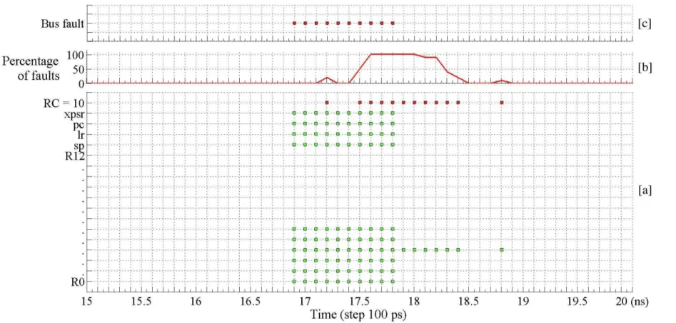
For each of these time steps, 100 encryptions of the same key and plaintext were carried out. The different types of emg impacts in this experiment are reported in Fig. 3. Due to the large number of samples we got, we decided to plot a 5ns interval. We chose a time interval during which the aes round counter was faulted.
At the beginning of the experimental process, we performed a first calibration step. This first execution enabled us to get the normal internal register and output values without any emg injection. In Fig. 3-a, we got a fault when the output value was different from the one from our calibration execution. The y-axis of Fig. 3-a represents the values of internal registers (r0-r12, sp, lr, pc, xpsr) and the final value of the round counter (rc=10). On this figure, green squares represent faults on the internal registers while red squares represent faults on the round counter.
Some of the faulted values mentioned on the graph are actually artifacts of our experiments, due to our experimental process. In the case that an interrupt subroutine is called, many registers are changed in the new stack frame. Thus, their values are different from the calibration execution. However, this is not directly due to emg injection and cannot really be considered as a fault.
According to this timing cartography, our fault injection technique based on emginjection close to a circuit enables to easily target the aes round counter in-crementation instruction. More precisely we observed that the aes round counter has been faulted for different injection times, but in a very small time interval [17.2ns -18.8ns]. We also observed that, in the event that no interrupt is raised, the internal cpu register r3 was the only corrupted value.
Figure 3-b reports the fault occurrence rate as a function of time. As we can observe, a curve that seems to look like a gaussian curve is obtained. This curve is
centered around the interval in which the aes round counter was corrupted. The gaussian peak’s center corresponds to the interval’s center. For a time interval, the fault occurrence rate is equal to 100%.
Figure 3-c reports the timing interval where the microcontroller was able to detect the emg and then raises its associated interrupt. In our case, the “Bus fault” exception was the only one triggered during our experiment. This ex-ception indicates that a fault for an instruction or data memory transaction is detected. As we can observe, the interrupts were localized in [16.9ns -17.8ns]. Considering the time interval [17.9ns -18.8ns], we were able to perform the pro-posed attack without being detected by the microcontroller.
As we lack information about the microcontroller’s design, it is very tough for us to precisely know the impact of the emg inside the microcontroller. However, at a macroscopic level, we are able to sort the impacts into :
– Nothing happens
– A fault is produced and an interrupt is raised: [16.9ns -17.8ns]
– A fault is produced, no interrupt is raised, an assembly instruction is skipped: [17.9ns -18.8ns]
6
Conclusion
In this paper we presented a new Round Addition attack on a software imple-mentation of the Advanced Encryption Standard (aes) algorithm. The proposed attack consists in targeting the round counter RC in order to induce the exe-cution of a second penultimate round. The fault is induced at the end of the penultimate round during the incrementation of RC. emg injection enables us to get effects that are equivalent, at a macroscopic level, to an instruction skip with a high occurrence rate and without triggering hardware interrupts. The proposed attack is achieved by skipping the counter increment instruction. As a result the faulty aes executes 11 rounds and enables us to recover the encryption key with only two pairs of corresponding correct and faulty ciphertexts.
Future works: According to our experimental results and at a macroscopic level, this instruction skip fault model was used to describe an attack model. However, the faults induced by emg injection are probably more complex than an instruc-tion skip and our fault model can be completed by using future experimental results. For further studies, we will also try to improve the way we choose our probe position.
Acknowledgment
References
1. ARM. arm debug interface v5.
2. ARM. Documentation about cortex-m3 processors.
3. K.S. Bae, S.J. Moon, D.H. Choi, Y.J. Choi, D. Choi, and J.C. Ha. Differential fault analysis on aes by round reduction. In Proceedings of ICCIT’2011, pages 607–612. ieee, 2011.
4. Josep Balasch, Benedikt Gierlichs, and Ingrid Verbauwhede. An in-depth and black-box characterization of the effects of clock glitches on 8-bit mcus. In Pro-ceedings of FDTC’2011, pages 105 –114, 2011.
5. A. Barenghi, L. Breveglieri, I. Koren, and D. Naccache. Fault injection attacks on cryptographic devices: Theory, practice, and countermeasures. Proceedings of the IEEE, 2012.
6. Eli Biham and Adi Shamir. Differential fault analysis of secret key cryptosystems. In Proceedings of CRYPTO’1997, volume 1294 of lncs, pages 513–525. Springer-Verlag, 1997.
7. Dan Boneh, Richard DeMillo, and Richard Lipton. On the importance of checking cryptographic protocols for faults. In Proceedings of EuroCrypt 1997, volume 1233 of lncs, pages 37–51. Springer-Verlag, 1997.
8. Hamid Choukri and Michael Tunstall. Round reduction using faults. Proceedings of FDTC’2005, pages 13–24, 2005.
9. A. Dehbaoui, J.M. Dutertre, B. Robisson, and A. Tria. Electromagnetic transient faults injection on a hardware and a software implementations of aes. In Proceed-ings of FDTC’2012, pages 7–15. IEEE, 2012.
10. J.-M. Dutertre, A.-P. Mirbaha, D. Naccache, A.-L. Ribotta, A. Tria, and T. Vaschalde. Fault round modification analysis of the advanced encryption stan-dard. In Proceedings of HOST’2012. IEEE, 2012.
11. Chong Kim and Jean-Jacques Quisquater. Fault attacks for crt based rsa: New attacks, new results, and new countermeasures. In Proceedings of WISTP’2007, volume 4462 of LNCS, pages 215–228. Springer Berlin / Heidelberg, 2007. 12. NIST. Announcing the Advanced Encryption Standard (aes). Federal Information
Processing Standards Publication, n. 197, November 26, 2001.
13. JeaHoon Park, SangJae Moon, DooHo Choi, YouSung Kung, and JaeCheol Ha. Differential fault analysis for round-reduced aes by fault injection. etri Journal, 33(3):434–442, 2011.
14. F. Poucheret, K. Tobich, M. Lisart, B. Robisson, L. Chusseau, and P. Maurine. Local and direct em injection of power into cmos integrated circuits. In Proceedings of FDTC’2011. IEEE, 2011.
15. Jean-Jacques Quisquater and David Samyde. Eddy current for Magnetic Analysis with Active Sensor. In Proceedings of Esmart’2002, 2002.
16. J-M Schmidt and C Herbst. A practical fault attack on square and multiply. In Proceedings of FDTC’2008, pages 53–58, 2008.
17. J¨orn-Marc Schmidt and Michael Hutter. Optical and em fault-attacks on crt-based rsa: Concrete results. In Proceedings of Austrochip’2007, pages 61–67. Verlag der Technischen Universit¨at, 2007.