HAL Id: cea-02928262
https://hal-cea.archives-ouvertes.fr/cea-02928262
Submitted on 2 Sep 2020
HAL is a multi-disciplinary open access
archive for the deposit and dissemination of
sci-entific research documents, whether they are
pub-lished or not. The documents may come from
teaching and research institutions in France or
abroad, or from public or private research centers.
L’archive ouverte pluridisciplinaire HAL, est
destinée au dépôt et à la diffusion de documents
scientifiques de niveau recherche, publiés ou non,
émanant des établissements d’enseignement et de
recherche français ou étrangers, des laboratoires
publics ou privés.
Christophe Venard, Thierry Beck, Bruno Bernardin, Alain Conti, David
Gentet, Pierre Lamagnere, Pierre Sciora, Denis Lorenzo, Annick Tosello, Marc
Vanier, et al.
To cite this version:
Christophe Venard, Thierry Beck, Bruno Bernardin, Alain Conti, David Gentet, et al.. The ASTRID
core at the midterm of the conceptual design phase (AVP2). ICAPP 2015 - International Congress
on Advances in Nuclear Power Plants, May 2015, Nice, France. �cea-02928262�
The ASTRID core at the midterm of the conceptual design phase (AVP2)
Christophe VENARD, Thierry BECK, Bruno BERNARDIN, Alain CONTI, David GENTET, Pierre LAMAGNERE, Pierre SCIORA, Denis LORENZO, Annick TOSELLO, Marc VANIER
Alternative Energies And Atomic Energy Commission CEA, 13108 Saint Paul lez Durance, France
Tel: (33) 4 42 25 45 63 , Fax: (33) 4 42 25 70 09, Email: Christophe.venard@cea.fr Anne-Claire SCHOLER, Denis VERRIER
AREVA-NP, 10 rue Juliette Récamier, 69456 Lyon Cedex 06, France Florent BARJOT, Damien SCHMITT
EDF R&D, 1 avenue du Général de Gaulle, 92141 Clamart, France
Abstract – Within the framework of the French ASTRID project, core design studies are being
conducted by the CEA with support from AREVA and EDF. The design studies include the GEN IV reactor objectives, particularly in terms of improving safety.
Options selection was performed at the conclusion of the pre-conceptual design phase. The CFV core was confirmed as the reference core for the ASTRID project. The design route of the core has been reoriented for the conceptual design phase of the ASTRID project (Limitation of the core diameter, innovative options of control and shutdown architecture, introduction of complementary safety devices for prevention and mitigation of severe accidents, choice of S/A internal storage instead of external storage, neutron shielding on the inner vessel components).
A new version of the CFV core (CFV V3) which integrates these above options was proposed at the end of 2013. This paper describes the main characteristics and performances of the CFV V3 core. It particularly focuses on the design studies of internal storage.
I. INTRODUCTION
The pre-conceptual design phase (AVP1) for the ASTRID1, 2 prototype (Advance Sodium Technological Reactor for Industrial Demonstration) ended in 2012. Two kind of cores have been studied :
the SFR V2b concept3 at 1500 MW, an homogenous
core with a low reactivity swing.
the CFV concept4, an heterogeneous core based on the introduction of a sodium plenum zone, an absorbing zone in upper neutron shielding and an internal fertile in a specific core geometry that leads to a low total sodium void effect.
The CFV is the reference during this design phase. Two versions of the CFV core were studied. The version V15 showed a promising safety improvement compared to SFR V2b. The options chosen (decrease of nominal fuel temperature, linear power rate and reactivity swing) for the
CFV V26 further improves the natural behavior during unprotected transients.
Option selection and cost savings processes were performed at the conclusion of the pre-conceptual design phase. They confirmed the choice of the CFV core as the reference core for the ASTRID project. The design routes of the core have been reoriented for the conceptual design phase of the ASTRID project :
limitation of the core diameter less than 3,4 m,
innovative options of control and shutdown architecture : control and safety absorber rods used to manage the core reactivity during the cycle,
introduction of complementary safety devices for severe accidents prevention and mitigation,
choice of S/A internal storage (inside the reactor vessel) instead of external storage,
A new version of the CFV core (CFV V3) which integrated these above options was proposed at the end of 2013. This paper describes the CFV V3 and focuses on the design studies of internal storage.
II. SAFETY GOALS AND PERFORMANCE TARGETS
The safety and performance goals assigned to the CFV core by the ASTRID project can be synthesized by :
a natural behavior as favorable as possible which could be supplemented by some Safety Complementary Devices (DSC-P) during Unprotected Loss Of Flow (ULOF) transients to avoid sodium boiling with sufficient margins or an unprotected Control Rod Withdrawal (CRW) with a criterion of "0% molten fuel",
a negative sodium void effect,
and a search for the best performance in terms of fuel burn-up and S/A residence time and breeding gain. These objectives translate into decoupling safety criteria or safety goals for the core design, the most structuring ones being listed below :
during the ULOF
- the sodium temperature must be lower than the saturation temperature of sodium,
- the temperature of the fuel S/A clad and the wrapper tube have to be respectively lower than 825 °C and 800 °C,
- the asymptotic coolant temperature has to be lower than 700 °C.
respect of the reactivity control requirements,
maximal nominal temperature of the fuel S/A clad (NCT) lower than 620 °C in the core,
clad damage lower than 110 dpa NRT(Fe)
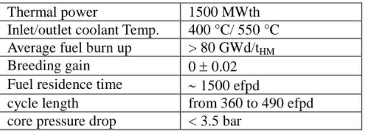
The main performance targets are given in TABLE I.
TABLE I
Performances targets of the CFV core
Thermal power 1500 MWth Inlet/outlet coolant Temp. 400 °C/ 550 °C Average fuel burn up > 80 GWd/tHM
Breeding gain 0 0.02 Fuel residence time 1500 efpd
cycle length from 360 to 490 efpd core pressure drop < 3.5 bar
III. LAYOUT OF THE CFV CORE (CFV V3) III.A Architecture of Absorbers S/As and Shutdown
system
The absorber device of the CFV core is composed of 3 kinds of S/A : control and shutdown S/As (RBC), diverse control and shutdown S/As (RBD) and safety complementary S/As (DCS-P). All RBC and RBD devices are involved in the control and the shutdown of the reactor. RBD S/As can be inserted even in a deformed core.
The number and the layout of the absorber S/As is optimized to minimize their numbers. This optimization takes into account :
the variability of the fuel isotopic vector
reactivity provisions for the needs of experimental and industrial demonstration programs
the dimensional constraints of the different systems that cross the above core structure,
the reactivity control requirements,
the management of the core power distributions,
non fuel melting during a CRW,
and a residence time equal to those of the fuel S/As. This optimization has led to an absorber system with 9 RBC, 9 RBD and 3 DCS-P (see .Fig. 1).
Inner core Outer core Dummy S/A RBC RBD DCS-P
Fig. 1 Layout of the absorber system
III.B Neutron Shielding of the Core
The core neutron shielding is designed to limit the irradiation damage on the internal components of the vessel and the sodium activation of the secondary heat transfer circuit. The sodium activity in the steam generator area must be lower than 20 Bq/cm3. The upper neutron shielding is integrated into fuel S/A. It also contributes to the sodium void effect of the CFV core4.
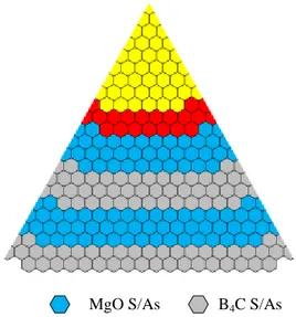
The design of the core neutron shielding is optimized in respect with the ratio efficiency/cost on the basis of selected material. The shielding materials were chosen according to feasibility criteria and experience feedback. The upper neutron shielding is provided by a boron carbide sleeve. The boron is 90% enriched in 10B in the lower part. The radial neutron protection of the core consists of 11 rows of S/As (sandwich of MgO reflector S/As and natural boron carbide shielding S/As (see Fig. 2)). The secondary sodium activity is about 8 Bq/cm3 including the borated steel shielding of the intermediate heat exchanger. The design studies of the core shielding are presented in reference 7.
MgO S/As B4C S/As
Fig. 2 Radial neutron shielding of the CFV core
III.C Design of the Internal Storage and Debugging Positions
The purpose is to find out the capacity, the implementation and the cooling flow rate of the internal storage. This requires considering the core management during the whole life of the reactor and studying the impact of the internal storage on the core with respect to neutron shielding, criticality, thermohydraulic and mechanical behavior.
III.C.1 Internal storage capacity and number of debugging positions
The assessment of the internal storage capacity needs to plan the core management during the all life of the reactor taking into account :
the phase from start-up core to equilibrium core,
the phase of increase in S/As performances (from 60 dpa to 150 dpa or residence time from 720 efpd to 2000 efpd),
the different transitions phases in core management. Core management is optimized in order to minimize the under-burnup of the fuel S/As and/or the internal storage capacity.
The core management studies are carried out on a core managed with 4 batches of 72 S/As and an irradiation cycle of 360 efpd. The S/As can be unloaded when their decay power is lower than 3 kW or 1 kW if a clad failure has been detected. The load factor of the reactor is 0.7 during the transition phase from start-up core to equilibrium core and then it is 0.9. From these data, fuel S/As must remain during 1 core irradiation cycle (360 efpd) in internal storage or for 3 to 4 cycles in debugging positions (with a clad failure) before being unloaded.
Among all studied scenarii of core management, the most interesting one considers an internal storage capacity of 3 batches (216 positions) during the phase from start-up core to equilibrium core and 2 batches (144 positions) during the core equilibrium phase. Morever 28 debugging positions are required with a hypothesis of 7 clad failures per cycle.
III.C.2 Implementation and Management of the Internal Storage and debugging positions
There should not be any significant neutron coupling between the internal storage and the core. The fission power of the fuel S/A in internal storage position must be much smaller than its decay power.
The internal storage must then be implemented behind the fifth row of the lateral shielding. The neutron flux is there at least 104 times lower than in the last row of the core (see Fig. 3).
The internal storage should not lead to significant degradation of the neutron core shielding or of the mechanical behavior of the core. Moreover it should remain subcritical, with margin, because no reactivity control devices are provided unlike in the core.
III.C.2.a Internal storage impact on the sodium activation Three representative configurations of internal storage have been considered (see Fig. 4) :
Internal storage and debugging positions in periphery of core lateral shielding (configuration C11_C12) o 150 outer core fuel S/As in row 11 and 12, o plus 60 B4C S/As in row 12.
Internal storage and debugging positions in the middle of the lateral shielding, behind the fifth row (configuration C6_C8)
o 150 outer core fuel S/As in row 6 and 8, o plus 60 B4C S/As in row 12.
Internal storage and debugging positions are empty o 150 empty positions in row 6 and 8.
Fig. 4 : Internal storage configurations for sodium activation studies
The secondary sodium activity values are given in the TABLE II. 150 fuel S/As in internal storage or empty positions leads to a low impact on the secondary sodium activity.
TABLE II
Internal storage impact on the secondary sodium activation
Configuration Activation (Bq/cm3) Reference (§III.B) 7.7
C11-C12 7.0 C6_C8 9.1 Empty C6_C8 8.5
The studies are presented in reference 7. III.C.2.b Internal storage criticality
The objective of this preliminary safety-criticality study of the internal storage is to assess the possible requirements on the internal storage layout. The internal storage k-effective has to be lower than 0.95 in normal situations.
The calculations are performed for the reactor at the cold shutdown state (180 °C). The plutonium content of the fissile material is 32 % (oxide volume) associated to the Pu isotopic composition (71% 239Pu, 17% 240Pu, 11% 241Pu and 1% 242Pu) usually used in the safety-criticality studies in France. Fuels S/As in internal storage are fresh. Neutron coupling between the internal storage and the core is neglected because they are separated by at least 3 MgO S/As and 2 B4C S/As rows. The internal storage is modeled
by a one dimensional plane geometry (see Fig. 5). Computations are carried out with ERANOS9 and validated by comparison with MCNP
Fig. 5 Internal storage modeling for safety-criticality studies
The maximum number of fuel S/As contiguous rows in the internal storage is assessed by varying the sodium density in the internal storage and the neutron shielding. Taking into account the axial neutron leakage, k-effective of internal storage decreases to 7000 pcm in the case of the two rows in IS configuration. TABLE III shows that
100% Na density is the optimum moderation,
The fuel S/As rows should be separated by at least one row of shielding S/As.
TABLE III
Internal storage k-effective according the number of fuel S/As rows and the sodium density – one dimension modeling
Fuels S/As contiguous rows in IS Na relative density 1 2 3 100% (IS), 100% (MgO & B4C) 0.7744 1.1865 1.4303 63,2% (SI), 100% (MgO & B4C) 0.7733 - - 31,6% (IS), 100% (MgO & B4C) 0.7725 - - 0% (IS), 100% (MgO & B4C) 0,7718 1.1800 1.4286 0% (IS), 0% ((MgO & B4C) 0,7632 1,1724 1,4233 Two alternative configurations of internal storage are studied with two fuel S/As rows separated by a B4C S/As
row in both of them. In the first configuration (Config.1), the internal storage is surrounded by a B4C S/As row on
one side and by a MgO S/As row on the other side ; a B4C
S/As row is on the both sides in the second configuration (Config. 2). Calculations performed on the one dimensional plane geometry show that the two internal storage configurations are acceptable, given the important conservatism of the geometry modeling (TABLE IV).
TABLE IV
k-effective of internal storage separated by a B4C S/As row
Config. 1 Config. 2
k
eff 0.9588 0.8412To comply the k-effective criterion without any requirement, fuel enrichment should not exceed 25% or 22.4% in reactivity equivalent 239Pu. Maximum Pu content to be encountered during the ASTRID life is lower than 18% in reactivity equivalent 239Pu. From the safety-criticality point of view, two contiguous rows of fuel S/As are acceptable in the internal storage.
The results of these preliminary studies show that there is no particular requirement on the configuration of the internal storage from the point of view of the safety-criticality.
III.C.2.c Core mechanical behavior
The analysis of static mechanical equilibrium of the CFV core shows that the fuel S/As in the internal storage contribute to the natural restraint of the core. Operating parameters (maximum bowings, maximum handling force,
and so on) are not much modified by the internal storage. The compliance with the functional constraints and mechanical requirements are demonstrated.
From the point of view of the dynamic behavior, the internal storage introduces some discontinuities in the peripheral S/As rows. Following the internal storage management some positions can be occupied by fuel S/As or empty. To identify possible difficulties on the mechanical behavior, several cases of calculation were considered for two types of mechanical loading (seismic and pulse loadings).
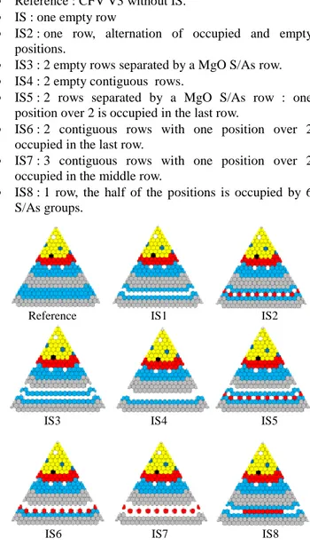
In the case of the design earthquake (with seismic isolation of reactor building), 9 configurations were studied (Fig. 6) :
Reference : CFV V3 without IS.
IS : one empty row
IS2 : one row, alternation of occupied and empty positions.
IS3 : 2 empty rows separated by a MgO S/As row.
IS4 : 2 empty contiguous rows.
IS5 : 2 rows separated by a MgO S/As row : one position over 2 is occupied in the last row.
IS6 : 2 contiguous rows with one position over 2 occupied in the last row.
IS7 : 3 contiguous rows with one position over 2 occupied in the middle row.
IS8 : 1 row, the half of the positions is occupied by 6 S/As groups.
Fig. 6 Core mechanical behavior under seismic loading - Studied configurations
Reference IS1 IS2
IS3 IS4 IS5
Internal storage and empty positions have little effect on the maximum characteristics values of the core behavior and on the mechanical loadings on the S/As. The IS8 configuration (S/As groups in IS) is the most unfavorable towards contact forces to pads (40% higher than the reference case CFV V3) still without questioning mechanical design of S/As.
In case of a pulse loading 3 configurations are studied : CFV V3, IS1, and IS2. They were subjected to a pulse type loading which source is located in the midplane in the core center. The energy pulse creates a core radial expansion followed by a compaction centered on the central axis of the core. The studies show that the internal storage has no major influence on the core compaction worth (Fig. 7).
Fig. 7 Core maximum compaction vs pulse energy
The internal storage has a limited impact on the static and dynamic mechanical behavior of the core and on the mechanical loadings sustained by the S/As.
III.C.2.d Thermohydraulic of internal storage and debugging positions
To respect the temperature limit conditions in fuel pins, the cooling flow rate of the internal storage and debugging positions should ensure the sufficient cooling in all considered situations (category 1 and category 2 situations). This study was carried out with the TRIO_U MC2 code.
The fuel maximal clad temperature (MCT) limits are :
550 °C in category 1,
550°C and 600°C during 2 hours at maximum in category 2
MCT takes into account the uncertainties on the inlet core temperature (nominal and evolution during the transient), S/A power, cooling flow rate and bundle geometry.
The dimensioning load case is the LOSSP (Loss of Station Supply Power) incident with the failure of one diesel i.e. with a complete loss of one primary pump. The core flow decreases until 14% of nominal value. During this transient with a failure of one decay heat removal device, the core inlet temperature rises to 489 °C after 26 minutes and decreases to 463 °C after 2 hours.
The fuel S/As power in internal storage is the sum of the decay power and neutron power (fission and gamma capture). The neutron power of one fuel S/A in internal storage (6th row of the lateral neutron shielding) is about 600 W.
We consider a decay time of 3 days for the handling situations, 4 days for fuel S/As loaded in debugging positions and 15 days for fuel S/As loaded in internal storage positions.
A design margin of 20% on the S/A total power value is taken :
PS/A (3 d.) = 30.6 kW
PS/A (4 d.) = 27.5 kW
PS/A (15 d.) = 16.1 kW
To assess the cooling flow rates of the internal storage and debugging positions we associate the maximal core inlet temperature (489 °C) during the design transient to the MCT limit for the category 2 (600 °C). The fuel Maximum Clad Temperature (MCT) should not exceed 550 °C for more than 2 hours. The maximal inlet temperature is about 463 °C outside of this time interval. This temperature is associated to the MCT limit 550 °C. TABLE V shows the required flow to fulfill the MCT criteria.
TABLE V
S/As cooling flow rate in internal storage and debugging positions during the incidental transient
Debugging positions Internal storage PS/A (kW) 27.5 16.1 Tinlet (°C) 463 489 463 489 QS/A min (kg/s) during LOSSP 0.341 0.27 0.208 0.162 Toutlet (°C) 529 574 529 574 NCT(*) (°C) 530 575 530 575 MCT (°C) 550 600 550 600
(*) NCT : maximal Nominal Clad Temperature
The nominal flow rates corresponding to the values given in TABLE V are 1.5 kg/s for the internal storage position and 2.5 kg/s for the debugging position.
The total cooling flow rate through the internal storage and debugging positions is :
Reference IS1 IS2 Pulse energy (kJ) A v er a g e r a d iu s co mpa ct io n ( m )
286 kg/s (3.6% of the core total flow rate) for an internal storage capacity of 144 S/As (2 batches),
394 kg/s (5% of the core total flow rate) for an internal storage capacity of 216 S/As (3 batches),
The average temperature of the hot collector is fixed at 550 °C. The internal storage impact on the core outlet temperature is +6°C in the first case and +8°C in the second case.
III.C.2.e Conclusion
The core management studies defined the internal storage and debugging capacity. Their implementation arose from safety-criticality and neutron shielding studies. The core mechanical studies have identified the constraints on the internal storage and debugging management.
The nominal capacity of the internal storage is 144 positions (2 batches). To retain some flexibility in the core management (like in the start-up to equilibrium phase), it is expected 72 additional positions (1 batch) in the lateral neutron shielding which can be occupied by fuel S/As. There are 28 debugging positions.
The internal storage and the debugging positions are located rather in the periphery of the core lateral neutron shielding. The core management does not require these positions to be always occupied. On the other side, to minimize thermal loading on the above core structures, the core bypass flow should be as small as possible. Then, it would be preferable if the empty positions of the internal storage and debugging to be occupied by non or low flowing S/As like B4C S/As.
III.D Core Layout
The configuration of the core CFV V3 incorporates the conclusions and recommendations of the various reviews that occurred at the end of the pre-conceptual design phase (AVP1) :
Innovative architecture of the control and shutdown rods called architecture “RID”. This architecture is composed of 2 kinds of absorbers, RBC (control and shutdown device) and RBD (diverse control and shutdown device). They both manage the core reactivity during the cycle. But RBD S/As can also be inserted in a deformed core. Compared to previous architectures (EFR or SPX), this solution saves three absorbers S/As for the same efficiency.
Complementary safety device for prevention (DCS-P) and mitigation (DCS-M) of severe accidents have been implemented in the core : 3 hydraulic trigger absorber DCS-P on flow decrease (DCS-P-H) and 21 crossing pipes DCS-M (DCS-M-TT).
Lateral neutron shielding provided by 11 S/As rows with an alternation of MgO S/As and B4C S/As.
B4C upper neutron shielding whose lower part is
enriched to 90% in 10B to provide a negative sodium void effect.
Introduction of an internal storage.
Natural behavior improvement of the CFV V2 during ULOF was not significant enough to offset the radial size increase (1 more fuel S/As row than CFV V1). It was therefore decided to go back to the CFV V1 contour.
The main characteristics of the core are gathered in the TABLE VI and compared with the former version of the core CFV V2.
TABLE VI
Main characteristics of the CFV core
CFV V2 CFV V3 nb of fuel S/As 355 288 nb of pins per S/As 271 217 fuel pin diameter (mm) 8.57 9.7 S/A pitch (cm) 17.5 17.17 inner/outer fissile height (cm) 60/90 60/90 inner/lower fertile height (cm) 20/30 20/30 inner/outer Na plenum (cm) 40/30 40/30
The central position occupied by a dummy S/A in the nominal configuration, will be able to accommodate an absorber S/A (RBC or RBD). During reactor life the core outer contour will be able to evolve : 12 peripheral positions of the core in reflector zone will be able to be loaded with fuel S/As.
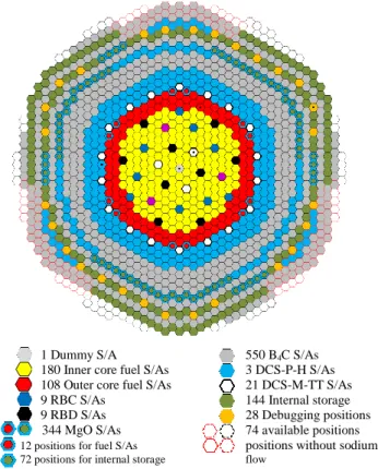
During reactor life the capacity needs of the internal storage range from 0 to 216 positions (3 batches of fuel S/As). 72 positions are necessary for the core during equilibrium cycles. Free positions on the diagrid can be used as "buffers". They can be occupied by reflectors S/As in the internal storage configuration wiyh 216 positions. The CFV V3 core layout is shown in Fig. 8.
1 Dummy S/A 550 B4C S/As 180 Inner core fuel S/As 3 DCS-P-H S/As 108 Outer core fuel S/As 21 DCS-M-TT S/As 9 RBC S/As 144 Internal storage 9 RBD S/As 28 Debugging positions 344 MgO S/As 74 available positions 12 positions for fuel S/As positions without sodium 72 positions for internal storage flow
Fig. 8 CFV V3 core layout
IV. PERFORMANCES IV.A Neutron Performances
Neutronic core calculations were performed with the CEA's reference code system ERANOS8,9.
The core is managed with 4 batches of fuel S/As. The fuel residence time is 1440 efpd and the equilibrium cycle length is 360 efpd. The main neutron performances are presented in TABLE VII.
TABLE VII CFV V3 neutron performances
PuO2 enrichment (vol. %) Inner core
Outer core 22.95 19.95
Pu mass (t) 4.8
Reactivity loss per day (pcm/efpd) 3.8 Average breeding gain -0.01 Average power density (W/cm3) 231 Maximum S/As power (MW) 6.1 Maximum linear rating (W/cm) 465 Average burn-up (GWd/tHM) 81
βeff (pcm) 368
EOEC sodium void worth ($) -0.5
The CFV V3 complies with the performance requirements of the ASTRID specifications in terms of fuel residence time, fuel cycle length, average burn-up and breeding gain.
IV.B Core Hydraulic Characteristics and Mass Flow rates
The CFV V3 core hydraulic studies were carried out with the CEA's code TRIO_U-MC2. The maximal nominal clad temperature (NCT) should be lower than 620 °C and the S/As outlet temperature discrepancies between 2 neighboring S/As is limited to 50 °C. The core hydraulic optimization leads to a distribution over 5 cooling groups for the fuel S/As (TABLE VIII) to get a flat temperature distribution.
The core pressure drop is about 3 bar. The maximal NCT and outlet temperature of fuel S/As are respectively 618 °C and 574 °C. The impact of the internal storage and the debugging zone is about +6 °C on the fissile outlet temperature.
TABLE VIII
Mass flow rates of S/As
S/As number Flow per S/A (kg/s) Flow per group (kg/s) fuel S/As 288 7208 group 1 (inner core) 120 26.1 3132 group 2 (inner core) 60 23.6 1416 Inner core 180 4548 group 3 (outer core) 24 26.7 641 group 4 (outer core) 51 25.0 1275 group 5 (outer core) 33 22.5 743
Outer core 108 2660
IV.C Control Rod Withdrawal
In the "RID" architecture, all the absorber S/As (RBC and RBD) are used to manage the core reactivity unlike in EFR or SPX architecture where only RBC S/As were used. Therefore, the absorbers rods are less inserted into the core by about 5 cm.
In case of control rod withdrawal (CRW), the reactivity insertion and local over power are lower, like shown in TABLE IX.
TABLE IX
CRW with "RID" and "EFR-like" absorber architecture
Architecture inserted reactivity (pcm) ΔPlin/Plin % "RID" 98 13.6 "EFR-like" 142 22.2 The core behavior during CRW will be improved.
V. CONCLUSIONS
The CFV V3 design integrates the options selection performed at the end of the pre-conceptual design phase : control and shutdown "RID" architecture, introduction of complementary safety devices for prevention and mitigation of severe accidents, choice of a S/As internal storage. The neutron performances of the CFV V3 core comply the ASTRID project requirements.
The new absorber rods architecture leads to a better behavior during CRW transient.
The main internal storage impact on the core physical characteristics is an increase of 6 to 8 °C of the sodium outlet temperature of the fuel S/As.
ACKNOWLEDGMENTS
The authors wish to thank all the teams involved in the core design at CEA, AREVA and EDF.
NOMENCLATURE
BEOC : Beginning Of Equilibrium Cycle
CFV : "Coeur à Faible Vidange" Low Sodium void Core CRW : Control Rod Withdrawal
DCS :Safety complementary device
DCS-P : Prevention Safety complementary device DCS-P-H : hydraulic trigger DCS on flow decrease DCS-M : Mitigation Safety complementary device DCS-M)-TT : Crossing pipe DCS-M
EFPD : Equivalent Full Power Day EOEC : End Of Equilibrium Cycle IS : Internal Storage
MCT : Maximal clad temperature NCT : Nominal clad temperature Plin : Linear power rating
RBC : Control and shutdown device RBD : Diverse control and shutdown device S/A : Subassembly
REFERENCES
1. P. LE COZ, et al., “Sodium-Cooled Fast Reactors: the ASTRID Plant Project” – Proceedings of ICAPP 2011, Nice, France, May 2-5, 2011
2. B. FONTAINE, et al., “Sodium-Cooled Fast Reactors: the ASTRID Plant Project” – Paper 432757, Proceedings of GLOBAL 2011, Makuhari, Japan, Dec. 11-16-5, 2011
3. P. SCIORA et al., "A break even oxide fuel core for an innovative French sodium-cooled fast reactor : neutronic studies results”, Global, Paris, France, Paper 9528 (2009) .
4. P. SCIORA, et al., “Low void effect core design applied on 2400 MWth SFR reactor” – Proceedings of ICAPP 2011, Nice, France, May 2-5, 2011.
5. F. VARAINE et al., “Pre-conceptual design study of ASTRID core” – Paper 432757, Proceedings of ICAPP 2012, Chicago, USA, June 24-28, 2012 6. MS. CHENAUD et al., "Status of the astrid core at the
end of the pre-conceptual design phase 1", Nuclear Engineering and Technology , Volume 45, n° 6, November 2013
7. N. CHAPOUTIER et al., "ASTRID core shielding – Design studies and benchmark analysis" – Paper 15305, ICAPP 2015, Nice, France, May 3-6, 2015 8. G. RIMPAULT et al., "The ERANOS code and data
system for fast reactor neutronic analyses" – Proc. Int. Conf. on Physics of reactors, Seoul, Korea, 2002 9. R. LE TELLIER et al., "High-order discrete ordinate
transport in hexagonal geometry : a new capability in ERANOS" – 21st Int. Conf. on Transport Theory (ICTT-21), Torino, Italy, 2009