Karim Ba¨ına1,4, Boualem Benatallah1, Fabio Casati2, and Farouk Toumani3
1 CSE, UNSW, Sydney NSW 2052, Australia
{kbaina,boualem}@cse.unsw.edu.au
2 Hewlett-Packard Laboratories, Palo Alto, CA, 94304, USA
3 LIMOS, Campus des Cezeaux, BP 125, 63173 Aubiere, France
4 ENSIAS, B.P. 713 Agdal, Rabat, Morocco
Abstract. Web services are emerging as a promising technology for the
effective automation of inter-organizational interactions. However, de-spite the growing interest, several issues still need to be addressed to provide Web services with benefits similar to what traditional middle-ware brings to intra-organizational application integration. In this paper, we present a framework that supports the model-driven development of Web services. Specifically, we show how, starting from the external spec-ifications of a Web service (e.g., interface and protocol specspec-ifications), we can support the generation of extensible service implementation tem-plates as well as of complete (executable) service specifications, thereby considerably simplifying the service development work.
Keywords: Web services, Web service conversation, Web service
com-position, model-driven generation.
1
Introduction
Web services, and more in general service-oriented architectures (SOAs), are emerging as the technologies and architectures of choice for implementing dis-tributed systems and performing application integration within and across com-panies’ boundaries. The basic principles of SOAs consist in modularizing func-tions and exposing them as services, that are typically specified using (de jure or de facto) standard languages and interoperate through standard protocols.
Modern SOAs have two important characteristics that are relevant to the topics discussed in this paper. The first is that service descriptions are more detailed with respect to what happened in conventional middleware. This is be-cause clients and services are typically developed by separate teams, possibly even by different companies, and service descriptions are all what client develop-ers have to unddevelop-erstand to know how the service behaves. In particular, a trend that is gathering momentum is that of including, as part of the service descrip-tion, not only the service interface, but also the business protocol supported by the service, i.e., the specification of which message exchange sequences are sup-ported by the service, for example expressed in terms of constraints on the order A. Persson and J. Stirna (Eds.): CAiSE 2004, LNCS 3084, pp. 290–306, 2004.
c
in which service operations should be invoked. In the following, we use the term
external specification to refer to the combination of the interface and business
protocol specifications, that define the externally visible behavior of a service. The second characteristic is that when services are described and interact in a standardized manner, the task of developing complex services by compos-ing other (basic or composite) services is considerably simplified with respect to conventional middleware, where composition technologies (such as workflow technology) where available but failed to become widely adopted, mostly due to the heterogeneity of the services to be combined and therefore to the difficulty in developing composite services. Indeed, as SOA-related technologies mature, service composition is expected to play a bigger and bigger role in service devel-opment [1, 10].
Today, most Web services platform provide support for bottom-up design, especially in terms of taking existing code (e.g., Java classes) and deriving WSDL interface specifications for it. Analogously, support for top-down design is in terms of taking service interface specifications and generating Java (or otherwise) interfaces. While these are useful tools, they do not take into account protocol specifications and in particular they do not facilitate the development of services that are compliant with a certain protocol specification (i.e., whose execution is in accordance with the specified external behavior). This task is left to the developer, who must implement the protocol management logic and verify that each service implementation behaves as declared in the external specifications, which is a very time consuming activity.
This paper presents a framework that aims at addressing this issue, by sup-porting the model-driven design of Web services. We specifically focus on top-down design of composite services that, as stressed above, is likely to become a key activity in Web services development due to the increased adoption of protocol and composition languages and technologies. In this area, we provide two main contributions, corresponding to two different approaches that may be taken in top-down design. First, we show how, starting from the external speci-fications, it is possible to generate a skeleton of a composite service (also called
service composition template) that is compliant with the service specification.
Designers can then extend this skeleton with business logic, thereby completing the specification of the service up to the point where detailed, executable service specifications are obtained, typically in the form of a process definition. As an alternative approach, instead of generating and extending the composition skele-ton (that deals with the service as a whole), the designer may wish to start the development by separately defining the composition logic for each operation1. The proposed framework also supports this case, by combining the specification of the operation implementations with the external specifications to produce a more complete, executable specifications of a service that not only implements the service operations as specified, but also takes care of maintaining the conver-sation state in a way that is compliant with the business protocol specifications,
1 As we will see, this is possible only if the service operations are independent, aside
by generating the appropriate logic and combining it with the operation imple-mentation logic. Thanks to this automated code generation, service development is considerably simplified and protocol compliance is ensured, thereby reducing the time and effort needed to generate correct service implementations. We be-lieve that as business protocols become widely adopted, such a framework will be an important part of any Web service development environment.
As a concrete example, we will show how the proposed framework can auto-matically generate BPEL specifications [3] starting from protocol specifications expressed in the Self-Serv service description and composition models [5].
The remainder of this paper is organized as follows: Section 2 briefly oveviews the conversation model and main constructs of BPEL. Section 3 discusses the generation of service implementation skeletons from external service specifica-tions. Section 4, discusses an alternative approach which allows the generation of more complete executable specifications from service composition and con-versation models. In Section 5, we discuss related work, give some concluding remarks, and outline future research directions.
2
Concept Definitions
This section briefly describes the service conversation model we use for the ex-ternal specifications of services and summarizes the main constructs of BPEL. 2.1 Service Conversation Model: An Overview
In this section, we briefly describe the protocol definition model and language we use in this paper. The reason for selecting this specific model is because it has been proven to support the definition of many commonly needed protocols, and because it is fairly rich and complex, thereby enabling us to treat the problem in its generality. Briefly stated, a conversation is a sequence of message exchanges that can occur between a client and a service as part of the invocation of a Web service. This exchange occurs according to a business protocol (also called
conversation protocol in the following), i.e., a specification of the set of correct
and accepted conversations.
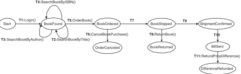
Following our previous work [5], we choose to specify the conversation model of a Web service as an extended state machine, where states denote the different logical stages in which a service could be in its interaction with a client, while transitions among states occur (mostly, but not only) as a result of operation invocations. Figure 1 presents an example of a simplified conversation model supported by the Web portal of a bookseller. States are labeled with a logical name, such as BookFound, BookOrdered. Transitions are labeled with events corresponding to operation invocations, such as Login or OrderBook.
Furthermore, transitions are extended beyond the traditional state machine model to capture abstractions that are necessary to model Web service conversa-tions, including activation and completion patterns. Activation patterns describe the triggering features of a transition (e.g., when the transition should occur).
Start BookFound BookOrdered BookShipped OrderCanceled BookReturned ShipmentConfirmed BillSent DifferenceRefunded T1:Login() T5:OrderBook() T6:CancelBookPurchase() T8:ReturnBook() T11:RefundPriceDifference() T10 T9 T7 T4:SearchBookByISBN() T3: SearchBookByAuthor() T2:SearchBookByTitle()
Fig. 1. Sample of aneBookShopservice conversation protocol
Completion patterns describe the implications and the effect of a transition from requester perspective (e.g., whether requesters can cancel an operation and what is the cancellation fee).
Activation Abstractions. In the extended state machine model, besides the fact that a transition is activated by invoking an operation, an activation property specifies an activation mode, activation event and pre-conditions. The activation mode indicates whether the triggering of the transition is explicit (mode=”user”) or implicit (mode=”provider”). When the activation mode is ex-plicit, the transition is activated by explicitly invoking a service operation. When the activation mode is implicit, the transition will occur automatically after the occurrence of a temporal event. A pre-condition is a triple (O-condition, U-condition, and T-condition), where:
◦ An O-condition specifies conditions on service objects (i.e., service request
parameters);
◦ A U-condition specifies conditions on requester profiles. It is used to specify
the fact that an operation can be invoked only by certain users (e.g., an operation is only available to “premium” customers);
◦ A T-condition specifies temporal constraints to allow the description of timed
transitions (e.g., a transition can occur only within a certain time period). We adopt XPath as a language to express queries and conditions. The defini-tions of temporal constraints use XPath time funcdefini-tions (e.g., current-time) and some predefined time functions in our model. In the remainder, begin(t) (resp., end(t)) denotes the beginning (resp., termination) date of the last invocation of the transition T within the same conversation instance. The conversation model features the following temporal predicates:
◦ M-invoke prescribes when an implicit transition must be automatically fired; ◦ C-invoke prescribes a deadline or a time window within which a transition
M-invoke is used to specify temporal events. C-invoke is used to specify tem-poral pre-conditions of a transition. Formally, a temtem-poral constraint is specified as either Pred(boolop,d), where Pred may be M-invoke, or C-invoke. boolop is a comparison operator (e.g., =, <, >) and d is either an absolute date time or a relative date time (e.g., begin(t)). The constraint M-invoke(boolop,d) is only authorized for implicit transitions and means that the transition is automati-cally fired when the condition current-time boolop d is evaluated to true. Here, current-time denotes the system time. The constraint C-invoke(boolop,d) means that the transition can be triggered only if the condition current-time boolop d is evaluated to true.
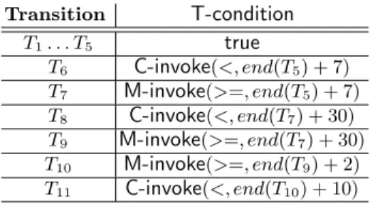
Table 1 illustrates temporal conditions of eBookShop conversation proto-col. For instance, the table shows that the operation associated to transi-tion T6 can only be invoked within 7 days after the completion of T5 (i.e.
begin(T6) < end(T5) + 7). The transition T9will be automatically performed 30
days after the completion of the transition T7(i.e. begin(T9) >= end(T7) + 30).
Table 1.eBookShopConversation time properties
Transition T-condition T1. . . T5 true T6 C-invoke(<, end(T5) + 7) T7 M-invoke(>=, end(T5) + 7) T8 C-invoke(<, end(T7) + 30) T9 M-invoke(>=, end(T7) + 30) T10 M-invoke(>=, end(T9) + 2) T11 C-invoke(<, end(T10) + 10)
Completion Abstractions. The completion property of a transition speci-fies the effect of a transition. With regard to this property, we distinguish the following types of transitions2
◦ Effect-less denotes a transition which has no permanent effect from the
client’s perspective. Canceling this kind of transition does not require the execution of any particular operation. For example, the transition T2, car-ried out during the execution of the operation SearchBookByTitle(), does not have any permanent effect, as far as the client is concerned;
◦ Compensatable denotes a transition which has an effect that can be undone
by explicitly invoking a compensation operation. A compensatable transi-tion is characterized by giving the name of the corresponding compensatransi-tion transition and its cancellation cost. Consider, for instance, the transition T7. The effect of this transition consists of transferring money from the client bank account to the provider account. However, the effect of this transi-tion can be (partially) undone (i.e., the client can be refunded) if the client
2 Other types of transactional properties are identified but not presented here due to
decides to return the purchased items (operation ReturnBook()). The tran-sition T8:CancelBookPurchase() can be used to compensate the trantran-sition T5:OrderBook();
◦ Definite denotes a transition whose transactional effects are permanent (i.e.,
are not compensatable). For example, after the delivery of the purchased items, the eBookShop.com service remains in the state BookShipped during 30 days, corresponding to the period of time where the user can, under certain conditions, return the purchased items (operation ReturnBook). After this period of time, the transition cannot be undone. This abstraction is conveyed by labeling the transition T9, for instance, as a definite transition.
2.2 Overview of BPEL
BPEL (Business Process Execution language) [3] is an XML-based language intended to specify processes that involve operations provided by one or several Web services. It can be used to define executable and abstract processes. An
abstract process defines a set of message exchanges between a Web service and a
client of the Web service, without revealing the Web service’s internal business logic. An executable process defines the service business logic based on a number of constituent activities, the partners involved in these activities, the messages exchanged between partners, and exception handling procedures.
An activity in a BPEL process is either primitive or structured. The types of primitive activity are: invoke, to invoke a web service operation; receive, to wait for a message from an external source; reply, to reply to an external source message; wait, to remain idle for a given time period; assign, to copy data from one variable to another; throw, to raise exception errors; and empty, to do noth-ing. Structured activities are defined using the following control flow constructs: sequence, for representing sequential order between activities; switch, for exe-cution conditional routing; while, for loop iteration; pick, for non-deterministic choices based on events; flow, for parallel execution routing; and scope, for grouping activities to be treated by the same fault-handler and possibly within a given transactional context.
Given a set of activities contained within the same flow block, control links, allow the definition of dependencies between two activities. The target activity of a control link may only start when the source activity has ended.
3
Generating Implementation Skeletons
from External Service Specifications
Now that the basic conversation concepts have been introduced, we show how ex-ternal service specifications can be used to generate inex-ternal specifications, that is, executable business logic. The basic idea consists in generating a service im-plementation skeleton starting from the service interface (specified for instance in a WSDL document) and from a protocol specified with the model described above. The skeleton includes code that maintains the conversation state and
checks whether messages are received and sent in accordance with coordination protocol definitions, returning an error to the client if a message is not compliant. It has constructs for receiving service invocation messages, detecting transition activation events (such as explicit operation invocations or temporal events for implicit transitions), triggering transitions, and ensuring that the implications and effects of transitions are performed in accordance with the defined coordina-tion protocol. In a nutshell, the skeleton implements what we call conversacoordina-tion
management logic.
The skeleton does not include any service-specific business logic, i.e., it does not include information on how the individual operations are implemented. Oper-ation invocOper-ations appear as black boxes in the skeleton, and it is up to the service developer to extend the skeleton by refining the implementation of each of the operations. The benefits of the model-driven generation is that developers “sim-ply” focus on implementing the internal business logic. The code for managing the conversation state and verifying compliance of messages with conversations is automatically generated, thereby considerably simplifying the development.
The remainder of this section describes how the different aspects of a pro-tocol translate into a service skeleton. Although we will focus on the concepts behind this mapping, we endow these concepts with examples based on the use of the protocol model introduced earlier and of BPEL as service implementation language. The presentation revolves around the three logical steps of the trans-formation: first, we show how each transition is mapped into a process skeleton (called transition skeleton). Then, we show how each state is mapped into a state skeleton, which combines the skeletons of the transition in output to that state. Finally, once we have defined how individual states and transitions are mapped, we show how the state skeletons are linked together into an overall process skeleton, based on the overall graph topology of the statechart.
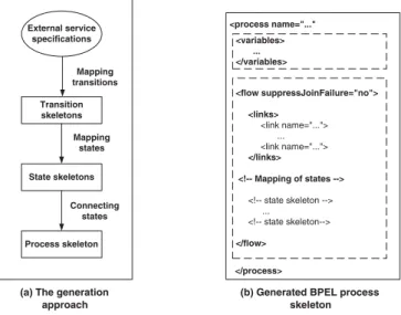
In BPEL terms, we follow the generation approach depicted in Figure 2(a): A service protocol is transformed into a BPEL flow of activities (the state skeletons, Figure 2(b)). To preserve and enforce the overall conversation model, that is, to enforce the semantic of the whole protocol, state skeletons are linked together using BPEL links.
3.1 Mapping Transitions
Transitions in the protocol definition are mapped into transition skeletons that 1) check that the preconditions are met (generating a fault message in response otherwise), 2) execute the operation implementation logic (which will have to be specified by the designer), and 3) return a reply to the client, by sending a message corresponding to the operation output parameters.
Each time a transition t is activated from a state S where t is allowed, the corresponding skeleton of t evaluates the transition preconditions (T-condition, U-condition and O-condition in case of explicit transitions or U-condition and O-condition in case of implicit transitions). If all the conditions are true, then the skeleton proceeds by executing the operation implementation logic of the operation associated to t, and the result is returned via a <reply> activity to the
<variables> ... </variables> <flow suppressJoinFailure="no"> <links> <link name="..."> ... <link name="..."> </links> <!-- Mapping of states --> <!-- state skeleton --> ... <!-- state skeleton--> </flow> <process name="..." </process>
(b) Generated BPEL process skeleton (a) The generation
approach External service specifications Transition skeletons Process skeleton State skeletons Mapping transitions Mapping states Connecting states
Fig. 2. Process skeleton generation
client. The definition of the data flow, and specifically of which process variables flow into the receive activity (i.e., how the return values are determined), is to be done by the designer as it is part of the internal business logic, not part of the external specifications. If the preconditions are evaluated to false, an error message is returned to the client by an automatically generated (i.e. <reply>) activity that returns a fault. As we will see later when discussing state skeletons, if such conditions are false then the transition is still active (it has not been triggered, and therefore the conversation has not changed its state), and therefore we will need a looping mechanism to get back to the point where the transition can be triggered (e.g., by new operation invocations). We will discuss in the following how to map the fact that the transition is waiting for an operation invocation (or for a time interval to elapse) in order to be triggered, as the appropriate mapping for this depends not only on the transition, but on the characteristics of the state to which the transition belongs, as shown later in this section.
Furthermore, in the case of a compensatable transition, a skeleton of a com-pensation handler is generated in order to implement the comcom-pensation activ-ity of the transition. More precisely, a transaction begin/end block is trans-formed into a <scope></scope> BPEL block. If a transaction t is compensa-table, its compensation transition, say tc, is transformed into <compensate> BPEL construct. The skeleton of the compensatable transition t will contain a <compensationHandler> that will be executed if t is compensated, and that of the transition tc will contain a <compensate> construct that will be used to compensate t.
Finally, it is worth noting that transition activation patterns (e.g., explicit invocation message or temporal events) are not considered during mapping of
transitions but are dealt with during mapping of states. As explained in the next section, the reason of this choice is that the constructs generated to implement a transition activation patterns depend on the type of the state (e.g., a state with one or multiple output transitions). As a consequence of this choice, the generated transition skeletons are very similar for both implicit and explicit transitions.
3.2 Mapping States
This section shows how each state is mapped into a state skeleton by combining the skeletons of the transitions in output to the state.
<onMessage ...>
<!-- explicit transition skeleton --> </onMessage>
... <onMessage ...>
<!-- explicit transition skeleton --> </onMessage>
<pick createInstance="no">
<onAlarm until=...> <!-- implicit transition skeleton --> </onAlarm>
...
<onAlarm until=...> <!-- implicit transition skeleton --> </onAlarm> Mapping explicit transitions Mapping implicit transitions Synchronization relationships through links </pick > <while VS="false"> <target linkname=...> ... <target linkname=...> </while> <receive> ... </receive>
<!-- explicit transition skeleton -->
Mapping an explicit transition Synchronization relationships through links <while VS="false"> <target linkname=...> ... <target linkname=...> </while>
(a) Mapping states with one explicit output transition
(c) Mapping states with multiple output transitions <wait until= .../>
<!-- implicit transition skeleton -->
Mapping an implicit transition Synchronization relationships through links <while VS="false"> <target linkname=...> ... <target linkname=...> </while>
(b) Mapping states with one implicit output transition
Fig. 3. States skeletons
First, assume that a state S has only one output transition to, and that tois explicit. In this case, we want to express the semantics that when the conversa-tion is in state S, the transiconversa-tion is active and therefore the corresponding skeleton must be waiting for an operation invocation (i.e., for an incoming message to arrive). In BPEL, this means that the generated state skeleton will include a <receive> activity followed by the transition skeleton of to(Figure 3 (a)). If to
is implicit, then this means that the protocol semantics waits for a certain pe-riod to elapse before triggering the transition. This is expressed by introducing a delay node, represented by a <wait> activity followed by the implicit skeleton of to (Figure 3 (b)).
Consider now the general case in which a state S of a service protocol has
Then, since these transitions are in output to the same state, they are all active at the same time. Furthermore, only one at a time can be processed, since as one transition is triggered then the conversation changes state and therefore the other transitions need to be disabled. To enforce this semantic in BPEL, we place the activities sk1,sk2, . . . skn into a pick construct, that has as one onMessage statement for each explicit transition, corresponding to the operation input mes-sage for that transition, and one onAlarm statement for each implicit transition, corresponding to the M-invoke condition for that transition (c.f., figure 3(c)). Then, the remainder of the skeletons is placed into an activity which is invoked if the event (i.e., message or alarm) occur. The semantics of the pick is such that only one branch of the pick is executed, i.e., only one event is processed. This is what we want, as when an event is received, then it is processed and the conversation changes state, so that operation invocations corresponding to other transitions in output from the same state are not processed.
There is an exception to this rule in the case in which the invocation fails due to the fact that the activation condition is false. To cater for this case, the pick activities are inserted into a while construct where a state variable, noted
VS for the state S, that controls the loop is set to true at the start of the loop, and set to false if any of the activation conditions for the invoked operations are false (Figure 3).
We observe also that the reason for handling the simplified case (state with only one output transition) differently, although the general case cover the sim-plified one as well, is because in simple cases it is possible to generate simpler skeleton, that are easier to interpret for the developer and therefore easier to extend with proprietary business logic.
3.3 Handling Connections among State Skeletons
We now show how state skeletons can be linked together to express the seman-tics of the statecharts. This is the final step of this generation process. Due to space constraints, this section only gives an overview of the concepts used to handle connections among state skeletons, omitting some implementation de-tails, which are often specifics of this or that implementation language (e.g., for BPEL these include handling dead path elimination or the handling of loops in the statechart with an acyclic flow language). We begin the description by showing how state skeletons are linked together in the general case (i.e., states with multiple input/output transitions). Basically, this amounts to linking to-gether the different pick activities (along with their enclosing while loop), as shown in Figure 3(c)). This is done as follows: all while loops are inserted into a higher level flow statement. The dependencies among the states are modeled by links. Each state skeleton (i.e., each while loop) will have as many outgoing links as there are states connected in output, each going to the while skeleton corresponding to one of the output states. Each outgoing link is endowed with a link transitionCondition, automatically inserted by the mapper, that iden-tifies whether the flow should move to that state (i.e., should activate the while loop). The condition is based on variables, also automatically defined by the
mapper, that are set to true depending on which branch of the pick activity is executed, that is, depending on which transition has been followed and therefore on which state the conversation should go to. Note that the variables are set only of the invocation succeed, that is, only if the transition is actually followed. Note also that if a state has multiple incoming transition, then it will have multiple incoming links, which is consistent with the semantics of the protocol as a state is entered as any one of the input transition occurs.
Handling Special Cases. There are some special cases that require specific
treat-ments as they are not supported by the general approach described above. For example, in BPEL, self-transitions (i.e., transitions that end up in the same state) cannot be handled explicitly because BPEL do not support cyclic process graphs (e.g., in BPEL, links must not create a control cycle). However, such transitions can be handled using a condition in the while loop of a state, similarly to the case of invocation failures described in the previous section. Therefore, in case of self-transitions, the state variable VS that controls the loop is set to false even when the transition is executed correctly, thereby enabling a self-transition to return to its starting state after a successful execution of its associated operation. Also note that, just like for state skeletons, simplifications with respect to the general approach described above can be made for statecharts with simpler topologies. For example, if we have a linear statechart (each state has one in-put and one outin-put transition), then the linkage among state skeletons can be achieved by wrapping state skeletons into a sequence constructs. Again, these simplifications are dependent on the details of the selected execution language.
4
Generating Service Operation Implementation Logic
4.1 ConceptsInstead of generating the composition skeleton and then extending it with oper-ation implementoper-ation logic, the developer may take an alternative approach and start by first defining the implementation logic for each operation, and by then having the CASE tool generate BPEL (or otherwise) specifications that com-bine conversation management logic (the skeleton) with the specified operation implementation logic, up to the point executable specifications are generated.
This approach has advantages and limitations. On the plus side, it provides independence from the execution language (i.e., the one generated by the CASE tool and ultimately executed by the service composition engine). In fact, in the approach described in the previous section, the developer specifies the operation implementation logic in BPEL (by extending the skeleton). Instead, if the exe-cutable code is automatically generated, developers can use different languages to specify how each operation is implemented, independently of what language is supported by the composition engine. For example, they could use statecharts, Petri nets, activity diagrams, or BPEL. It will be up to the tool to then translate these specifications into BPEL (or into whatever execution language is selected). As CASE tools evolve, we expect that they will be able to provide more and more
flexibility in terms of support for a variety of operation specification languages (the ones developers use to specify the operation implementation) and for a va-riety of executable languages, to be able to generate specifications for several composition engines.
This approach is however not applicable in the general case, and this is why we discuss it separately. In fact, there are cases in which it is not possible to spec-ify the implementation of the different operations independently of each other. As an example, assume that a service interface includes operations
getCredit-CardNumber(), getExpirationDate(), and getName(). The service implementer
would like to specify that once both a credit card number, an expiration date, and a name have been entered, then operation verifyCredentials(), offered by an internal application or by a third party, is invoked. In this case, the imple-mentation logic for these three operations would consists of waiting until they have all been invoked (in workflow terminology, this implies the presence of an and-join), and then call the verifyCredentials() service. The operations can still be separately implemented, for example by having the three operation imple-mentations set variables once they are completed as well as check variables (to verify if the other two operations have been executed as well) before invoking the verification service. However, this may result in a cumbersome design, that gets overly complex as the level of interactions among operation increases.
This being said, we expect most of the operation implementations to be functionally independent (i.e., to share state information and data, but to be such that the business logic can be independently specified)3. After all, this is what is done when services are implemented in Java. Therefore, we believe that providing users with the opportunity of separately specifying implementation logic for each operation - in a language of their liking - and of then automatically generating executable specifications will turn out to be a very useful and widely applicable functionality.
As a final comment before showing a concrete example of how this automated generation achieved in our prototype system for a given specification and a given execution language, we stress that hybrid approaches are also possible. In fact, the operation specification language can be at different levels of abstractions. If the specifications are so detailed to be executable, then the CASE tool will directly generate executable specifications from the combination of protocol de-scriptions and operation specifications. Otherwise, if specification are at a higher level (e.g., they only contain the operations to be invoked and their execution dependencies, but not the data dependencies or how data is transferred from one operation invocation to the next), then the output of the CASE tool will still need to be refined, although the refinement is simpler as more can be done by the tool. This also enables a flexible mechanism for separating roles during develop-ment: for example, an operation can be fully implemented by a developer. In this case, a low-level operation specification language can be used. Otherwise, an ar-chitect may first want to define the operation implementation at a high level, to
3 Our framework, as well as the prototype implementation, allows for context to be
then let a developer fill in the details (including the inevitable platform-specific details). In this case, a high-level language will be best as operation specification language.
4.2 A Sample Mapping: From Self-Serv to BPEL
We now present a concrete example of the generation of the operation imple-mentation logic starting from the operation specification. Specifically, we will use as example the languages supported by our prototype implementation, de-veloped within the Self-Serv system [5]. As execution language, we use BPEL. As operation specification language, Self-Serv supports a variation of statecharts.
For ease of presentation, we abstract from the details of the Self-Serv spec-ification model, and present a simplified version here. In particular, we assume that an interface operation O can be implemented in terms of invocation of operation ox offered by service sy (denoted by the syntax O ≡ sy.ox). In this case, we call the operation O a singleton operation. Otherwise, operation O can be structured, and consist of the parallel or sequential invocation of other operations Oiand Oj. Sequential invocation of two operations Oi and Oj is de-noted by the syntax Oi ; Oj, while parallel execution is denoted by Oi || Oj. In turn, operations Oi and Oj can also be structured and be further decomposed, until elementary operations, corresponding to invocations of actual operations offered by a service interface, are reached. Examples of operation composition, and their corresponding pictorial representations based on the statechart model of Self-Serv, are shown in figure 4.
secureAccess .Login BestBookShop. ReturnBook CancelBook Purchase bookShop1.SearchBookByISBN bookShop2.SearchBookByISBN Operation Composition bookshop_1.SearchBookByISB(...) || bookshop_2.SearchBookByISBN(...) secureAccess.Login BestBookshop.Returnk(...) ; CancelBookPurchase(..) T1 Login T4 SearchBookByISBN T8 ReturnBook Corresponding statchart
Fig. 4. Operation implementation logic of 3eBookShopservice transitions
We now describe how the BPEL implementation skeleton is generated start-ing from the external specification and the operation implementation specifica-tion both expressed with the Self-Serv model. Note that we are still generating skeletons (although more complete than the ones of the previous section) since in this case the operation specification language is at a high abstraction level.
Table 2 presents rules used to generate the BPEL code of an operation given its specification. Moreover, in case the specified operation is associated to a compen-satable transition, the generation rules describe how the implementation logic of the corresponding compensating operations is generated.
Table 2. Composition Model generation rules to BPEL Entity Method BPEL construct
Internal invoke <!-- empty implementation logic -->
compensation <!-- empty compensation logic -->
Singleton invoke <invoke partner="Si" operation="opj" ../>
Si.opj compensation opjis related to aDefiniteorEffect-lesstransition inSiprotocol <!-- empty compensation logic -->
opjis related to aCompensatabletransition inSi protocol <invoke partner="Si" operation="opjc" ../>
Serial invoke <sequence>
OPj; OPk <!-- generating operation implementation logic of OPj -->
<!-- generating operation implementation logic of OPk --> </sequence>
compensation <sequence>
<!-- generating OPk compensation logic --> <!-- generating OPj compensation logic --> </sequence>
Parallel invoke <flow>
OPj||OPk <!-- generating operation implementation logic of OPj -->
<!-- generating operation implementation logic of OPk --> </flow>
compensation <flow>
<!-- generating OPj compensation logic --> <!-- generating OPk compensation logic --> </flow>
As the table shows, if an interface operation op associated to a transition t is a singleton operation, then the corresponding BPEL skeleton will include an
<invoke ../>activity to invoke the related operation opj of the service Si (see
table 2). If t is compensatable, the compensating operation of op, say opc, can be inferred automatically, but only if Si.opj is compensatable according to the conversation protocol of the service Si. In this case, the<compensationHandler>
of BPEL skeleton of t will contain an<invoke ../> activity to invoke the com-pensating operation of opj.
If an operation op consists of serial composition OP j; OP k, the correspond-ing BPEL skeleton will contain a <sequence></sequence> block of the
oper-ations OP j, OP k. The generation of the implementation logic of the opera-tion op is performed through a recursive analysis of its serial component op-erations. If the operation op is associated to a compensatable transition t,
of compensation operations of the component operations of op. The compen-sation operations should appear in the opposite order of the corresponding operations of the composition sequence. Note that since the operation in the
<sequence></sequence> block can be structured, this has to be recursed until
elementary operations are found, at which point the compensating operation of the invoked operation is determined from the protocol specifications of the invoked services.
Finally, if an op is parallel operation, the corresponding BPEL skeleton will contain a <flow></flow> block of the component operations. If the operation
op is associate to compensatable transition t, then the <compensationHandler>
<flow></flow>block of the BEPL skeleton of t will contain a the corresponding
compensation operations the component operations of op.
5
Discussion
The work presented in this paper discusses issues related to web service conversa-tion models and model-driven service development. With regard to first aspect, several efforts that recognize the need for extending existing service description languages to cater for constraints such the valid sequence of service invocations [7]. These include work done in standardisation efforts such as BPEL, WSCL (www.w3.org/TR/wscl10) and WSCI (www.w3.org/TR/wsci). Our work makes complementary contributions to the efforts mentioned above by endowing ser-vice descriptions with abstractions such as temporal constraints, implications and effects of service invocations.
With regard to the second aspect, it should be noted that model driven de-velopment of applications is a well established practice [8]. However, in terms of managing the Web service development lifecycle, technology is still in the early stages. We believe that the level of automation can be substantially increased with respect to what is available today, especially in terms of factorizing into the middleware those chores common to the development of many Web services. The approach proposed here has several advantages with respect to previous art, in-cluding early formal analysis and consistency checking of system functionalities, refinement and code generation. For example, the work proposed in [2] features generation rules from UML activity diagrams to BPEL processes. The work pre-sented in [9] focuses on generating executable process descriptions from UML process models. The contribution of our work is specializing the model driven approach to web service conversation and composition models. As mentioned before, our approach focuses on specifying service composition models along with the conversation definitions and generating the executable specifications of a service that not only implements the service operations as specified, but also guarantees of conformance of the service implementation with the conversation specification.
The framework presented in this paper has been implemented in a proto-type, built as an extension of the Self-Serv service development platform [6]. In particular, the prototype implements the generative approach where
con-versation models are specified using an extended state machine model as pro-posed in [4], composition models are specified using statecharts, and executable processes are described using BPEL. Through the tool, users can visually edit service conversations and composition models and automatically generate the BPEL skeletons, which can then be extended by the developers and even-tually executed using BPEL execution engine such as the IBM’s BPWS4J (www.alphaworks.ibm.com/tech/bpws4j).
This model-driven development framework is one of the components of a broader CASE tool, partially implemented, that manages the entire service de-velopment lifecycle. In fact, we envision a model driven service dede-velopment framework where various service functionalities such as composition logic, con-versation management, trust negotiation, security, and exception handling are specified using high level notations. Based on these notations, effective automa-tion of various aspects of service development activities will become a reality (e.g., formal analysis and validation of service composition models, generation of service composition skeletons, generation of conversation models and trust negotiation policies of composite services, etc). The development of this kind of framework and its supporting infrastructure is clearly a complex endeavor, likely to require further progress both in terms of research and of standardiza-tion. Our early results related to other parts of the model-driven generation approach, such as the details of the conversation model and the security/trust negotiation models can be found in [4, 11].
Our ongoing work involves the generation of conversation models starting from the composition model. Another line of research and development is related to the identification of what should be generated as part of the specification of the (composite) service and what should be instead embedded into the middle-ware. For example, the automatic generation of conversation management logic can be handled in two ways: one has been proposed in this paper, and involves the automatic generation of the service specification. Another approach consists in developing a separate middleware component, that we call conversation
con-troller, which is separate from the service implementation: it sits in between
clients and services and enforces protocol compliance, by maintaining the con-versation state and verifying that each operation invocation is in accordance with the conversation state and protocol definition. The two approaches have pros and cons. Having a middleware component is useful in that it hides com-plexity from the developer and manages protocols automatically, and can also provide such features as logging, monitoring, and analysis. It is also more robust to changes, as protocol evolution can be handled independently from changes to the detailed service specification. On the other hand, this approach requires yet another middleware component, which by the way is not available yet. Although not supported by the current prototype, the approach proposed here is anyway applicable to both scenarios, as the generation of the conversation management logic described in Section 3 can be used to feed specifications to the conversa-tion management middleware instead of resulting in extensible process skeletons. This requires modifications to the tool that are conceptually relatively simple
although implementation intensive. The benefits in terms of independence of the specific conversation management language supported by the tool would remain the same.
In summary we believe that, once the research and development work on the aspects described above has been completed, this approach will result in a comprehensive platform that can substantially reduce the service development effort and therefore foster the widespread adoption of Web service technology and of service-oriented architectures.
References
1. G. Alonso, F. Casati, H. Kuno, and V. Machiraju. Web Services Concepts, Ar-chitectures and Applications. Data-Centric Systems and Applications. Springer Verlag, 2004.
2. J. Amsden, T. Gardner, C. Griffin, and S. Iyenger. Draft UML 1.4 Profile for Automated Business Processes with a mapping to BPEL 1.0.
http://dwdemos.dfw.ibm.com/wstk/common/wstkdoc/services/demos/ uml2bpel/docs/UMLProfileForBusinessProcesses1.1.pdf, June 9, 2003.
3. BEA, IBM, Microsoft, SAP, and Siebel. Business Process Execution Language for Web Services (BPEL).
http://www-106.ibm.com/developerworks/library/ws-bpel/, May 5 2003.
4. B. Benatallah, F. Casati, and F. Toumani. Web Service Conversation Modeling: Cornerstone for e-Business Automation. IEEE Internet Computing, 7(6), 2003. 5. B. Benatallah, F. Casati, F. Toumani, and R. Hamadi. Conceptual Modeling of
Web Service Conversations. CAiSE’2003, 449–467, Klagenfurt, Austria. Springer. 6. B. Benatallah, Q. Z. Sheng, and M. Dumas. The Self-Serv Environment for Web Services Composition. IEEE Internet Computing, 7(1), January-February 2003. 7. J. Koehler, R. Hauser, S. Kapoor, F. Y. Wu, and S. Kumaran. A Model-Driven
Transformation Method. In Procs of EDOC 2003, Brisbane, Australia, Sept. 2003. 8. S. Mellor, A. N. Clark, and T. Futagami. Special Issue on Model-Driven
Develop-ment. IEEE Software, 20(5), 2003.
9. E. D. Nitto, L. Lavazza, M. Schiavon, E. Tracanella, and M. Trombetta. Deriving Executable Process Descriptions from UML . In IEEE ICSE’2002, Orlando, USA. 10. M. P. Papazoglou and D. Georgakopoulos. Special issue on service oriented
com-puting. Commun. ACM, 46(10):24–28, 2003.
11. H. Skogsrud, B. Benatallah, and F. Casati. Model-Driven Trust Negotiation for