Atomic and Molecular Ions with Photon Resonators
for Quantum Information Science
by
Molu Shi
B.S. Physics and Mathematics
University of Toronto, 2009
Submitted to the Department of Physics
in partial fulfillment of the requirements for the degree of
Doctor of Philosophy
at the
MASSACHUSETTS INSTITUTE OF TECHNOLOGY
September 2015
®
Massachusetts Institute of Technology 2015. All rights reserved.
Signature redacted
A uthor ...
...
Department of Physics
17
nAug
28, 2015
Signature redacted
C ertified by ...
...
Isaac L. Chuang
Professor, Departments of Physics and EECS
Thesis Supervisor
Signature redacted
Accepted by ...
...
Nergis Mavalvala
Professor of Physics, Associate Department Head for Education
VASCHUL TITUTEOF TECOOG
SEP
01
2015
Atomic and Molecular Ions with Photon Resonators for
Quantum Information Science
by
Molu Shi
Submitted to the Department of Physics on Aug 28, 2015, in partial fulfillment of the
requirements for the degree of Doctor of Philosophy
Abstract
With continued development of laser-atom interaction, systems of trapped ions offer a promising platform for the realization of fault-tolerant quantum information process-ing (QIP). Much progress with sprocess-ingle atomic and molecular ion qubits has been made both in theory and experiment on the fundamental building blocks for scalable QIP architectures. Nonetheless, difficulty still remains for quantum network implemen-tation and spectroscopy protocols for atomic and molecular ions, respectively. The objective of this thesis is to design and test the ion trap integration with photon res-onators, which can facilitate coherent ion-photon state transfer in quantum networks, and microwave spectroscopy for molecular ion rotational states.
The first part of the thesis describes a novel planar trap design with an integrated optical cavity. Proposals for photon number memory with trapped ions are presented, and experimental implementation for single ion cavity QED is explored. In addition, a study of vacuum-induced scattering loss increase is performed for mirror coatings at several temperatures and wavelengths, from which a method of retaining cavity finesse was developed.
In the second part, an experiment is proposed for microwave quantum logic spec-troscopy of molecular ions. With a cavity field to facilitate entanglement between co-trapped single atomic and molecular ions, a reliable and non-destructive spectroscopy method, as well as molecular ground state cooling can be realized.
Thesis Supervisor: Isaac L. Chuang
Acknowledgments
I owe my thanks to many people, without whom the thesis is not possible. I thank
my adviser Prof. Isaac Chuang, who introduced me to the field of quantum infor-mation science in 2009, and has continuously advised my research ever since, with patient guidance, inspiring insights, and secured funding support. It has been a great opportunity working with Ike to have the freedom to explore theoretical as well as ex-perimental aspects in quantum information science. I also want to express my thanks to Prof. Vladan Vuleti6 and Prof. Marin Soljaei6 as my thesis committee members, who offered insightful feedback on my projects. I need to thank Prof. Leonid Levitov as well, who has served as my academic adviser for six years and always pointed to me the right departmental resources when need.
The tremendous help I received from my lab mates must also be acknowledged.
I entered MIT with little experimental experience. Peter Herskind mentored me on almost every single aspect on how to become an AMO physicist, from soldering electronic components to operating an ion trapping experiment. Shannon Wang, Tony Kim and Paul Antohi were extremely useful resources for my training in linux and python programming, electronics, and mechanical design. I followed Yufei Ge and Shannon Wang through many trap fabrication processes, the experience of which lead to the recipe developed for the trap in my experiment. Many thanks should also
be given to my lab partner Michael Gutierrez, who I collaborated the most at MIT.
His dedication on most software development and the lab laser system maintenance is essential for our experiment. I should also thank Tailin Wu and Helena Zhang, who continue to make progress in our experiment with Michael in the past year. Lots of my insight in research also comes from helpful discussions with Amira Eltony, Jeff Russom, Hans H. Andersen, Anders Mortensen, Dorian Gangloff, Alexci Bylinskii, Adam McCaughan, and many students, postdocs, and faculties at MIT CUA. Special thanks should also be given to many technicians and staffs at CUA, NSL, MTL,
CMSE, Physics department, and many MIT machine shops for their friendly technical
I would also like to thank all my friends from MIT Fuyun Chinese Comedy Club,
for their strong supports during my founding and chairing period, and for their efforts in maintaining the club after I stepped down. I need to thank those who gave me invaluable help to recover from the health crisis in summer 2013, especially Su Wang and Mingyu Xue.
Of course, my deepest thank should be given to my parents, who encouraged me
to pursue education after high school in 2005, and supported me financially ever since. This thesis is dedicated to them, together with my wife Yi Wang, my other biggest discovery during my PhD.
Contents
I
Introduction
24
1 Introduction 25
1.1 Quantum information science . . . . 26
1.1.1 Qubit implementation . . . . 27
1.1.2 Network of quantum computers . . . . 28
1.2 Ion trap implementation . . . . 29
1.2.1 Atomic ions . . . . 30
1.2.2 Polar molecular ions . . . . 31
1.3 Thesis scope and contributions . . . . 32
1.3.1 Atomic ion and optical cavity . . . . 33
1.3.2 Molecular ion and quantum logic spectroscopy . . . . 34
1.4 Contributions of coworkers . . . . 35
1.5 Publications . . . . 36
2 Ion trapping fundamentals 37 2.1 Trapped ion dynamics . . . . 37
2.1.1 Paul traps . . . . 38
2.1.2 Surface electrode traps . . . . 41
II
Atomic ion and optical cavity
44
3 Theory of ion-photon interaction 45
3.1 Cavity Q ED . . . . 45
3.1.1 Ham iltonian . . . . 46
3.1.2 Effect of decoherence and optical Bloch equation . . . . 48
3.2 Quantum Network . . . . 50
3.2.1 Ham iltonian . . . . 52
3.2.2 Network photon and quantum Langevin equation . . . . 52
3.2.3 Approach to determine g(t) for deterministic quantum mapping 53 3.2.4 Requirement for implementation . . . . 55
3.3 Two ion quantum node . . . . 56
3.3.1 Mapping between single photon to collective two ion states . . 57
3.3.2 Mapping between single ion to collective two ion states . . . . 58
3.3.3 Pulse sequence . . . . 59
3.3.4 Generalization to multiple ions . . . . 63
3.3.5 Requirement for implementation . . . . 65
3.4 Two-ion experiment design with "5Sr+ qubit . . . . 66
3.4.1 SSr+ Qubit and vacuum stimulated Raman transitions . . . . 66
3.4.2 System design and evaluation . . . . 68
3.5 Conclusion and discussion . . . . 73
4 Mirror trap and microcavity ion trap system 75 4.1 D esign . . . . 76
4.1.2 Trap . . . . 4.1.3 Assembly . . . . 4.2 Trap fabrication . . . . 4.2.1 Evaporated trap . 4.2.2 Electroplated trap 4.3 Laser-machined micro-mirrors 4.3.1 Fabrication . . . . 4.3.2 Characterization . . . 4.4 4.5
System and trapping demonstration . Conclusions and discussion . . . .
5 Cavity finesse degradation and recovery in HV systems
5.1 M odel . . . .
5.2 Experim ent . . . .
5.2.1 Experiment setups . . . ...
5.2.2 Method of finesse decay measurement . . . .
5.3 R esults . . . .
5.3.1 Loss increase . . . ... . . . . 5.3.2 Recovery with Oxygen . . . .
5.3.3 Photocatalyzed recovery process . . . . 5.4 Surface Material Dependence and Passivation with SiO2
5.5 Conclusions and discussion . . . .
. . . . 78 . . . . 8 0 . . . . 8 3 . . . . 8 3 . . . . 8 9 . . . . 9 3 . . . . 94 . . . . 9 4 . . . . 9 7 . . . . 100 103 104 106 106 110 113 113 115 117 118 120
III Molecular ion and cavity assisted microwave
QLS
6 Quantum logic spectroscopy
6.1 Spectroscopy protocol . . . . 6.2 Ground state preparation . . . .
6.3 Conclusions and discussion . . . .
7 Molecular ion qubits and microwave QLS
7.1 Rotational state qubit in polar molecular ions . . . . . 7.2 Microwave QLS for molecular ions . . . .
7.2.1 Experiment design with SrCl . . . ..
7.2.2 Effective Lamb-Dicke parameter . . . .
7.2.3 Decoherence induced by off-resonance laser field
7.3 Conclusions and discussion . . . .
8 Conclusion and future work
A Characterization of Fabry-Perot cavities
A.1 Lorentzian mapping . . . .
A.2 Free decay spectroscopy . . . .
A.3 Ring down spectroscopy . . . .
B Separation of molecular rotational dynamics
B.1 Born-Oppenheimer approxiration . . . . B.2 Nuclear motion . . . . B.3 Rotational states . . . . 123 . . . . 124 . . . . 128 . . . . 132 135 137 139 139 143 150 151 153 155 157 157 158
from full Hamiltonian159
. . . . 159 . . . . 16 1 . . . . 162
List of Figures
1-1 (a) Schematic showing a linear ion chain confined in an ion trap (linear Paul trap) consisting of four RF electrodes and two end-cap (DC) elec-trodes. A laser beam is shown to address a single ion qubit transition.
(b) Camera images of few ions. Images by courtesy of University of
Innsbruck. ... ... ... ... 29
2-1 (a) Standard linear Paul trap geometry. The cross-section of the trap electrode inner surface forms a hyperbola defined in Eq. 2.1. With DC and RF potential applied on the electrodes, ions can be confined in the x-y plane at the hyperbolic center. Confinement in the z-direction can be realized using DC voltage end caps. (b) With the electrodes reconfigured on the same plane (top electrode removed, and potential at infinity is taken at zero DC), similar quadruple field for trapping can be realized. . . . . 38
3-1 Schematic of a cavity QED system. A single ion is trapped at the mode waist of a cavity field, with which the internal transition is at resonance, at coupling strength g. The decoherence rate of the cavity and ion is denoted K (See Appendix A for definition) and F, respectively. . . 46
3-2 Level diagram of the coupled ion-photon system. On the left and right, are the level diagrams of a non-interacting, and resonant cavity ion system, respectively. For the latter, the frequencies satisfy wc ~ WA. With coupling strength g, the degeneracy in each manifold is lifted by 2\/ng, resulting in a Rabi doublet. . . . . 47
3-3 Level diagram involved in Purcell effect modeling using optical Bloch
equation. A single photon excitation is involved in a cavity QED sys-tem. State 11) =
I
t,O) and 12) = 4,1) are coupled via a Rabifrequency QR, and both decay to 13) = 4,0) at rate F and r, respec-tively. . . . . 49
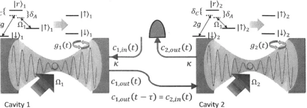
3-4 Schematic of a deterministic quantum network for single ions. The two nodes in the network consist of trapped ions, which couple to a flying qubit via a coherent mapping to photons in optical cavities as the quantum interconnects. Photons bearing the state from ions in cavity 1, transmit through the photonic channel between the two nodes (represented by the field operator ci,0ut(t) and c2,in(t)), and are mapped to the state of the ion iii cavity 2. To maximize the coupling fidelity, the coupling strength g1,2(t) needs to follow a particular time
dependent pattern. This is facilitated by coupling the ion state
4)1,2
and 1 t)1,2 using a Raman scheme via a state Ir)1,2, which gives a tunable effective coupling strength g1,2(t) to the cavity field. . . . . . 51
3-5 Schematic showing the cavity QED system with two ions, as the quan-tum interconnect for a two-ion node. (a) two ions are trapped in sym-metry with respect to the cavity field spatial profile, which are indistin-guishable to the field. A Raman scheme is employed so that a tunable cavity-ion interaction can be realized as in Sec. 3.2. The wave vector for the cavity and Raman beam is labeled ko and kc, respectively. The angle between kc and the ion chain axis is labeled 0. (b) with a laser directly addressing the 1
4)1,2
-+ 1 T)1,2 transition, phonon excitationIn) in the ion's motional state can couple to the two ion collective state via sideband transitions. The carrier transition Rabi frequency is labeled QL . . . . .
.. . .. ... . ..-.. . .. .. . 57
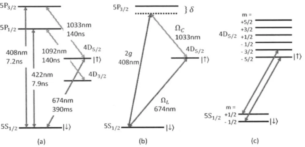
3-6 Atomic level structure for SSSr+ qubit implementation. (a) Wave-lengths and decoherence time for relevant qubit operating transitions. Qubit transition is implemented on the 674 nm 5S1/2- 4D5/2 quadruple transition. The 422 nm S1/- P1/2 dipole transition is used for Doppler cooling and qubit detection. If the ion is in the
I 4)
state, it can scatter Doppler photons from an incident 422 nm laser, which can be detected through a PMT. Otherwise the ion remains dark. The 1092 nm laser is used to repump the population from 4D3/2 state to ensure Dopplercooling and detection efficiency. The 1033 nm laser is used to pump states from I
4)
toI
t)
via the 5P3/2 state for qubit initialization. The 408 nm laser is the used for the Raman scheme cavity coupling shown in (b). (b) Raman scheme and A structure chosen for cavity QED. Compared to Fig. 3.2 and Fig. 3.3, the 5S1/2, 4D5/2 and 5P1/2 stateare used for 1
4),
1 T) andIr),
respectively. For simplicity, we use the same detuning for the cavity and Raman transition, i.e. 6C = 6A = 6.(c) Magnetic sublevels for qubit transition. Due to Zeeman splitting, the qubit transition is chosen to be the transition between 5S1/2,7j=-1/2 and 4
D5/2,.nj=-5/2. The population in 5S,/2,.,,=1/2 is pumped out via
3-7 Schematic of the cavity trap design. A planar ion trap is inserted between two curved cavity mirrors, which form a cavity mode through the central aperture of the trap. The cavity is designed such that the ROC for the bottom and top mirror follows R2 < R1, and the cavity
length L satisfies R1 < L < R1 + R2. In such case, the cavity waist, and hence the ion position is much closer to mirror 2, which contributes predominantly to the dielectric surface charging noise. This noise can be minimized by the shielding effect provided by the trap aperture, which can be made as small as close to the scale of the cavity waist (limited by the cavity clipping loss). In place of the single ion depicted, a two-ion chain can be formed along the trap axis, orthogonal to the cavity axis, allowing for the implementation of configuration in Fig. 3.3. 69
4-1 Schematic of the cavity trap design with flat bottom mirror. A planar ion trap is fabricated directly on a high-reflectivity mirror substrate, with an aperture left on the central ground electrode. Through the aperture, a cavity field is formed between the mirror substrate and another curved mirror above the trap, for which the waist is on the fiat mirror surface. With a low trapping height satisfying h.
<
zo,the Raleigh range of the cavity mode, the ion is close enough to the cavity waist to realize strong coupling. In such case, the dielectric surface charging noise comes predominantly from mirror 2, and can
be minimized by the shielding effect from trap aperture, which can be
made as small as close to the scale of the cavity waist (limited by the cavity clipping loss). . . . . 76
4-2 Segmented trap design. A mirror trap design is shown to scale (except ions). The segmented trap design can avoid possible contamination from oven flux, by separating the loading cavity zone. Shuttling of the ion can be implemented by varying the DC electrode voltages after the ion is trapped. . . . . 78
4-3 Schematic of mirror trap design. The trap electrode configuration is shown on a 0.5 inch high reflectivity mirror as the substrate for fabri-cation. The electrode widths are optimized such that Wb - 1.2W, and
Wd = 4wa according to Ref. [Hou08. The electrode gap size satisfies dq < wa.. . . . . 80
4-4 Assembly design of the cavity trap system. (a) the assembly design. The base plate holding the system is shown mounted in a 4.5 inch vac-uum chamber via groove grabbers, with Vespel SP3 spacers in between. The mirror trap packaged with an adapter is shown mounted at the center of the base plate. The upper cavity mirror connected to a piezo-electric tube (pzt) is aligned with the mirror trap via a tripod mounted on the base plate. (b) and (c), the two normal modes of the base plate
and cavity tripod system, which strongly couple to the cavity length. The resonant frequencies are 23.9 kHz and 36.4 kHz, respectively. . . 82
4-5 Schematic of mirror trap fabrication with c-beam evaporation. (a) a high reflectivity mirror substrate is prepared for fabrication. (b) a layer of photoresist is spin-coated on the mirror surface. (c) using contact exposure followed by resist development, the photoresist is patterned for trap electrode configuration, where resist remains along the trap gaps. The angle 6 is an important feature for lift-off resist, which avoids lateral metallic coating, and thus makes the lift-off step easy, as illustrated in (d) and (e). (d) with e-beam evaporation, metal elec-trodes form on the mirror surface following the resist pattern. (e) after lift-off, the resist in the trap gaps are removed. . . . . 84
4-6 Trap RF breakdown and its correlations to bubbled metallic edges.. (a) RF breakdown observed for evaporated mirror traps with an R.F sig-nal (approx. 200 VP, and 20 MHz) applied across the electrodes under vacuum, as observed with a CCD camera. (b) SEM picture of a typical electrode edge, which does not exhibit breakdown. (c) SEM picture of a typical electrode edge, which exhibited RF breakdown. Compared with (b), we found a region (500 nm width) with clusters of small metallic bubbles along the electrode edge. (d) SEM picture showing he same patterns in (c) found on samples fabricated for experiment in Ref. {tWS+11], which were tested with no breakdown characteristics.
(e) SEM picture showing the metallic bubbles found near the
photo-resist. (f) SEM picture showing the lift-off resist undercut and the
region of observed bubbles (c.f. Fig. 4.2.1-c,d). (g) SEM picture
show-ing resist coated by a metal layer from the lateral directions, makshow-ing it difficult to lift off. (h) back side illuminated microscope image, show-ing a typical failed sample from lift-off with metallic coatshow-ing resemblshow-ing that in (g). Lightened lines are the electrode gaps. . . . . 88
4-7 Schematic of mirror trap fabrication with electroplating. (a) a high reflectivity mirror substrate is prepared for fabrication. (b) a layer of silver seed layer is coated on the substrate. (c) photo resist is patterned on the seed layer in the lithography step, where resist remains along the trap gaps. (d) with electroplating, gold electrodes form on the seed layer following the resist pattern. (e) the photoresist is removed using solvents. (f) the silver seed layer uncovered from the resist removal is etched away with solution to which gold is inert to. . . . . 89
4-8 Packaged electroplated trap. (a) Microscope image showing a sample of gold electroplated mirror trap. (b) Mirror trap packaged in the mirror adapter mount, with breakout boards shown to which the trap electrodes are wire-bonded to. Inset of (b) Low profile wire bonds for laser access to ion height at 150 /tm above trap surface. . . . . 92
4-9 Micro-mirror fabricated using laser melting. (a) microscope image of a micro-mirror. The arrow shows the direction along which a profile measurement is taken. Due to the camera and profiometer needle mis-alignment, the the cross section is off-set to capture the deepest profile of the sample. (b) A calibration curve is given for ROC as a function of pulse frequency (c) A typical priflometer measurement result for mirror ROC characterization. . . . . 95
4-10 A typical transmission through the Fabry-Perot cavity formed with a micro-mirror and a flat, well characterized commercial mirror from
ATF. The cavity length is scanned during the measurement, and the
incident laser frequency is modulated with an EOM. Cavity loss can
be obtained by fitting the obtained transmission curve with Eq. 4.8.
Shown also, is the residual plot for this fitting. . . . . 96
4-11 Schematic of the laser delivery and imaging optics setup. (a) laser delivery setup for ion trapping (See Fig. 3.4.1 for "8
Sr+ level structure).
(b) imaging optics outside the chamber. . . . . 97
4-12 Scattering loss increase characterization over oven loading. (a) scat-tered photons from photo-ionization laser (461 nm) intersecting oven flux. To characterize the scattering loss increase due to oven flux con-tamination, a high reflectivity mirror is installed in place of the trap shown. Scattering loss before and after oven loading is measured at several spots along the trap axis. (b) mirror scattering loss compar-ison between cavity and loading zone, before and after running oven
flu x . . . . . 98
4-13 Doppler scattering spectrum of a stably trapped ion. The pzt voltage on the filtering cavity of the 844 nm laser (x-axis) is used to control the frequency detuning of the Doppler laser. The scattering intensity is measured by the PMT photon counts shown on the y-axis. A CCD camera image of the trapped ion is shown in the inset. . . . . 99
5-1 (a) Schematic of the experimental setup for chamber I. A pair of mir-rors forming a high finesse cavity with either Ta205 (coating I-1) or SiO2 (coating 1-2) as their surface layer, are placed in high vacuum.
Light from a single mode laser at 370 nm is used to probe the cav-ities as the laser frequency is slowly scanned linearly by a function generator. The transmitted light from the cavity is incident on an avalanche photodiode (APD). The laser frequency is also modulated
by a fast square-wave signal, which results in an intensity free-decay
of the cavity's transmitted light each time the slow scan brings the laser to resonance with the cavity (time = 0 ps). (b) Schematic of the experimental setup for chamber III. Two pairs of mirrors forming high finesse cavities with SiO2 (coating 111-2) and Ta205 (coating III-1)
as their surface layer, respectively, are placed in high vacuum. Light
from a single mode laser at 422 nm is used to probe the cavities as they are scanned by piezo-electric transducers (PZT). The transmitted light from each cavity is incident on an avalanche photodiode (APD). When the cavity becomes resonant with the laser, and the signal intensity reaches a defined threshold in a comparator, the laser light is switched to be of-resoniat with an accousto-optic modulator
(AOM)
(time0 ps), resulting in an intensity free-decay of the cavity's transmitted
light. (c) A typical intensity free-decay curve measured for 370 nm (coating I-1), fitted with an exponential model with a time constant of T = 411 us. . . . . 107
5-2 (Coating I-1) Loss increase over time at various temperatures, as sep-arate panels on a linear scale (a) and combined on a log-log scale (b):
210C, 500C, 750C, 100'C, 150'C (chamber I); and 33'C (chamber II)
The observation time range is different for each temperature data set, ranging from a few days (1000C) to a few years (330C). Each data
set is fitted with an exponential model shown as a solid line (a, b), weighted by the inverse variances of the data points. The exponential time scale is very sensitive to temperature. Error bars are statistical and correspond to one standard deviation (smaller than the size of the data symbol when not shown). . . . . 112
5-3 (Coating I-1) Logarithm of loss increase time scale, from an exponential fit (Fig. 5.2.2), against temperature. We fit ln(rth) with a model of the form a/(273 + T) + b to all data points (red solid line); the fitted
values are a = 7000(1500)K and b = -13(4). We also fit ln(Tth) with
a linear model (black dashed line) and obtain a negative slope of 1/e per 19(5)0C. The fits are weighted by the inverse variances of the data
points. Brackets and error bars indicate a 68% confidence interval on the fitted values. . . . . 113
5-4 Optical loss increase observed in chamber III for an optical cavity com-posed of mirrors with coating 111-1 (422 nm, Ta205 surface layer) at
57'C. With the current data, we do not have a good explanation for
the initial slow loss increase, which is observed only in this data set. It could be attributed to the thermal relaxation time of the mirror, whose temperature was monitored on the mirror mount, which is connected to the mirror via a ceramic piezo tube. Error bars are statistical and correspond to one standard deviation. . . . . 115
5-5 (Coating I-1) (a) Recovery with oxygen at 21'C, following the data set at 21'C (Fig. 5.2.2). Oxygen at a partial pressure of 10-2 Pa gives a barely statistically significant recovery (blue squares), while the atmo-spheric pressure of oxygen (red diamonds) gives full recovery to initial loss level (dashed line). (b) Recovery with atmospheric pressure of oxy-gen at 21'C (blue squares) and 150'C (red diamonds), following a loss increase at a much higher temperature of 150'C (data not shown). The recovery is slower and does not reach the initial loss level (dashed line).
Error bars are statistical and correspond to one standard deviation. . 116
5-6 (Coating 111-1) Laser-assisted loss recovery processes observed in cham-ber III. (a) loss recovery process examined during both illuminated and non-illuminated periods. (b) recovery rate obtained by fitting data in (a) using a linear model, and compared for both the illuminated and non-illuminated periods. (c) optical loss fully reversed in a continuous illumination process. We fit an exponential model and find the time constant to be 56.5 hrs. Error bars are statistical and correspond to one standard deviation. . . . . 117
5-7 Loss vs time for different mirror top layer coating: (a) Loss increase at 57 C measured at 422 nm for top layers: Ta205, coating 111-1 (red circles, data also shown in Fig. 5.3.1), and for 110 nm SiO2, coating
111-2 (blue diamonds). The dashed line is a linear fit with a slope of
-0.005(2) ppm/ h. (b) Loss at 100'C measured at 370 nm for top layers:
Ta205, coating I-1 (red circles), and for 1 nM SiO2, coating 1-2 (blue diamonds). The dashed line is a linear fit with a slope of 0.23(3) ppm/h. Error bars are statistical and correspond to one standard deviation. . 119
6-2 Summary of the quantum logic spectroscopy protocol. Green: initial ground state preparation via projection measurement for a single spec-troscopy ion and detection ion pair. Purple: specspec-troscopy procedure starting with system initialized to spectroscopy ground state. State re-initialization is achieved using projection measurement. The index
j
refers to thejth
cooling cycle after failing in projecting the mixed rotational state onto a pure state 1j - 1)s . . . . 1297-1 justification = justified . . . . 142
7-2 (a) Effective LDP produced by spatially varying laser field for three different scenarios, all at wavelength A = 1 im. Red: focused laser beam, wo = 2 pm. Green: retro-reflected laser beam, wo = 20 pm. Blue: Cavity laser beam, wo = 100 pm, cavity finesse, F = 1000. (b) Estimate of spontaneous-Raman-rate-to-Rabi-frequency ratio. Raman scattering rate is estimated using 10-'x Rayleigh rate, for travelling and standing waves, both at wavelength A= 1 pm. . . . . 150
List of Tables
3.1 Experiment parameters for two ion photon memory experiment . . .
4.1 Experiment parameters for micro-cavity experiment . . . .
5.1 Summary of experimental parameters and results. . . . .
5.2 Summary of experiment settings for sputtering process. . . . .
7.1 Experiment parameters for microwave QLS spectroscopy on molecular rotations . . . . 74 81 108 109 140
Part I
Chapter 1
Introduction
Ever since man wrote down their first equations, it has become an integral part of human nature to describe the observed with mathematical models, and to predict the unknowns through computation. With continued expansion of the horizon of the explored mathematical world, the scale and complexity of computation, and hence our desire for faster and more reliable computational tools escalates as well. On the other hand, the investigation in new computational technologies never stops. Each breakthrough in algorithm or computational hardware development in the history has always triggered revolutionary advancement in all scientific fields. Today, as the world enters the information era and our exploration of nature moves into the quantum level, the demand of computational power has again quickly exponenti-ated [Fey48]. Although much effort remains to improve the current computational architecture [Chu36, Tur38, Sha48j and the efficiency of electronic computers still grow promisingly as Moore's law[Moo65, many researches have focused on exploring new ways of computing.
As one most promising model, quantum computing is shown in many cases, to
be able to result in exponential faster algorithms than those based on electronic
computers. The key difference underlying this intriguing advantage lies in the new way information is encoded in quantum computers. Unlike in electronic (classical) computers where a bit assumes two states, a quantum bit (qubit) is represented by
a unit vector in a two dimensional complex plane. Quantum information encoded
in an n-qubit system therefore lives in a 2r-dimensional complex space spanned by the tensor product of n qubits. Compared to the 2" memory of an n-bit classical computer, the encoding in this much richer space also allows for the possibilities of new efficient algorithms.
With the concept proposed to efficiently simulate quantum mechanical systems [Fey48, Llo961, quantum computing has found potential applications in many fields such as database search [Gro97], factoring of large numbers [Sho83I, and systems of lin-ear equations [HHL09]. On the other hand, tremendous efforts have been made to search for the optimal implementation of quantum computers. Different proto-types have been constructed from a variety of quantum systems, including quan-tum optics [CY95, O'BO7], nuclear magnetic resonances [GC97, VSB+01J, Joseph-son junctions [MOL+99, MNAUO2], neutral atoms [BCJD99, ALB+071, and trapped atomic [CZ95, WMI+98 and molecular ions [DeM02, YN13. The goal was not only to realize the advantage in processing efficiency for a single quantum computer, but also to implement a scalable quantum network, with reliable interconnections allowing for communications among individual computers.
This thesis investigate two models in quantum computing systems, trapped atomic and molecular ions, and the use of photon resonators for quantumn interconnect im-plementation and qubit operation improvement. In this chapter, we give a brief introduction to quantum information science using trapped atomic and molecular ions, and outline the scope of this thesis.
1.1
Quantum information science
Quantum information science (QIS) seeks to construct a new information architecture based on the law of quantum mechanics, for computation and communication. Similar to electronic computers, the most elementary component of a quantum computer is a binary register, called a quantum bit, or for short, a qubit. This conceptual binary
register is composed of two discrete quantum levels
I
4) andI
T), which in general,can be thought of as any two level system such as the two polarization states of a photon
1CY951,
or two spin states of a nucleus [GC971. Binary (or gate) operations on qubits are facilitated via their coupling to external excitation, which flips the qubit state fromI
4) to IT)
and vice versa. For instance, in the case of a nuclear or photon qubit, qubit flips are done through polarizing optics, and resonant magnetic field coupling, respectively. A wave function14')
for this two-level system can be written as a superposition ofI
4) andI
T):
4')
=I 4)
+ e*i3I 4),
(1.1)where the information is encoded in the complex plane spanned by the relative phase
e'O. For multiple qubits, the total wave function
IT)
is represented by the tensorprod-uct of wave functions for each individual qubits, resulting in a 2" dimensional space for information encoding. Because of this new representation of information, many efficient algorithms for applications inaccessible by classical information processing
have been discovered [Fey48, Sho83, Llo96, Gro97, HHL09].
1.1.1
Qubit implementation
While quantum computers offer exciting advancement in information science, the experimental implementation can be quite challenging. Although conceptually, all two level systems can be considered as qubits, the way they can respond to external fields set further benchmarks to their candidacy for experimental implementation. On one hand, because of undesired coupling to environment noise (decoherence), most two level system approximations are only accurate within the excited state life time (decoherence time). To reduce computational errors in this time frame, desired quantum systems should use minimal time for computation relative to de-coherence. On the other hand, coupling to a third stable quantum state might be necessary in many systems, to allow for measurement to distinguish the binary states
com-piled in R.ef. [DiVOO], based on which different quantum systems have been proposed and tested for qubit implementation. This includes for instance, polarization states of photons [CY95, O'B07], spin states of nuclei [GC97, VSB+01j, phase and flux states in Josephson junctions IMOL+99, MNAU02I, and assemble states of atom clouds [BCJD99, ALB+07]. In Sec. 1.2, we explain in particular the implementation with trapped atomic [CZ95, WMI+98 and molecular ions [DeM02, YN13j.
1.1.2
Network of quantum computers
Similar to a conventional computer network, a quantum network consists of three parts: 1) quantum computers as the network nodes, 2) quantum channels for infor-mation transmission, and 3) interconnects between the computers and interconnects to map information between stationary and flying qubits. The importance for es-tablishing a quantum network is not only for long-distance quantum state teleporta-tion [BBC+931, but for its key role in distributed computateleporta-tion and secure communi-cation.
As in a classical computer network, distributed quantum computation provide Computing rurces equly ovxr the network, whesich Uvercom any cnsitraits imn
local quantum computers. Distributed computation also allows for more efficient information processing [CEHM99]. In particular, the overall space for information grows exponentially with the size of the quantum network, vs linearly in a classical computer network [KimO8J. While for a network of k classical computers, each with n bits of RAM, the total dimension of state space grows as k2", a quantum network with equal size can have a state space dimension of 2k".
Another advantage of a quantum network is that secure communication prototcol can be established for cryptographic key distribution [BB141. By randomizing the measurement bases of transmitted and received photon qubits, and confirming se-lected measurement results for common bases, eavesdropping activities can be faith-fully detected, and shared keys can be securely distributed.
1.2
Ion trap implementation
(a) (b)
Figure 1-1: (a) Schematic showing a linear ion chain confined in an ion trap (linear Paul trap) consisting of four RF electrodes and two end-cap (DC) electrodes. A laser beam is shown to address a single ion qubit transition. (b) Camera images of few ions. Images by courtesy of University of Innsbruck.
Trapped ions have now become one of the most promising qubit implementations for QIS. Figure 1.2 shows a schematic of atomic ions trapped in a Paul trap. In such architecture, ionized atoms or molecules are spatially confined in radio frequency (RF) electromagnetic fields. Qubit transitions are chosen between the ground and a meta-stable internal state of the ions. Coherent light sources are used to to facilitate qubit state flips, and to further reduce the ions' kinetic energy for stable confinement via Doppler cooling. The scattered photons from the ions during Doppler cooling can
be used for ion imaging and qubit state detection.
Because the trapped ion system can be enclosed in an ultra-high vacuum (UHV) environment (typically 10-10 - 10-1 torr), background noise disturbance to the
quan-tun system can be significantly reduced; and because of the stable spatial confine-ment, qubit state detection signals can be averaged over sufficient time to improve the signal to noise ratio (SNR,). Furthermore, the stable isotope structure allows for the replication of identical qubit copies, making it possible to construct a scalable quantum computing architecture. Since the advantage of trapped-ion systems are considered in the original proposal by Cirac and Zoller [CZ951, continued progress
has been made towards experimental implementations, with atomic and molecular ions, respectively. Because of the rich level structure in polar molecules involving vibration and rotational states, the techniques to manipulate both the internal and external states are quite different for atomic and molecular ions. We show the state-of-art proposals and experimental implementations for both systems in Sec. 1.2.1 and
Sec. 1.2.2
1.2.1
Atomic ions
Two types of transitions are commonly chosen for qubit implementation in atomic ion systems: electric quadruple, and magnetic dipole transitions (See for instance, Ref. [MSW+08] and Ref. [HAB+14J) 1. In both implementations, the Hamiltonian governing the laser-ion interaction are well characterized. For system scaling, 2D arrays [KMWO2 of trapped ions based on microfabricated ion trap chips [CBB+05] have been proposed, and the scheme of entangling adjacent ions via Coulomb interac-tions has implemented in various experiments with linear chains of ions [SKK+00, HHR+05I. Besides the qubit transition (internal) in trapped ions, the motional state (external) is usually involved in QIS, especially for ion entanglement opera-tions [Hom06]. Optical pumping and sideband cooling [DBIW89 are used, for the internal and external state initialization, with the state-of-art fidelity (see Ref. [NCOO]
for definition) of 99.991% [MSW+08] and 99.9% [RooO] achieved, respectively. As
a more accurate figure of merit for gate-to-coherent time ratio with all noise source included, the gate fidelity for both optical [MSW+08 and spin [HAB+14j qubits have been measured close to unity for single qubit gates, allowing for fault tolerant quantum computing [Shol. Because any multiple qubit gate can be re-expressed as a sequence of single qubit gates and CNOT gates [DiVOO], implementations of the two in many experiment such as Ref. [HAB+14, BHLL14 can sufficiently provide a universal set of quantum gates. Individual qubit addressing has been demonstrated in many ex-periment involving multiple trapped ions in linear chains as well [SKK+00, HHR+05].
For quantum network implementation, current experimental efforts focus on imple-menting proposals for both deterministic ICZKM97, KimO8] and probabilistic [DLCZO1I] approaches. For the former, photon resonators (usually Fabry-P6rot cavities) are
used as quantum interconnects between network nodes and channels. Mapping be-tween stationary (ion) and flying (photon) qubits is facilitated via strong coupling in the framework of cavity quantum electrodynamics (cavity QED, see Chap. 3). Although cavity QED has been demonstrated in photon resonators with ion crys-tals [HDM+091, single ion cavity QED still remains to be implemented. For the latter, projective measurement on the ion emitted photons over the network is used to generate heralded entanglement between ions. Although first experimental demon-strations [MMO+07j have low yields in entangled ion pairs due to limited light col-lection efficiency, continued progress has been made recently to increase the limit via
optical cavities [CSF+13, MRR+14I.
1.2.2
Polar molecular ions
The rotational states of molecules are promising candidates for qubit implementation. Continued progress on experimental verification of DiVincenzo criteria has been made since DeMille's proposal [DeM02]: Using a planer trap architecture, scalable quantum computing can be realized in similar ways as atomic ions, with qubit transitions ad-dressed by coherent microwave [SHDC13I or Raman [DM12, Leil2J laser sources, and ion-ion interactions facilitated via Coulomb forces. In terms of gate fidelity, on one hand, similar to atomic ion spin qubits, the microwave qubit level spacing for trapped molecular ions suggests a coherent time of several hundreds of ms [SBC+11]. In ad-dition, the small magnetic moments due to the large nuclear mass (opposed to that of electrons) also imply less sensitivity to magnetic field noise, compared to atomic ion spin qubits. On the other hand, a fast gate time (~ns) can still be obtained due to the permanent large dipole moment of polar molecular ions. Sec. 7.2.1 in Chap. 7 shows an example for SrCl+ molecules. Arbitrary single qubit rotations can be imple-mented via microwave addressing, and similar to atomic ions, Coulomb interactions
between trapped ions can be used for CNOT gate implementation, resulting in the bases for universal quantum gate construction. Two flying qubits are envisioned for polar molecular ion based quantum networks. For short distances (several meters), polar molecules can couple to single microwave photons in microwave cavities inte-grated to planar ion traps [SBC+11, Ant1ll, which can directly be used for remote entanglement generation. Although not specific to polar molecules, single microwave photon generation
1HSG+07],
detection [JRH+10, BLS+101, and remote qubit entan-glement generation [RSM+14] have all been demonstrated in experiments. For long distance, microwave photons can be converted to optical photons via e.g. an opto-magneto-mechanical quantum interface [XVT14], and transmitted through opticalfibers.
Although showing great promise for scalability, gate fidelity, universal gate and fly-ing qubit implementation, it is difficult to implement an efficient spectroscopy method for polar molecules for state initialization and detection. Several indirect spectro-scopic approaches are proposed [DM12, Leil2, SHDC13], but only a few realized in experiment {CGD+10]. Furthermore, due to the long wavelength of microwaves, in-dividual qubit addressing can be non-trivial. Raman lasers can be used in place of microwaves, which however trades off the compatibility of all-on-chip microwave integration.
1.3
Thesis scope and contributions
This thesis is outlined as follows:
Part I of the thesis presents an introduction to quantum information science and basic ion trapping technologies. In particular, besides the brief overview of QIS in the proceeding sections in this chapter, Chapter 2 describes the dynamics of trapped ions, and the coupling between the ion internal and motional states.
Part II and Part III present the thesis contributions to QIS with atomic and molecular ions, respectively.
1.3.1
Atomic ion and optical cavity
Part II of this thesis work contributes partial solutions to the following challenges for
QIS with atomic ions.
Two-ion quantum node for two-photon quantum memory
In a deterministic quantum network [CZKM97, KimO8], quantum state of single
pho-tons can be mapped to single ions via strong coupling in optical cavities. With multiple ions, not only can the ion-photon coupling be enhanced, the quantum state of multiple photon states can be converted and stored with ions. In Chapter 3, after a brief overview of the formalism of ion-photon interaction, we present an experiment design where using two ions, a two-photon quantum memory can be realized in the deterministic quantum network architecture. In particular, detailed pulse sequence and analysis of experimental feasibility with 8SSr+ ions are presented.
Microfabricated ion traps with optics integration
An important step towards single-ion-single-photon interconnect in an deterministic quantum network is to realize cavity QED for a single trapped ion. Although exper-imental demonstration on cavity QED has been achieved for ion crystals [HDM+09] and single neutral atoms[Kim98], it remains difficult for single trapped ions. To get a sufficiently large coupling efficiency in a stable cavity configuration, a close distance between ions and cavity mirror(s) is required. This can result in photo-induced charg-ing on the mirror dielectric surfaces, which can affect trappcharg-ing stability and induce undesired micromotions [WHL+111.
One possible solution provided in this thesis is a novel design of cavity-trap system. With a planer ion trap fabricated directly on a mirror surface, and leaving an small aperture on the central ground electrode, a stable short cavity can be formed with a waist of several microns. The ion exposure to dielectric material, and hence possible charging issues are minimized to the size of the aperture. With the promising results
from our proof-of-principle experiment at cryogenic temperature IWS+111, Chap. 4 in this thesis presents an implementation at room temperature, which avoids possible ion-cavity alignment during temperature cycles necessary for cryogenic systems, and paves the way for optical cavity integration.
Cavity finesse decay and recovery in high vacuum systems
Another challenge for ion-photon interfaces is to construct and maintain a high fi-nesse optical cavity in UHV systems. The state-of-art technology to fabricate high reflectivity mirrors for optical cavities uses Ta205 and SiO2 alternating dielectric layer
coatings, and typically finishes the coating with Ta205 for its higher index of
refrac-tion [Sit83, RTKL92. Evidence from many experiments have shown a scattering loss increase for this type of coatings under UHV [SLM+12, BMS+13, CBK+13, Cet1l], which can strongly affect QIS experiments. Moreover, no experiments have yet been performed to understand the scattering loss increase mechanism in such systems, nor to reverse the incurred loss efficiently.
In this thesis, we also constructed an experiment to study this loss mechanism under controlled vacuum pressure and temperature, and obtained result to support our hypothesis that tile incurred loss is due to oxygen depiction from surface oxices. An in-situ method to recover the optical cavity from the induced scattering loss as well. This experiment is presented in Chap. 5
1.3.2
Molecular ion and quantum logic spectroscopy
In part III of the thesis, partial solutions are given to the challenge of molecular ion rotational state spectroscopy.
For QIS with polar molecular ions, single ion rotational state spectroscopy (read-out and initialization) and individual ion addressing can be challenging, because of the lack of close transitions, and longer wavelength of microwave fields than typical ion spacing.
We proposed a scheme to use quantum logic spectroscopy [SRL+05] to overcome both challenges. When co-trapped with a single atomic ion, entanglement through their common motional bus can be used to map quantum states between the two. Therefore, readout and initialization of the molecule can be facilitated by heralded measurement on the atom. A spatially varying AC stark shift field by a laser field is used to enhance the internal-to-motional state coupling for the molecular ion. Fur-thermore, the switching of this field can turn on/off the inter-ion quantum state map-ping, and hence provide single molecular qubit addressing, despite the long microwave wavelength. This method can also be used for ground state cooling in molecular ion rotational states. The work is presented in Chap. 6 and Chap. 7.
1.4
Contributions of coworkers
All above works are completed through collaborations with my co-workers.
The project on optics-integrated traps was initiated by Peter Herskind based on David Leibrandt's original proposal, and Peter's leadership continued till the mid phase of the second half of the project - for tests at room temperature. Shannon Wang
led the trap tests for the first phase at cryogenic temperature. During the second
phase of experiment at room temperature, Michael Gutierrez designed and simulated the new trap, and together with Richard Rines, and Helena Zhang, provided great support in terms of maintaining the laser optics, pulse programmer, and other control software for the experiment. I also followed Yufei Ge to practice nanofabrication techniques till the early phase of the second experiment.
The work on cavity loss studies is completed through collaboration with the Vuleti6 lab. Dorian and his coworkers performed half of the experiment with cavities tested for coatings for 370 nm lasers. Michael Gutierrez helped to simplify the experiment complexity and programmed the first script to allow for automatic data analysis. Kai Aichholz helped to write the graphical user interface for one function generator control software. Tailin Wu operated part of the experiment with me, and is currently
leading the project for further studies.
The theoretical work of molecular ion spectroscopy was initiated by Peter, who for-mulated the framework of effective Lamb Dicke parameter generation. Prof. Michael Drewsen provided ideas to simplify the spectroscopy protocol.
My advisor Isaac Chuang contributed great insights, and initiated the
collabora-tions throughout all projects.
1.5
Publications
The following is a full list of my publications related to this thesis work.
1. D. Ganloff, M. Shi, et al, Preventing and Recovering from, Vacuum-induced Optical Losses in Ta205 Mirror Coatings, Vol. 23, Issue 14, pp. 18014-18028
(2015)
2. A. Eltony, D. Ganloff, M. Shi, et al, Technologies for trapped-ion quantum
in-formation systems, arXiv:1502.05739 (2015)
3. M. Shi, et al, Microwave quantum loqic spectroscopy and control of molecular ions, N. J. Phys. 15(2013) 113019
4. P. F. Herskind, S. X. Wang, M. Shi, et al., Microfabricated surface ion trap on
Chapter 2
Ion trapping fundamentals
Since its ground breaking experiments in 1950's for mass spectroscopy [Pau90], ion traps has provided breakthrough technologies for manipulation of single quantum particles [Winl3I. For trapped-ion quantum computers; stable trapping at UHV is essential. The long ion storage time allows for better spectroscopy signals averag-ing. The spatial confinement provides stable overlap with the laser fields for cooling and qubit addressing, and the fine control of quantized harmonic motion enables all two qubit gates based on Coulomb interactions. In this Chapter, we overview the theoretical background of the ion trapping techniques.
2.1
Trapped ion dynamics
Because the solution to Laplace's equation does not allow local potential minima in static electric fields, a time-dependent field is needed to provide 3D ion confinement.
A fast oscillating field (typically RF frequency) in a linear Paul trap can result in
stable trapping in certain regime, where the ion motion can be approximated by a superposition of harmonic motion in a pseudo static potential, and an oscillation with the same frequency as the RF field. We present below an analytic formalism to illustrate some basic aspects of ion trapping dynamics.
(a) End caps for z-direction confinement VRF COS flRFt Z x (b) -- g Wj,4-- ;RC I fRFt DC electrodes for z-direction confinement R F CO~fRA N a I W., bi, *
Figure 2-1: (a) Standard linear Paul trap geometry. The cross-section of the trap electrode inner surface forms a hyperbola defined in Eq. 2.1. With DC and RF potential applied on the electrodes, ions can be confined in the x-y plane at the hyperbolic center. Confinement in the z-direction can be realized using DC voltage end caps. (b) With the electrodes reconfigured on the same plane (top electrode
removed, and potential at infinity is taken at zero DC), similar quadruple field for trapping can be realized.
2.1.1
Paul traps
The standard configuration of a linear Paul trap can be found in Fig. 2.1-a , where the edge of the electrode cross-section form a symmetric hyperbola, with the origin located at the trap center:
x- +1
=2l.
T o
(2.1)
With one pair of electrodes biased with an RF potential VR.F cOS(QRFt) , and the
other pair biased with DC potential U, the potential near the trap center follows 2~ 2
(xyt) = 2 (U - VRF
cOS(QRFt))-2ro
(2.2)
The xy-plane, or typically referred as radial motion of an ion with charge
Q
and mass 0m driven by such potential is governed by the standard Mathieu equation
d2X
dr2 + (a - 2q cos(2))x 0, (2.3)
d2y
d2- (a - 2q cos(2r))y = 0,
where the dimensionless parameters follow 2
QVRF 4QU
q = r 2n aQ= T =RFt/ 2 -
(2.4)
MrO RF TIIr RF
In the regime where a < q < 1 (typically U is set to ground and hence a = 0), an approximate solution for Eq. 2.3 can be obtained by separating the ion motion into a large-amplitude slow motion, and small-amplitude fast motion. In particular, with
pri
= Pi
+
6
cos(2T), ri = {X, y}, (2.5)Equation 2.3 gives
dr2 ( + 6 cos(2T)) (a - 2q cos(2T))(pi + 'cos(2T)) = 0,
and hence
6i= -Fqpi/2, (2.6)
where we have neglected the terms d2
pI/dT2
, a, and 6. cos(2T), respectively, and
ap-proximated f 2q cos(2T)pidT= pi f 2q cos(2T)dT for short time scales.
For the large-time-scale motion, by substituting Eq. 2.6 back to 2.3 and averaging out the fast oscillation, we get
1j dT (p
+
Si cos(2)) T- d(a - 2q cos(2Tr)) .1 cos(2T) Pid A - (q2
/2 - a)j p ~ -q (2.7)
where again, for short-time-scale averaging, we approximated f drpi = pi f dT. The solution of this decoupled differential equation takes a form of simple harmonic oscil-lation, with an effective potential
I ___9R X2 ) (2.8)
and frequency
-sec,r
= (2.9)
The fast and slow oscillation 6i cos(2T) and pi are referred as the micromotion and radial secular motion of the trapped ions, which oscillate at the RF frequency QRF (See Eq. 2.4), and secular frequency . The effective potential <b is called the pseudo potential. Another useful quantity in trap characterization is the trap depth, defined as
1Q2VR F
(
= 'o r0 4mr2Q2 (2.10)2 Amr0 RF
This approximate solution is valid only in the regime a < q < 1. In general,
bound
trajectories nf inn in i cosed region in the q-a space whichcan
be obtained using analytic or numerical methods [Bar031. Illustration of ion motions
with several large values of q's and a's can be found in Ref. [Kimill], via numerical solutions.
In the z (axial) direction, two end caps orthogonal to the z-axis with equal DC potentials placed at zo can be used to confine the motion. In the approximation that
these end caps have infinite areas, the resultant potential #((z) does not affect the ion dynamics in the xy-plane, and the motion in the z-direction can be approximated with a simple harmonic oscillation, with an axial secular frequency wsec,a given by
\af-RF "Q
[d
2 (Z)= )a = (2.11)
2.1.2
Surface electrode traps
In surface electrode ion traps, similar trapping potentials can be generated with the trap electrode configuration shown in Fig. 2.1-b. For such symmetric electrode con-figuration, analytic forms of the the trap parameters can be determined by the field
(DC, and RF, respectively) and trap geometry [Hou081. In particular,
16QVRF M
q = 6VF
~
(2.12)?rGRF (Wa + Wb2 M(Wa + 2Ub)
___RF 9b
4 = ,
Wb (2.13)
?mRF (a + Ulb) + (Wa + Wb) 2Wa b + W
1
2
WaWb + ad, (2.14)
where wa and wb are the widths of the DC and RF electrodes, respectively, and
Wsec,r follows Eq. 2.9. Besides the trap characteristic parameters defined in Sec. 2.1.1,
such as q, Wsec,r and <Do, the ion equilibrium position yo, known as the trap height is also needed to fully characterize a planar ion trap. Unlike the other quantities, yo is purely determined by the trap geometry. Nonetheless, by driving the central ground electrode with RF field with phase locked to the RF rail, yo can be slightly adjusted[Wes08, Cet 11. Instead of the the end caps, extra segmented DC electrodes are used to provide confinement in the axial direction (see Fig. 2.1-b). In such case, the axial secular frequency Wseca is similar to that defined Eq. 2.11, but with the total changed to partial derivatives with z.
2.2
Qubit-motional
state
coupling
In trapped-ion QIS, many two qubit gates require ion entanglement facilitated through common-motion state phonons [CZ95, MS99J, and some even require qubit initialized to the motional ground state [CZ95]. The manipulation of the ion motional state is not through direct mechanical perturbation, but rather using indirect, more pre-cisely controlled qubit addressing via qubit-to-motional state coupling. Because of