HAL Id: hal-00707565
https://hal.archives-ouvertes.fr/hal-00707565
Submitted on 17 Jun 2012HAL is a multi-disciplinary open access archive for the deposit and dissemination of sci-entific research documents, whether they are pub-lished or not. The documents may come from teaching and research institutions in France or abroad, or from public or private research centers.
L’archive ouverte pluridisciplinaire HAL, est destinée au dépôt et à la diffusion de documents scientifiques de niveau recherche, publiés ou non, émanant des établissements d’enseignement et de recherche français ou étrangers, des laboratoires publics ou privés.
To cite this version:
Colette Rolland, Selmin Nurcan, Georges Grosz. Enterprise Knowledge Development: the Process View. Information and Management Journal, 1999, pp.165 - 184. �hal-00707565�
Enterprise Knowledge Development: the Process View
(1)Colette Rolland*, Selmin Nurcan* , Georges Grosz*
*
University Paris 1 - Panthéon - Sorbonne Centre de Recherche en Informatique 90, rue de Tolbiac 75634 Paris Cedex 13 France
University Paris 1 - Panthéon - Sorbonne IAE de Paris (Business Administration Institute) 162, rue Saint Charles 75740 Paris Cedex 15 France
Original submittal: February 28, 1998; Accepted: January 29, 1999
Abstract
Enterprise Knowledge Development (EKD) is a method for reasoning on change in organisations. It tackles different aspects of organisations : who does what, how and why. Applying EKD is an iterative, non-linear and guided process. Guidance is based on a decision making pattern that promotes a situation and decision-oriented view. The claim is that EKD engineers are repeatedly faced with situations that need them to make decisions. Thanks to the use of the decision making pattern together with domain specific, EKD specific or generic knowledge, the EKD process systematically provides guidance. Generic guidance is the default option that includes the co-operative aspects of decision making.
Keywords: Enterprise Knowledge Engineering, Design Process, Change Process, Decision Making,
Guidance, Co-operative Work.
1. Introduction
It is traditional to look at any engineering activity from both a product and process point of view. The product is the desired result, the process is the route followed to reach that result. Methods have classically focused on the product aspect of systems development and have paid less attention to the description of formally defined ways-of-working which could be supported by CASE environments. Clearly, there is an important demand for methods and tools where
process guidance is offered to provide advice on what activities are appropriate to which
situations and how to perform them [16], [46], [52], [62].
(1) This work is partially supported by the ESPRIT project ELEKTRA (N° 22927) funded by the EEC in the context of the Framework 4 programme.
Corresponding author : Selmin Nurcan
University Paris 1 - Panthéon - Sorbonne, Centre de Recherche en Informatique 90, rue de Tolbiac 75634 Paris Cedex 13 France
The Enterprise Knowledge Development (EKD) method [9] attempts to provide such guidance by splitting it into three complementary elements:
(1) a set of models used for describing the system to be constructed and the organisation in which it is to operate,
(2) a way-of-working (a set of rules and heuristics) supporting the usage of concepts, and (3) a set of tools supporting the way-of-working.
This method is currently being applied in the context of the ESPRIT project ELEKTRA [17] for re-organising electricity companies and designing new solutions [49], [50], [51].
This paper presents the EKD way-of-working. The way-of-working allows a user to manage the EKD process in a structured way rather than by intuition. It provides advise on what should be considered during this process (goals, actors, resources, etc.), why and how it should be analysed (goal decomposition, actors dependency study, etc.) by following some relevant techniques (brainstorming, goal templates, etc.). It also suggests which problem should be tackled next and provides some arguments to help in making the most appropriate design decisions. Finally, it includes means to support co-operative work processes. Thus, some process automation is possible and there are tracing facilities to ensure the recording of the rationale for the decisions.
This paper is organised as follows. Section 2 sets the terminology and the background of our proposal. Section 3 presents an overview of the EKD way-of-working. Section 4 presents the guidance in the EKD process. Section 5 focuses on the global and incremental view of the EKD process. Examples presented in this report are based on the F3 Air Traffic Control (ATC) case study [22].
2. Background and Terminology 2.1. Terminology
A product is the desired output of the design process. Within EKD, the product is a set of elements describing the system to be constructed and the organisation in which it will operate.
A process describes the order and decisions made in constructing the product. It shows how the product has been constructed in a descriptive manner. If the product comprises the goal "Improve customer satisfaction" and this goal is decomposed into a set of sub-goals (such as "Improve desk services", "Improve time response to customer request", etc.), the process comprises elements stating that "Improve customer satisfaction" has been identified first and then, two sub-goals have been identified and associated with the goal.
A process and its related product are specific to an application, they are defined at an
A product model defines the set of concepts and constraints used by an engineer for defining a product together with their properties and relationships. A product model is an abstraction of many similar products.
A process model is a description of processes at the type level. It may serve two distinct purposes: descriptive or prescriptive [11], [34]. A descriptive process model aims at recording and providing a trace of what happens during the development process. Examples of descriptive process model can be found in [23] and [44]. A prescriptive process model is used to describe "how things must/should/could be done". Prescriptive process models are often referred to as ways-of-working [56].
A process model and its related product model are specific to a method, they are defined at the type level.
A product meta-model is a set of generic concepts that represent any product model. For instance, a product meta-model would describe a product model as a set of "concepts" having "properties" and "constraints", and a set of "relationships" between the concepts.
A process meta-model provides a set of generic concepts to represent any process model. This ensures the process representations constructed from the meta-model to be generic and, when combined with the product meta-model, ensures method independence. Examples of process meta-models can be found in [26], [36] and [47]. A simple process meta-model would define the concept of "action" and a "precedence" relationship between actions. It could be related to the example of product meta-model by stating that an "action" creates or deletes a "concept", a "constraint", a "relationship", etc..
A process meta-model and its related product meta-model are method independent, they are defined at the meta-type level.
The abstraction levels for products have been standardised in [28]. The IRDS (Information Resource Dictionary Systems) is organised along the dimension of data models abstraction with four levels. Level n+1 (called the defining level) constitutes a type system for the level n (the defined level). Level n+1 defines the language in which level n can be specified. In increasing order of abstraction, the four levels are: the Application level, the IRD level, the IRD definition level and the IRD definition schema level. At the Application level, data (e.g. the aircraft pilot is named "Jones") are recorded by database application programs. At the IRD level, the product is defined (e.g. the actor "Pilot" has the goal "Minimise the risk of the aircraft crashing"). The IRD definition level is where a product model (e.g. the concepts of "actor", "goal") is defined, whereas the IRD definition schema level is where the product meta-model is defined. With regard to our terminology, the IRD level corresponds to the instance level, the IRD definition level corresponds to the type level and the IRD definition schema
level corresponds to the meta-type level.
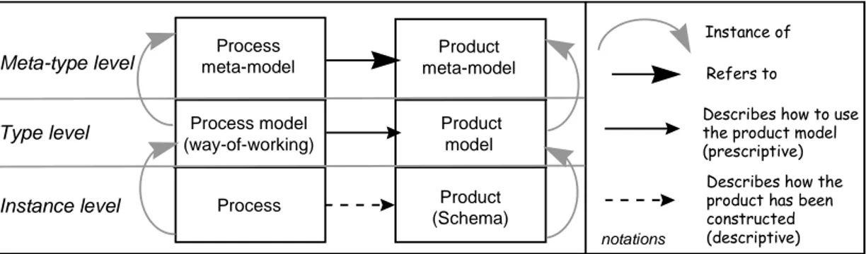
There is still no standard for process abstraction. However, it is possible to contrast it with the IRDS standard and levels of abstraction for processes. As shown in figure 1, a process is an instance of a process model defined at the instance level. For instance, the process records that the goal "Minimise the risk of aircraft crashing" is identified first and then it is decomposed into a set of sub-goals. The underlying process model is described at the type level, it states that decomposing a goal can be performed after the identification of the goal. A process model is an instance of a process meta-model. A process meta-model is defined at the meta-type level. Based on this, the previous example of process model is an instance of a process meta-model allowing a description of concepts that can be identified in sequence.
Putting those examples together highlights the relationships between process and product. The process keeps track of how the product has been constructed in a descriptive manner. Similarly a process model defines how to use the concepts defined within a product model. Finally, a process meta-model refers to the meta-types of the product meta-model.
2.2. Background
A study of the state-of-the-art suggests that existing process models can be classified into three categories [14]: activity-oriented models, product-oriented models, and decision-oriented models. Each category has an underlying paradigm that may be examined in terms of its appropriateness to change process modelling.
2.2.1. Activity-oriented models
Activity-oriented models are dominant in the literature, probably because they advocate an intuitive way of problem solving: establish a plan of actions and apply the actions following the order prescribed in the plan. These models attempt to describe the development process as a set of activities with conditions constraining the order of the activities. The difference between these models relies on the variety of ways that they allow the designer to express the system and the associated languages. Refer to [20] for a comprehensive survey of activity-oriented models.
Activity-oriented models were inspired by generic system development approaches (e.g. the Waterfall model [54], the Spiral model [7], the Fountain model [25], etc.). The underlying paradigm is one of hierarchical decomposition of activities. Initially, the aim of such process models was to define a general framework for system definition and implementation by providing a process description at a very high level of granularity (the different steps of the development and their linking). However, such models can also be used for decomposing macro-activities from a large step into micro-activities of smaller steps. Practically, a large
number of methods have been using this type of model. The OMT method [55], for instance, suggests the following sequence of activities: 1) establish an initial description of the problem, 2) construct an Object Model, 3) construct a Dynamic Model and 4) construct a Functional Model. Each of these activities is decomposed into smaller activities.
The process meta-model corresponding to this class of models is based on the two concepts of activity and activity linking condition.
In addition, these models have often used informal means for process description such as natural language or diagrams with informal semantics. This has made them hard to analyse, to improve or to follow systematically.
The recent emergence of formal software process models (e.g. [3], [20]) is likely to make activity-oriented process models better suit the new goals of process engineering. However, very few modelling approaches rely on "formal foundations"; most define how to operate more or less informally. This new generation of process models remains activity-oriented even though the initial activity decomposition paradigm has been extended in various ways: Petri nets in EPOS [29] and SPADE [4], rule based in MERLIN [18], ALF [6], Marvel [31], EPOS, and triggers in ADELE [5] and MVP-L [20]. It is interesting to notice that formality relates to the underlying programming languages: Smalltalk for E3, various Prolog dialects for EPOS, Oikos [1] and PEACE [20], PS-Algol for PWI [29].
Most of these models were inspired by the programming process introduced in [41] which makes an analogy between computer programs and the development processes : a development process should be described as a program and expressed in one or several languages, similar to programming languages. Once described, the process program (or model) can be enacted. The process model is then used to control the execution of the process from which it is an instance of. Bandinelli et al state that "In a process centred environment, a process plays the role of a
program to be executed in order to control and manage the process". Many activity-oriented
process models are based on this hypothesis in despite of the criticism of [33], which argues that process programming only allows one to represent the well assimilated parts of processes not the creative parts essential to development, for instance in the use of heuristic, the choice of alternatives, back tracking decision, etc..
Activity-oriented process models do not explain how the product is constructed, what the input and output of the activities are, and why activities are performed. The linear view of activity decomposition promoted by this paradigm is inadequate to model the change process, because of all the alternatives that must be considered. Procedural representations cannot incorporate the rationale underlying the process and therefore do not permit reasoning about engineering choices based on existing alternatives. It is unrealistic to plan what will happen in
an entirely sequential manner. Finally, the linear view is also inadequate for ways-of-working which have to support backtracking, reuse of previous designs, and parallel engineering. These are necessary in the context of EKD.
2.2.2. Product-oriented models
The product-oriented process models define the development process through the evolution of the product. They promote a view of a development process which is centred around a development activity but, additionally, link development activities to the product. Furthermore, the conditions for triggering activities are specified over the life of the product. The underlying process meta-model is built on three concepts: product state, activity and state transition.
Product-oriented models do not put forward the activities of a process but rather the result of these activities. They establish an explicit link between the activities and the resulting product. The ViewPoints model [19] and the development process model proposed in the European Software Factory (ESF) project [21] belong to this category. Others product models have been proposed in the literature [37], [59]. We illustrate this class of models with the EPM model [27] which considers development processes as successions of state transitions of product elements called entities. At a given point in time, an entity is in a unique state. For example, a program module can be in the "none" state - the initial state - in the "under development" or "tested and transferred" state - the final state. States are either active, if the entity is currently under transformation - e.g. "under development" - or passive - e.g. "tested and transferred". State transitions are triggered by events, possibly under conditions. A state can be decomposed into sub-states, leading to internal state transitions. Thus, the model includes the meaningful elements of a process model, the product elements, and permits an accurate measure of the level of progress in the process. Analysing the states allows the designer to consider completed entities rather than a vague and partial progress measurement of an activity, such as that suggested by activity-oriented process models. State diagrams are used in the specification and design phases of large and complex event-driven systems which have to continuously interact on internal and external stimuli [24].
A positive aspect of the product-oriented approaches is that they model the evolution of the product and couple the product state to the activities that generate this state. They are useful for tracing the transformations performed and their resulting products. However as far as guidance is concerned, and considering the highly non-deterministic nature of the EKD process, it is probably difficult to write down a realistic state-transition diagram that adequately describes what has to happen during the EKD process.
The most recent class of process models follows a decision-oriented paradigm. The successive transformations of the product are looked upon as consequences of decisions. According to these models, a way-of-working does not only specify the linking of activities or product states but also the intention behind the execution of activities and their linkings.
The process models of the IBIS [43], DAIDA [30], [53] and NATURE [48] projects fall into this category. Such models are semantically more powerful than product-oriented models because they explain not only how the process proceeds but also why transformations happen. The concept of Action or Activity is put in the background while the intention that results in a decision is pushed into the foreground. For example, while constructing an actor model, the creation of the actor "Pilot" becomes secondary, whereas the intention : "we need to represent pilots", becomes predominant. The intentions are often motivated by arguments that strengthen or refute them. In the example, pro and con arguments will be associated with the decision to create the actor "Pilot". The fact that pilots are responsible for the execution of the take off, landing, etc. is a pro argument for this decision.
The IBIS model put the emphasis on decision making and its rationale, the development process is modelled by showing reasons why each decision was made. The purpose is to represent a decision process as a network, essentially composed of issues, positions, and arguments. The IBIS model and its derivatives - the REMAP model [45], the PDS model [13] from the ESPRIT II project MACS and its associated language DRL (Decision Representation Language) [32] - focus on tracing processes, they are descriptive models.
This type of models allows a user to capture more process knowledge than the two other approaches. Decision-oriented models are not only able to explain how but also why the process proceeds. Their enactment should control the performance of actions -as activity and product-oriented models can do-, and also be able to (a) guide the decision making process that shapes the development, (b) help reasoning about the rationale of decisions, and (c) record the associated deliberation process.
2.2.4. Discussion
Putting aside the different expression formalisms, activity and product-oriented models have similar expressiveness capabilities. Though this expressiveness suits the modelling of program development and test processes, it is not sufficient for modelling analysis processes where human reasoning is a major component. The execution of the activities of such processes are the consequence of human decisions. Decision-oriented models allow the user to trace processes, highlighting why decisions were made and thus facilitating the introduction of change in systems requirements.
Thus a decision-oriented modelling paradigm seems to be the most appropriate for the EKD process both for trace and guidance purposes. The addition of a capability to record the design decisions facilitates understanding of the engineer's intention and thus, better reuse of the results. However, EKD processes are not adequately covered in existing decision-oriented models. At any time, an EKD engineer is in a situation that he/she views with some specific
intention. His/her reaction depends on both these factors ; i.e. on the context in which he/she is
placed. He/she reacts contextually, often by analogy with previous situations in which he/she has been involved [48].
3. An overview of the EKD process 3.1. The EKD process is guided
First, we consider any EKD process as a decision making one, i.e. non deterministic. It is
performed by responsible agents having the freedom to decide how to proceed according to their evaluation of their situation. Agents do not necessarily follow a predefined plan of action. Defining and implementing change requires a number of decisions to be made : what to consider in the existing organisation ; what shall be improved ; the alternative solutions ; the selection of the most appropriate solution ; etc..
Secondly, the EKD process cannot be ad-hoc and chaotic. It cannot be only based on
intuition and personnel behaviour of engineers and stakeholders. We look to it as a repeatable process made of steps resulting from the application of a pattern for decision making. The pattern is generic, in the sense that it is applicable to any decision making activity. The proposed EKD way-of-working is entirely based on this pattern.
Third, the pattern views a decision as the choice of the way to proceed in a given situation
to achieve an intention. A decision is contextual ; i.e., both situation and intention driven. The rationale is that, following a decision based approach per se is not enough in our setting. As a matter of fact, the intention to "reorganising the airport in order to increase passenger traffic", may be implemented in different ways, depending on the airport to be reorganised. Indeed, an intention can be fulfilled in different ways depending on the situation being considered. In order to take this aspect into account, we propose to fully associate the intention and the situation in a context.
Definition 1 : A situation is a part of the product it makes sense to make decision on. A
situation can be defined at various levels of granularity, it can be a single element of the product - for example a class in an OMT object model [55] - or a composition of product parts - for example a complete object model representing the Paris-Roissy Airport today.
Definition 2 : An intention expresses what the engineer wants to achieve, it is a goal. An
intention can be strategic or operational allowing various levels of granularity in the decision making process. For instance, a strategic intention can be "define an object model" or "increase passenger traffic" whereas an operational intention can be "add a new attribute to a class" or "add a check-in desk". A strategic intention corresponds to a high level requirement that needs to be further decomposed into more detailed intentions whereas an operational intention can be implemented into a sequence of actions.
Definition 3 : A context is the association of a given situation and an intention that the
EKD engineer wants to achieve in this very situation. We use this concept as the basic building block for describing an EKD process.
In the remaining the paper, the terms "situation", "intention" and "context" will be used with these specific meanings.
Therefore, within EKD, any process element is described as a couple <situation, intention>,
such as:
<The Paris-Roissy Airport today, Operationalise goal "increase passenger traffic">,
<Goal G1: "Maintain separation standards between planes", Find design model satisfying goal G1>, etc..
Thus, any process model is described as a set of context types -situations are described at the type level. We could define context types such as:
<Goal X, Operationalise goal X>,
<Goal Y, Find design model satisfying goal Y>, etc..
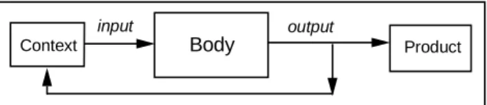
Therefore, if we visualise the decision making pattern (figure 2) as having an input, a body and an output, the input is a couple <situation, intention>, i.e. a context. In some sense the pattern is bounded by the situation and the associated intention. It is close to the notion of context used in Artificial Intelligence [58].
Change engineering requires a complex process to take place. However, there are some steps during the performance of this process that are grounded on knowledge.
First, there is heuristical knowledge that consists of the know-how of EKD engineers. For instance, when trying to operationalise the goal "increase passenger traffic in an airport" in the context of the Roissy airport, he/she may refer to the experience gained during the reorganisation of London’s Heathrow airport and recall that the goal "increase passenger traffic in an airport" was articulated into two complementary sub-goals.
Secondly, an engineer may try to reuse knowledge independent of any particular domain but
specific to EKD. For instance, while classifying a goal, he/she refers to some existing and well
understood categories, the elements guiding his/her selection of the appropriate class are known a priori, they are reused for the classification of every goal. Similarly, the operationalisation of a goal follows some patterns: a goal can be reduced to a set of alternatives or to concomitant goals or it can be expressed through a business rule. This type of knowledge is specific to EKD and can be used in any organisational setting.
Finally, when an engineer has to solve a new design problem, he/she could structure his/her reasoning by looking for alternative ways to solve the problem or by decomposing the problem into smaller problems. This type of knowledge is fully generic and not tailored to EKD.
The body of the decision making pattern provides the knowledge to make the decision. The pattern is intended to provide guidance on how to proceed to achieve the intention in the given situation.
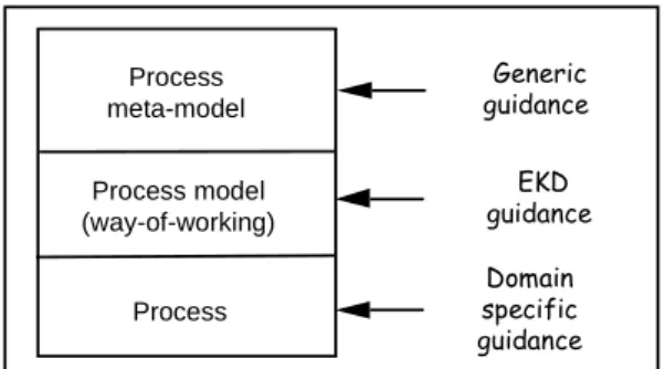
Our approach provides, three types of guidance: generic guidance, EKD guidance and
domain specific guidance. Generic guidance is independent of any specific methodology
supporting decision making; e.g. not specific to EKD. It can be seen as the common set of rules for guiding decision making and is based on generic method knowledge. The rule "proceed in the achievement of a goal by identifying alternative choices that make this goal executable through actions" is an example of generic guidance.
EKD guidance is tailored to the way EKD envisions a change process to occur. Providing a
rule for “classifying a business objective into one of the objective classes : "achieve", "avoid", "cease", "extend" or "maintain"” is specific to EKD. It is based on EKD method knowledge.
Domain specific guidance depends on the application domain. Any guideline related to Air
Traffic Control belongs to this type. It is based on domain specific method knowledge.
As depicted in figure 3, the three types of guidance can be related to the levels of abstraction.
The output of the decision making pattern is of two different types : an action performed on the product being designed or a new situation coupled to an intention. It is the nature of intention that determines the output type.
Intentions such as “Operationalise the goal "increase passenger traffic"” are high level objectives that cannot be immediately implemented through actions in one step of the process. The refinement of the intention might require several steps, each of them contributing to the operationalisation of the goal. The decision making in one of these steps consists of generating a new context, i.e. a couple <situation, intention>. “Operationalise the goal "increase passenger
traffic"” might for example, require “Operationalise "Decrease plane turn-around time"” and therefore, the step having as input the context <Roissy airport today, Operationalise goal "increase passenger traffic"> will have as output the context <Roissy airport plane movement description, Operationalise goal " Decrease plane turn-around time">.
It could also happen that the EKD engineer knows exactly how to “Operationalise goal X”, by reducing the goal into sub-goals X1 and X2, etc.. The decision made by the EKD engineer at this step s1 will consist of an action to replace goal X by a new structure. However, the change in the product raises new situations. For example, step s2 can contribute to the emergence of the two contexts: <Goal X1, Associate design model to X1> and <Goal X2, Operationalise X2>.
3.2. The EKD process is incremental and dynamic
The suggested way-of-working makes the EKD process iterative, each step of the process repeating the EKD decision making pattern. As a consequence, the product (i.e., the new business processes of the company) is incrementally constructed. This suggests a spiral representation of the process. In addition, the sequencing of steps is not fixed. Steps
dynamically follow one another. This is brought about by the decision making pattern, which
does not impose any predefined sequence of the decision making process but allows EKD engineers to switch from one context to another, depending on new situations and changes.
3.3. The EKD process is supported by software tools
Both the information system and the software community have automated their methods and now use tools. So is the EKD approach. The support provided by the EKD tool environment comprises three aspects (1) guidance based on the EKD way-of-working; (2) trace of the EKD process; and (3) backtracking and replay facilities. The generic tool MENTOR (co-developed by one of the authors) supports the three aspects [57]. It is currently being customised to EKD.
3.3.1. Automated guidance support
The EKD environment provides guidance in the performance of the process by using the Dowson's framework [15] (figure 4). The framework introduces three interacting domains: process
modelling, process performance, and process enactment.
Process modelling captures all activities performed for modelling the software development
processes: process model definition, process model specialisation, etc.. Process enactment encompasses what takes place in a process to support process performance, based on the process definitions. This is essentially an interpretation of an instantiated process model that
guides, enforces, or partly automates process performance. The relationship between the process modelling and the process enactment domains is the instantiation of the process model.
Process performance involves the set of activities conducted by human and non-human agents
(e.g., the computer). The relationship between the process performance and the process enactment domains is twofold : (1) support, control, and monitoring of activities of the process performance domain, and (2) the feedback performance for process adjustment.
The process model supporting the EKD way-of-working comprises three classes of process model fragments : generic method chunks ; EKD method chunks ; and domain specific method
chunks. All chunks are stored in the repository of the EKD environment and accessible at any
time.
3.3.2. Tracing support
Empirical studies [35] have shown that analysts and developers know very little about the process they go through. Process traceability is therefore an important issue in design. It can be divided into three parts: process execution, product evolution, and their relationships. Traceability has many uses in the design process, especially in the early phases of development where the requirements for the system are elicited and defined [42].
Within EKD, the trace comprises both process and product aspects. The process trace itself keeps track of the application of the decision making pattern at each step. The step by step evolution of the product are stored as versions of the product, thus providing configuration management material. The relationship between the product and the process traces allows us to relate decisions to their effects on the product.
3.3.3. Backtracking and replay support
Backtracking to a previous step in the process may help by replaying the process in a different way. Replay is often necessary to support changes occurring during the process itself or later. Replay is another form of process enactment which is made possible by the enactment mechanism of the EKD tool.
4. Guiding the EKD process
This section deals with the brief presentation of the process meta-model (see [39], [40] and [52] for a detailed presentation) underlying the decision making pattern and the way it provides guidance.
The EKD decision making pattern is a reasoning mechanism supporting decision making by providing a set of predefined concepts, a library of guidelines and a set of predefined rules (see figure 5). The concepts identify the elements supporting the reasoning. The rules play a dual role. First, they help in the retrieval of the appropriated guidelines from the library. Second, rules are used to guide the decision making according to the guideline. Input and output of the rules are contexts.
The pattern can be compared to an expert system matching facts (the input context) to fact types (the guidelines) in order to generate new facts (the output contexts). The rules of the decision making pattern play a role similar to the inference engine of an expert system. When the EKD process is under the control of the tool environment, the matching activity is automated, whereas an EKD engineer working manually must remember or look up rules by hand.
4.2. Concepts underlying the EKD decision making pattern: an overview of the process meta-model
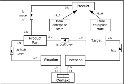
Figure 6 depicts the core elements of the EKD process meta-model. As defined in section 3.1, a context tightly couples a situation to an intention. A context corresponds to one step of the EKD process. A situation is built from an EKD product part and sets the product elements considered during one step of the process. An intention expresses the goal the EKD engineer has in mind, it has a target describing what should be the result of the decision made in this context. Similarly, a target is built from EKD product parts. Both situation, target and intention can be described at different levels of granularity from coarse to fine grain.
4.3. Generic guidance
4.3.1. Using the generic guidance
The method repository has only one generic guideline : the generic method chunk or
generic chunk.
The chunk is applicable in situations where the two other types of guidelines do not hold ;
i.e. when there is no domain specific guideline available, nor EKD guideline meeting the current situation and intention. The guideline aims to fulfil the "help me" request. It proposes an help strategy for progressing in the EKD process that offers three options: do, plan, and
choose. Each will correspond to a given type of context : executable, plan and choice context,
respectively. Accordingly, the generic chunk provides three options:
• do, which corresponds to a straightforward resolution strategy. It is chosen when the
engineer knows exactly what needs to be done in order to fulfil the intention of the context. The EKD engineer is required to specify the design action(s) and their effects on the design product. We call this type of context executable.
• choose, which corresponds to a resolution strategy that requires the exploration of
alternative paths. It is selected when the engineer thinks about different alternatives but has not make up his/her mind about the one to select. The engineer shall specify all possible alternatives and elaborate an argumentation for each of them. Based on the proposed arguments, the enactment leads to the selection of an alternative path that seems most appropriate. This is termed a choice context.
• plan, which follows a planning strategy. The engineer already has a plan for achieving the
intention. In this case, following a divide and conquer tactics, the EKD engineer will progress by building a plan consisting of decisions to be made. This is called a plan context.
Note that the two last options correspond to the classical reduction operator in the problem
reduction approach to problem solving [38].
Working with the do strategy means that the EKD engineer is able to specify the actions that operationalise the process goal and to execute them immediately. One should notice that the process is constructed dynamically, the generic chunk helping in identifying the case in hand (the do strategy) and providing the procedure to be followed (specifying actions and their impact on the product).
The plan context corresponds to a well-known approach in strategic decision making : state a plan and then execute the plan [61]. Again, this is dynamic. The EKD engineer working in a plan context will state the components of the plan he/she has in mind as new contexts and will enact them immediately.
4.3.2. Revising the process meta-model
While presenting the use of generic knowledge we refined the notion of context by defining three types of context : executable, choice, and plan. These are generic properties of contexts that we introduce in the meta-model. Figure 7 summarises the different concepts completing the first version of the process meta-model.
The different types of contexts are modelled as sub-types of the concept of context and therefore share the same structure <situation, decision>. The different components (respectively alternatives) of a plan context (respectively choice context) are contexts too. This provides the means of constructing hierarchies of contexts that are needed to represent complex decision based processes.
There are some major differences between the various types of contexts. There is no alternative in an executable context. The execution of a choice context has no direct
consequence on the product under development. A choice context allows progress in the change process by refining the intention whereas an executable context directly implement the intention. Plan contexts provide a different type of progress. They help in decomposing a high level intention into sub-intentions and therefore simplify the given context by decomposing it.
It may be argue that this process meta-model is too complex. However, one principle at the core of several machine learning system [60] is : "The more knowledge at the meta level, the
more knowledge based guidance can be provided to acquire requirements fragments at the domain level."
4.3.3. Extending the decision making pattern for supporting co-operative work processes
Parts of the EKD process are dealing with ill-defined problems for which even the generic guidance provided by the decision making pattern might be found to be too inflexible. The elicitation of goals is an example. Setting the opportunities, weaknesses, threats and strengths for a change process is another. As pinpointed in [2] and [12], finding goals is very hard and there is not yet a way of solving this problem efficiently. Organising co-operative work sessions and brainstorming are probably the best approaches to deal with this kind of highly creative activity. The problem is therefore, to be able within the EKD way-of-working, to support both ill-structured and well (or better)-structured procedures.
However, the decision making pattern proposes different types of guidance that could be too inflexible. These observations leads us to extend the decision making pattern in order to support also the creative part of work processes.
4.3.4. Extending the process meta-model
Since there are a number of participating users in ill-structured co-operative activities, there is a need to have a way to represent conversations in the process meta-model. Additionally, it is necessary to explicitly bring the notion of a role to the process meta-model.
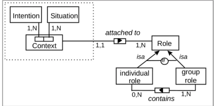
4.3.4.1. The concept of role
In the EKD approach, we are dealing with co-operative design processes. Acting within a context corresponds to a step in the co-operative process to which various stakeholders participate with well defined roles: in a given situation, the EKD engineer has an intention, and that makes him/her enter into a co-operative process.
A role is the definition of the needs shared by the collection of users, all of whom have the same privileges and obligations to a set of work processes in an organisation. We introduce the
concept of role, and then, specialise it into individual role and group role (figure 8). Each context is attached to a role.
In the ATC case study, examples of roles are as follows: - Airport manager (individual role)
- ATC centre manager (individual role)
- Risk elucidation group (group role containing the airport manager, the ATC manager, and other individual roles)
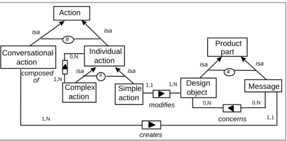
4.3.4.2. Specialisation of the action and product concepts
We are dealing with group activities, in the sense that several participants can synchronously act together by exchanging messages. In the context of the EKD process, we represent ill-structured and highly creative co-operative work sessions by using the
conversation concept and introduce a conversational action. This leads us to classify actions
into two types : individual and conversational.
Performing an action changes the product and may generate a new situation which is itself, subject to new intentions. Individual actions perform transformations of design objects while conversational actions create messages. In order to take account for this distinction, we classify the concept of product into design object and message (figure 9).
We must represent conversational activities during the EKD process and keep track of the conversations. We introduce the message concept as the basic component of the conversational activity. A message may deal with several design objects.
The conversational action is performed by a group role. It creates several messages, each being produced by an individual role contained by the previous group role.
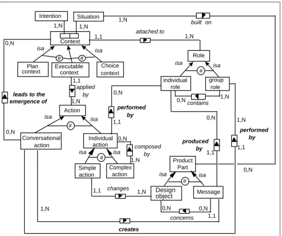
From any conversational action may emerge new contexts (figure 10). These can be executable and associated with actions that might be conversational and then trigger new contexts and so on.
We propose a further refinement of the concept of message based on works on Design rationale [10], etc. The refinement introduces a classification of messages into expression,
argumentation and position (figure 11). An expression can suggest argumentations. These can
support several positions. Finally, an expression can be suggested by any position.
4.3.5. Extending the generic guidance
We extend the generic method chunk in order also to provide co-operative activities. Indeed, the three previous options (do, choose, plan) must have a fourth option : brainstorm. This is supported by an argument "the current situation requires co-operative brainstorming". The associated alternative is an executable context <Input context, Use the brainstorm strategy,
EKD engineer>.
4.3.6. Illustrating the conversational action
We use an example from Air Traffic Control as a case study. Consider the context C: <(G1 "minimise risks of accidents", Operationalise G1), Help me> attached to EKD engineer. Assume the EKD engineer does not know how to proceed and none of the three choices offered by the generic chunk is appropriate. In this case, he/she shall consider the option of calling a group of experts (we name it the "risk elucidation group") for a brainstorming session.
Thus, the strategy needed for context C in the generic chunk is "brainstorm". The guidance provided by this strategy suggests the following tactics:
(1) define the group role required,
(2) execute a conversational action within the previously defined group role with the initial input context as its situation.
The Risk elucidation group may be a role that contains stakeholders such as airport manager, ATC centre manager, a representative of airlines managers, a representative of pilots, and a local authority.
The executable context is applied by a conversational action leading to the creation of several messages (figure 12).
Possibly the flow of messages is:
Message 1: (ATC centre manager)
Have we got a report about reasons of world-wide accidents in the last five years ?
Message 2: (Airport manager)
No, we don't. But we have some information about the last three major accidents.
Message 3: (ATC centre manager)
So, what were the reasons ?
Message 4: (Airport manager)
In Strasbourg, France, it was a human error.
At Delhi, it was due to two factors : heavy air traffic and human error. Due to his poor knowledge of the English language, the pilot misunderstood the message of the control tower.
In the US, it was a confusion about the airport. The pilot made an error in ‘typing’ the airport and the computer understood the airport code as Bogota in South America, while the aircraft was to land in California.
So if we want to minimise risks of accidents we have to decrease risk of human error.
Message 6: (Pilots representative )
Sometimes what is called human error is not really that. How can you decrease the human error in the accident in the US. You must consider computer systems errors.
Message 7: (ATC centre manager)
It's more convenient to talk about Human-Computer interface for this accident. So, our goals are to decrease risk of human error and review all human-computer
interactions.
Message 8: (Pilots representative)
And what about the accident in Delhi ? The human error was not the unique reason, was it ?
Message 9: (ATC centre manager)
The number of aircraft allowed to cross the controlled airspace is too high in Delhi.
Message 10: (Local authority)
Precisely, for 2 years local authorities have been arguing that this number must be decreased here too. People living near the airport are disturbed because of the noise especially during late/early take offs and landings. In order to minimise risks of
accidents we must limit the number of aircraft allowed to cross the controlled airspace. As a conclusion of this message exchange, the conversational action generates three contexts as follows:
- < Message 5, Create G2 : "decrease risk of human error"> - < Message 7, Create G3 :"review human-computer interactions">
- < Message 10, Create G4 :"limit the number of aircraft allowed to cross the controlled airspace">. The new contexts are inserted in the contexts pile for further processing.
4.3.7. Formalising the generic method chunk
We advocate a formal representation of the generic chunk based on the process meta-model. Figure 13 visualises the generic chunk as a choice context using our graphical notations. The four strategies are the four alternative choices proposed by the context together with their related arguments. The guidance provided by the generic chunk can be simply summarised by four questions to the EKD engineer :
- Is your intention operationalisable through design actions? - Can you set alternative ways for fulfilling your intention?
- Do you need a plan for making up your mind and achieving your intention? - Do you need a co-operative work session for fulfilling your intention?
The alternative contexts are executable; their associated actions guide the EKD engineer in performing things according to the option he/she chooses.
Our proposal is for a representation of all method chunks (generic, EKD dependent or domain dependent) in the EKD method base using the concepts of the process meta-model.
4.4. EKD guidance
EKD guidance is based on EKD knowledge. Thus knowledge is needed for supporting EKD
engineers in specifically undertaking the change process in an organisation using the EKD models. Using this knowledge allows us to speed up EKD processes because it concentrates on the resolution of EKD specific problems.
4.4.1. Modelling EKD Knowledge
EKD knowledge supports the construction of different models representing the initial (the initial product) as well as the future state of the organisation (the design product), the expression of alternative strategies for change, as well as the evaluation of these strategies, and other kinds of activity, such as brainstorming, co-operative work, etc..
We express this knowledge by using the process meta-model and the different types of context : executable, plan, and choice. However there is one major difference: the EKD knowledge is expressed at the type level ; i.e., the level of specific classes of EKD phenomena such as "identifying goals", "operationalising goals", "finding design models meeting specific goals", etc.. The type level is distinct from the instance level where one speaks of a specific goal or of a specific design model. It has also, to be differentiated from the meta-level dealing with generic concepts, such as 'product part' and 'intention'. The generic knowledge is at the meta-level whereas the EKD knowledge is at the type level.
More generally, the EKD knowledge can be re-used for decision based guidance in many different participative design processes within different companies.
4.4.2. Using EKD guidance
The way EKD knowledge is used within the EKD decision making pattern is similar that for the generic guidance. The main difference lies in the retrieval of the method chunk. The retrieval of an EKD method chunk is based on matching: assuming that the engineer has chosen the input context, he/she must select an EKD method chunk where (1) the situation type matches the situation of the input context and (2) the intention of the method chunk matches that of the input context. Of course, this selection is greatly facilitated by the use of a software tool.
The remaining part of the reasoning loop associated with the application of the EKD decision making pattern is similar to that previously discussed, but the EKD engineer is more
guided.
We use a matrix presentation to overview the collection of chunks included in the EKD knowledge base. The chunks are the matrix elements. The columns of the matrix are intentions that arise during the EKD process. The rows of the matrix are techniques. The same technique can be used in different ways for different chunks. For example, a brainstorming strategy may be used for both satisfying the intention of "Detect goal conflict" and for "Solve goal conflict".
The essential benefit the EKD engineer gains is in its guidance. By following the heuristical knowledge embedded in the method chunk, the engineer is constantly aided. Part of the solution he/she has to find is provided by the chunk. Suggestions are made on the alternative strategies, predefined plans, etc..
4.5. Domain specific guidance
EKD domain specific guidance is based on EKD domain specific knowledge. The domain specific knowledge aims at providing guidance for solving very well focused problems in a
specific domain. It is grounded on experience based knowledge and suggests reuse and adaptation of previously tested solutions. The benefits of using this type of knowledge is that it considerably shortens the decision process.
4.5.1. Modelling domain specific knowledge
In the context of Air Traffic Control, domain specific knowledge could suggest that the operationalisation of the goal G1: "Minimise risk of crashes" can be achieved in two ways : a decomposition of G1 into G2: "Maintain separation standards" and G3: "Decrease risk of human error" or a decomposition with G3 and G4: "Limit the number of aircrafts allowed to cross a controlled airspace".
4.5.2. Using domain specific guidance
The use of domain specific knowledge within the EKD decision making pattern is relatively unchanged from before. The difference lies in the fact that domain specific method chunks are defined at the instance level and therefore do not have to be instantiated when used.
5. Global view of the EKD process 5.1. An incremental design process
We view the EKD process as consisting of the iterative application of the decision making pattern. This leads to an incremental production of the EKD product ; i.e., of the various
models suggested in our approach. Consider a synthetic view of the key parts of the EKD set of models as depicted in figure 14.
- the Enterprise Model provides a view of the current situation, its goals, problems, actors, activities and concepts;
- the Goal Model represents the objectives for the new system; - the Design Model represents the solutions to meet the objectives;
- Scenarios help in the validation of the solutions, particularly in illustrating how a given design model achieves the goals.
The incremental dimension of the process means that the Enterprise Model does not need to be completed before some goals for change are stated and even associated with some design model. In terms of decision making, it means that decisions are not made in a linear fashion. We can then split the process into :
- Model the current enterprise state - Acquire goals
- Operationalise goals - Generate design models - Validate design models
In order to illustrate the non linearity of the process, consider two sequences in figure 15. As used in other approaches [7], [8], we propose a spiral representation. As illustrated in figure 16, the angular dimension shows the degree of completeness achieved by the current process. The radial dimension shows the progress that has been achieved and might be associated to a measure of the effort spent in the process.
Obviously, there is a logical order to be followed for some decisions. For example an "operationalisation" decision cannot be made if the corresponding "acquiring" decision has not be made. But it will be a constraining to force ; for example, all "acquiring" typed decisions to be made before any "operationalisation" decision.
Taking into account the ordering constraint between the five types of decision (Model - Acquire - Operationalise - Generate - Validate), the EKD process results in a hierarchy of spirals, as shown in figure 17. The hierarchy of plans reflects the logical ordering. Every turn of spiral in a plan might have several turns in the descendant plan which represent the succeeding steps of decisions of a type X performed as sons of the same father decision of type Y. The hierarchy of plans models the ordering constraint, the spiral movement means a relaxed completeness constraint on decisions made.
Another interesting feature of the EKD process is its dynamic nature. The flow of decisions is not defined "a priori" but constructed dynamically. Therefore, the EKD engineer can switch from context to context depending on the changes. The output of one application of the pattern is one or more contexts that associate an intention to the situation in which it must be achieved.
The number of possible contexts that can be selected at a particular step s may be more than two. In fact, there is a pile of pending contexts. The pile represents the set of decisions that have to be made for the process to be completed. The pile is originally empty, grows in the beginning of the process as it proceeds and progressively reduces to an empty set at the end. Roughly speaking the process pushes and pulls decisions (in their contexts) from the pile. Each step makes a decision and may generate new decisions.
The selection of one context in the pile at a given point of time t is free. It is a choice that is offered to the involved stakeholders. They are free to proceed from step to step according to their view of the contexts to be pulled from the pile. Some guidance may be provided to help the EKD engineer making the choice. A situation matching mechanism is one example, a query language is another. The matching mechanism allows the user to select contexts in the pile that match existing EKD or Domain dependent chunks. Using the query language, the EKD engineer is able to select those contexts which match the current needs.
6. Conclusion
The EKD decision making pattern is a reasoning mechanism supporting decision making by providing a set of predefined concepts, a library of guidelines and a set of predefined rules. First, rules help in the retrieval of the appropriated guideline from the library supporting decision making at that particular stage of the process ; i.e. in the current situation at hand. Secondly, rules are used to guide the decision making according to the guidelines.
The decision making pattern is tailored to provide guidance for all cases. In some cases, the pattern offers domain specific guidance. This happens when the library contains knowledge about the domain of the project that matches the current context.
The library also contains EKD specific guidelines that describe how to work with different EKD models following the EKD approach. These guidelines are independent of any particular domain but are based on EKD Method Knowledge.
Finally, if none of the two types of guidelines matches the current context of work, the generic guideline may operate ; it is the default option in some sense. Clearly, making guidance more specific increases its efficiency. However, the generic guideline allows the EKD process to be entirely based on guidance.
We can view the reasoning mechanism offered by the decision making pattern as consisting of two main steps: selecting the relevant guideline from the library for the current situation and intention and then making a decision according to the guideline. Currently, we are implementing these guidelines in an electronic handbook which will eventually be made available on the World Wide Web.
References
[1] V. Ambriola and M.L. Jaccheri, Definition and Enactment of Oikos software entities, in: Proceedings
of the First European Workshop on Software Process Modelling, Milan, Italy, 1991.
[2] A. Anton, Goal-Based Requirements Analysis, ICRE '96, IEEE, Colorado Springs, Colorado USA, (1996).
[3] P. Armenise, S. Bandinelli, C. Ghezzi and A. Morzenti, A survey and assessment of software process representation formalisms, International Journal of Software Engineering and Knowledge
Engineering, 3(3) (1993).
[4] S. Bandinelli, A. Fugetta and S. Grigoli, Process Modelling in the large with SLANG, in: Proceedings
of the 2nd International Conference on Software Process, Berlin, Germany, (1993) 75-93.
[5] N. Belkhatir and W.L. Melo, Supporting Software Development Processes in Adele2, Computer
Journal, 37(7), (1994) 621-628.
[6] K. Benali, N. Boudjlida, F. Charoy, J. C. Derniame, C. Godart, Ph. Griffiths, V. Gruhn, P. Jamart, D. Oldfield and F. Oquendo, Presentation of the ALF project, in: Proceedings of the International
Conference on System Development Environments and Factories (1989).
[7] B. Boehm, A Spiral Model of Software Development and Enhancement, IEEE Computer 21(5), 1988. [8] J. Bubenko, C. Rolland, P. Loucopoulos and V. DeAntonellis, Facilitating "Fuzzy to Formal"
Requirements Modelling, in: Proceedings of the IEEE First International Conference on
Requirements Engineering, ICRE'94 (1994) 154-158.
[9] J. A. Bubenko jr., J. Stirna, D. Brash, EKD User Guide, Dpt. Of Computer and Systems Sciences, Royal Institute of Technology, Stockholm, Sweden, 1997.
[10] E.J. Conklin and M. Begeman, gIBIS: A Hypertext Tool for Exploratory Policy Discussion, ACM
Transactions on Office Information Systems, 6(4) (1988) 303-331.
[11] B. Curtis, M. Kellner, J. Over, Process Modelling, Communications of ACM, 35(9) (1992) 75-90. [12] A. Dardenne, A.v. Lamsweerde and S. Fickas, Goal-directed Requirements Acquisition, Science of
Computer Programming, Vol. 20 (1993) 3-50.
[13] C. Desclaux, A. Guthauser, T. Pécoud, J. Pomian, P. Storr and A. Thierry, Design & Maintenance Process Rationale under MACS, Conférence Le génie logiciel et ses applications, Toulouse, France (1990).
[14] M. Dowson, Iteration in the Software Process, in: Proceedings of the 9th International Conference
[15] M. Dowson, Consistency Maintenance in Process Sensitive Environments, in: Proceedings of the
Process Sensitive SEE Architecture Workshop, Boulder, CO (1992).
[16] M. Dowson and C. Fernstrom, Towards requirements for Enactment Mechanisms, in: Proceedings of
the European Workshop on Software Process Technology (1994).
[17] ELectrical Enterprise Knowledge for TRansforming Applications, The ELEKTRA Project Programme, ELEKTRA consortium (1996).
[18] W. Emmerich, G. Junkermann and W. Schafer, MERLIN: Knowledge-based process modelling, in:
Proceedings of the First European Workshop on Software Process Modelling, Milan, Italy, 1991.
[19] A. Finkelstein, J. Kramer and M. Goedicke, ViewPoint Oriented Software Development, in:
Proceedings of the Conference "Le Génie Logiciel et ses Applications", Toulouse (1990) 337-351.
[20] A. Finkelstein, J. Kramer and B. Nuseibeh (eds), Software Process Modelling and Technology, (John Wiley Pub., 1994).
[21] M. Franckson and C. Peugeot, Specification of the Object and Process Modelling Language, ESF Report n° D122-OPML-1. 0, 1991.
[22] F3 Consortium, The F3 Hand Book, SISU, Box 1250, S-164 40, Kista, Sweden (1993).
[23] O. Gotel, A. Finkelstein, An Analysis of the Requirements Traceability Problem, in: Proceedings of
the First IEEE International Conference ICRE'94, Colorado Springs, USA (1996).
[24] D. Harel, On visual formalism, Communication of ACM, Vol 31, N° 5, May 1988, pp 514 - 530. [25] B. Henderson-Sellers and J.M. Edwards, The Object-oriented Systems Life-Cycle, Communications
of the ACM, September (1990).
[26] A.H.M. Hofstede, T.F Verhoef, G.M. Wijers and S. Brikkemper, The SOCRATES project, in:
Proceedings of NGCT'90 , Noordwijkerhout, The Netherlands, April 1990.
[27] W.S. Humphrey, Managing the Software Process, (Addison-Wesley, 1989).
[28] Information Technology - Information Resource Dictionary System (IRDS) - Framework, ISO/IEC International Standard, 1990.
[29] L. Jacherri, J.O. Larseon and R. Conradi, Software Process Modelling and Evolution in EPOS, in:
Proceedings of the 4th International Conference on Software Engineering and Knowledge Engineering (SEKE'92), Capri, Italy (1992).
[30] M. Jarke, J. Mylopoulos, J.W. Schmidt and Y. Vassiliou, DAIDA - An Environment for Evolving Information Systems, ACM Transactions on Information Systems, 10(1) (1992).
[31] G.E. Kaiser, N.S. Barghouti, P.H. Feiler and R.W. Schwanke, Database Support for Knowledge-Based Engineering Environments, IEEE Expert, 3(2) (1988) 18-32.
[32] J. Lee, Extending the Potts and Bruns Model for Recording Design Rationale, in: Proceedings of the
IEEE 13th International Conference on Software Engineering, Austin, Texas, May 1991.
[33] M.M. Lehman, Process Models, Process Programs, Programming Support, in: Proceedings of the 9th
International Conference on Software Engineering, (1987).
[34] J. Lonchamp, A structured Conceptual and Terminological Framework for Software Process Engineering, in: Proceedings of the International Conference on Software Process (1993).
[35] M. Lubars, C. Potts and C. Richter, A Review of the State of the Practice in Requirements Modelling, in: Proceedings of the International Symposium on Requirements Engineering (1993). [36] P. Marttiin, Methodology Engineering in CASE shells: Design Issue and current Practice, PhD
thesis, Computer science and information systems reports, Technical report TR-4, 1994.
[37] M. Nadin, M. Novak, MIND: A Design Machine, Conceptual Framework, Intelligent CAD Systems I (Springer Verlag, 1987).
[38] N. Nilsson, Problem Solving Method in Artificial Intelligence, (McGraw Hill, 1971).
[39] S. Nurcan, C. Gnaho and C. Rolland, Defining Ways-of-Working for Cooperative Work Processes, in: Proceedings of the First International Conference on Practical Aspects of Knowledge
Management (PAKM) Workshop on Adaptive Workflow, Basel, Switzerland, October 1996.
[40] S. Nurcan and C. Rolland, Meta-modelling for co-operative processes, in: Proceedings of the 7th
European-Japanese Conference on Information Modelling and Knowledge Bases, Toulouse, France,
May 1997.
[41] L. Osterweil, Software processes are software too, in: Proceedings of the 9th International
Conference on Software Engineering, IEEE Computer Society, Washington, DC (1987) 2-13.
[42] K. Pohl and S. Jacobs, Concurrent Engineering: Enabling Traceability and Mutual Understanding,
International Journal on Concurrent Engineering 2 (1994), 279-290.
[43] C. Potts, A Generic Model for Representing Design Methods, in: Proceedings of the 11th
International Conference on Software Engineering (1989).
[44] B. Ramesh, A Model of Requirements Tracebility for Systems Development, Tech. report, Naval Postgraduate School, Monterey, CA, September 1993.
[45] B. Ramesh and V. Dhar, Supporting Systems Development by Capturing Deliberations During Requirements Engineering, IEEE Transactions on Software Engineering, 18( 6) (1992).
[46] C. Rolland, Understanding and Guiding Requirements Engineering Processes, invited talk, IFIP
World Congress, Camberra, Australie, 1996.
[47] C. Rolland, Modelling the Requirements Engineering Process, Information Modelling and