HAL Id: hal-02422682
https://hal.archives-ouvertes.fr/hal-02422682
Submitted on 6 Jan 2021
HAL is a multi-disciplinary open access
archive for the deposit and dissemination of
sci-entific research documents, whether they are
pub-lished or not. The documents may come from
teaching and research institutions in France or
abroad, or from public or private research centers.
L’archive ouverte pluridisciplinaire HAL, est
destinée au dépôt et à la diffusion de documents
scientifiques de niveau recherche, publiés ou non,
émanant des établissements d’enseignement et de
recherche français ou étrangers, des laboratoires
publics ou privés.
lithography: fabrication and wetting properties
Céline Cohen, Thierry Darmanin, Jordan Priam, Frédéric Guittard, Xavier
Noblin
To cite this version:
Céline Cohen, Thierry Darmanin, Jordan Priam, Frédéric Guittard, Xavier Noblin. Hybrid surfaces
combining electropolymerization and lithography: fabrication and wetting properties. Soft Matter,
Royal Society of Chemistry, 2019, 15 (45), pp.9352-9358. �10.1039/c9sm01402k�. �hal-02422682�
Soft Matter
ARTICLE
Received 00th January 20xx, Accepted 00th January 20xx DOI: 10.1039/x0xx00000x
Hybrid surfaces combining electropolymerization and lithography:
fabrication and wetting properties.
Céline Cohena, Thierry Darmaninb, Jordan Priama, Frédéric Guittardb, Xavier Noblina,*
We present here first a novel fabrication method in order to obtain hybrid surfaces consisting of mixed hydrophilic/superhydrophobic properties. These surfaces consist in a regular array of hydrophilic pillars (receding contact angle lower than 90°) surrounded by a superhydrophobic thinner layer made by electropolymerization of a fluorinated monomer. Then we present the wetting properties of such complex surfaces by determining the advancing (𝜃𝑎) and receding
(𝜃𝑟) contact angles as function of the surface properties. Two main parameters were varied: the pillar density (spacing d,
from 25 to 45 micrometers corresponding to surface fraction from 21.2 % to 6.5 %) along with the polymer charge (from 0 to 100 mC/cm2). Here, we show that for low charges, only the ground surface is covered by hydrophobic polymers. For
higher charges values, polymerization reaches higher levels on the lateral surfaces of the non-conductive cylindrical pillars eventually up to their top surfaces and covering them for the highest charges. This feature gives an additional parameter for the control of such surfaces wettability. We show that contact angles (advancing and receding) increase strongly with increased polymer charge above a critical charge value (that is higher for receding angles). We also measure that advancing and receding contact angle respectively increase and decrease with increasing pillar density. We interpret qualitatively these behaviors, the main point being how important is the impalement (null, partial or total).
Introduction
For almost two decades, superhydrophobic surfaces has been developed, inspired by nature [1], [2]. A large variety of fabrication methods has been used [3-5], finding numerous scientific [6-14] and technological applications [15,16]. The basic feature shared by most of these surfaces (that present contact angle with water higher than 150°) is the addition of physical roughness to the chemical nature, yet hydrophobic, of the surface. Such surfaces present high contact angle but their contact angle hysteresis (difference between advancing and receding contact angles: 𝑯 = 𝜽𝒂− 𝜽𝒓) strongly depends on the
micro and nano structures of the surface. Two different states have been shown in literature [17]. For low surface roughness, liquid droplets fully penetrate into solid asperities (“Wenzel state”) and then exhibits smaller contact angle and high hysteresis of contact angle [18]. For high surface roughness, air pockets can be trapped between the surface asperities which reduces the real contact areas because drops stand on the top of rough edges (“Cassie-Baxter state”) [19], The contact angle hysteresis is then lower. Three states of roughness can help to classify such surfaces and define the wetting states [20].
In most studies, although rough, the surface treatment at small scales is homogeneous. More recently, hybrid
(hydrophilic/hydrophobic) surfaces have been developed. Main realizations found in literature concern smooth surfaces and dual hydrophobic/hydrophilic properties are obtained either by UV patterning methods or by micro contact printing [21, 22]. Only few studies address mixed wetting properties of the texture itself [23-26]. In this last study, authors have made transparent surfaces composed of array of functional Janus micro pillars with hydrophobic rims and hydrophilic top. The bottom of the surface is also hydrophilic. In [24], authors have taken the advantage of Cassie-Baxter state of droplet to cover hydrophobic microstructures apexes with hydrophilic adsorbed polymers or colloidal particles contained in a droplet deposited on microstructures. This compelling method can limit the size of surface produced because of practical difficulties to create large puddles of water on superhydrophobic surfaces.
The originality of the present work lies in the fact that we can tune the wettability of the surface combining lithography (with deposition of non-conductive pillars on a smooth and conductive substrate) with electropolymerization, to induce the polymer growth from the base substrate. With this method, we can prepare surfaces presenting both superhydrophobic and hydrophilic zones. Using a fluorinated monomer, the bottom surface between pillars is made superhydrophobic. Different situations can be obtained for pillar lateral surface depending on the electrodeposition parameters. Indeed, pillars can be either completely hydrophilic or they can be partly superhydrophobic at their bottom and hydrophilic above a given height (more precisely, the receding contact angle on the pillar material is lower than 90°, as the advancing one is higher than this value). The height of pillar surface covered by superhydrophobic polymers is controlled with the electropolymerization parameters. Indeed, depending on the monomer used and electrochemical parameters, the
a.Université Nice Côte d’Azur, CNRS-UMR 7010 Institut de Physique de Nice, Av.
Joseph Vallot, 06100 NICE, France.
b.Université Nice Côte d’Azur, NICE-Lab, 61-63 av. S. Veil, 06200 Nice, France.
† Footnotes relating to the title and/or authors should appear here.
Electronic Supplementary Information (ESI) available: [details of any supplementary information available should be included here]. See DOI: 10.1039/x0xx00000x
ARTICLE Journal Name
2 | J. Name., 2012, 00, 1-3 This journal is © The Royal Society of Chemistry 20xx
electropolymerization technique allows the deposition of conducting polymer films with various morphology and wetting properties [27]. Here, the deposition charge (𝑸𝑺 in mC/m²) has
been varied to control the amount of deposited polymer. We show for the first time that using an appropriate monomer inducing a three-dimensional growth, the polymerization is first induced on the conductive area but the polymer can also grow on the non-conductive pillars if the deposition charge is sufficiently important. As a consequence, the state of wetting of the pillars, which are also hybrid, can be modified. These complex textured surfaces can allow envisioning new applications [24].
In the first part (materials and methods) we present the fabrication and characterization methods. In a second part (results and discussion) we detail the morphological characteristics of the surfaces and their wetting properties before discussing the results.
Materials and methods
In order to produce the mixed wettability surfaces with hydrophobic bottom and hydrophilic top, ITO (Indium Tin Oxide) surfaces have been covered with hydrophilic polymeric micro-pillars and then with fluorinated polymer films on the bottom between the pillars.
Elaboration of transparent micro-pillars surfaces with non-conducting pillars.
Figure 1. Scheme of the fabrication steps. a) Pillars fabrication. b) Electrodeposition. c) Various heights reached by hydrophobic parts as function of the charge. d) Monomer used for the electropolymerization.
The micro-pillars arrays (Figure 1.a)) were fabricated using classic photolithography with SU-8 photoresist (SU-8 2025 and SU-8 2075, Microchem, Newton, MA, USA). The good adhesion
of the photoresist is ensured by oxygen plasma treatment of the ITO surface before resin deposition by spin-coating. Then, by UV exposure through a mask, square arrays of cylinders (with diameter of 13 µm and spacing between cylinders from: 25 to 45 µm), were fabricated over 5 x 5 cm areas on ITO surfaces. The cylinder height is 15 µm, given by the thickness of the SU-8 layer deposited. The ITO surface is by nature conductive contrary to the polymeric micro-pillars and so the electropolymerization is first induced from this zone. (Figure
1.a)).
Electropolymerization.
The monomer used for the electropolymerization was synthesized using a procedure reported in the literature [28]. The monomer, a fluorinated derivative of (poly(3,4-ethylenedioxypyrrole)): EDOP-OCO-F-octyl, see Figure 1.d., was added in an anhydrous acetonitrile solution containing 0.1 M of tetrabutylammonium hexafluorophosphate. The resulting solution was inserted in a glass cell and the cell was connected to an Autolab potentiostat (Metrohm) via a three-electrode system (Figure 1.b.). A glassy carbon rod (Metrohm) and a saturated calomel electrode (SCE) were used as counter-electrode and reference counter-electrode, respectively. Transparent ITO surfaces covered by polymeric micro-pillars were used as working electrodes.
After degassing under argon, the electrodepositions were performed at constant potential (𝑬 = 𝟏. 𝟎𝟓 V vs SCE) and using different deposition charges (𝑸𝒔) to study the influence of the
polymer growth on the hybrid surface obtained.
Surface characterization.
The average height of micro-pillars is measured using an optical profilometer (VEECO). The SEM images (Figure 2) were performed with a JEOL 6700F microscope.
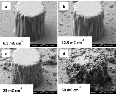
Figure 2. SEM image of the micro-pillars surface (pillar diameter 15µm spaced from 40µm) covered with electrodeposited fluorinated polymer films with different charge (from top left to bottom right: 6.5, 12.5, 25 and 50 mC.cm-2.
The wettability study was performed using purified water (Millipore). For high values of the contact angle hysteresis, the
6.5 mC cm-2 12.5 mC cm-2 25 mC cm-2 50 mC cm-2 a ) b
)
c d)
sliding drops method was not possible, even for drops tilted at 90°.
We have used a classical experimental sessile drop setup to measure advancing and receding contact angles from a side view of the sessile droplets. By using a syringe to increase and decrease the volume of the drop, we can measure respectively the advancing and receding contact angle. The measurement is done by image analysis using Image J (NIH, USA) software. We estimate the errors in the determination of contact angle on images with Image J to be +/- 1.5° for contact angle between 90° and 160° and +/- 2° for contact angle below 15°. We measure an average value at a certain distance from a pillar; which does not take into account the local evolution of the angle at the pillar scale.
Results and discussion
Surface morphology
SEM images of the polymer growth on the non-conductive pillars after different deposition charges (𝑸𝒔 = 6.5, 12.5, 25 and
50 mC.cm-2) are given in Figure 2. As expected, after a
deposition charge of 6.5 mC.cm-2, only the conductive areas
between the pillars were covered by a thin layer of polymer (Figure 2.a)). Then, the polymer could surprisingly growth not only between the pillars but also around the non-conductive pillars from the bottom to the top as 𝑸𝒔 increases.
Polymer deposition on non-conductive pillars. Hence, it was
possible to control the height of the lateral surface of pillars covered by the polymer. For example, for 𝑸𝒔= 12.5 mC.cm-2 and
𝑸𝒔= 25 mC.cm-2 only about 1/4 of the pillars (Figure 2.b)) and
3/4 of the pillars (Figure 2.c)), respectively, are covered by the polymer. As a consequence, the non-conductive pillars act as electrical resistors against the polymer growth. We plot on
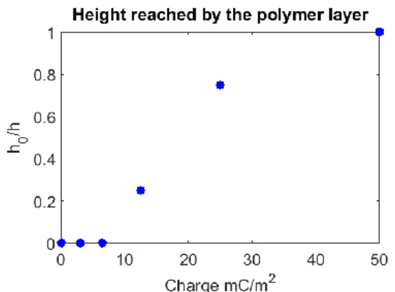
Figure 3 the height reached by the polymer layer 𝒉𝟎 on a pillar
of height 𝒉.
Figure 3. Height reached by the polymer layer as function of charge
Due to their exceptional polymerization capacity and their three-dimensional growth, these polymers were able to “colonize” even non-conductive areas. For 𝑸𝒔 = 50 mC.cm-2
almost all the non-conductive pillars are covered by the polymer. This is an important result because it is possible to control the polymer growth and stop the reaction when we want. This discovery opens new perspectives in the lithographic
processes to obtain patterns with different surface chemistry and roughness.
Global roughness. The growth by steps was confirmed by
roughness measurements. Table 1 gathers the mean (𝑹𝒂) and
quadratic (𝑹𝒒) roughness as a function of 𝑸𝒔.
𝑸𝒔 [mC.cm-2] 𝑹𝒂 [µm] 𝑹𝒒 [µm] 0 1,60 3,22 6,5 1,79 3,38 12,5 1,86 3,42 25 1,88 3,45 50 2,27 3,72
Table 1. Roughness parameters (𝑹𝒂 and 𝑹𝒒) as a function
deposition charge (𝑸𝒔) of the polymer electrodeposited on the
pillar surfaces
To interpret these measurements let us assume that the roughness is given in a simple approach by the formula:
𝑅𝑎= Φ(𝑄𝑠)ℎ0(𝑄𝑠) + (1 − Φ(𝑄𝑠))𝑅(𝑄𝑠)
where 𝒉 is the pillar height, 𝚽 the pillar density (projected surface fraction), given by 𝚽 = 𝝅 (𝟒𝒂𝒅𝟐𝟐), 𝒅 the pillar diameter, 𝒂 the distance between pillars and 𝑹 the average roughness of a flat polymerized surface for a given charge. Moreover, 𝚽, 𝒉𝟎 𝐚𝐧𝐝 𝑹
depend on the charge density 𝑸𝒔. Indeed, for low 𝑸𝒔, when the
polymerization occurs only at the bottom of the pillars, 𝚽, 𝐚𝐧𝐝 𝒉 have the same values as when no charge is applied. Thus, in this regime, 𝑹𝒂 increases only because of the increase in 𝑹
between the pillars. This regime is observed for 𝑸𝒔 between 0 and
6.5 mC.cm-2. Then, we observe that 𝑹
𝒂 increases more slowly
between 𝑸𝒔= 6.5 and 25 mC.cm-2. This corresponds to the polymer
climbing around the pillars without changing significantly 𝑹𝒂. This is
first because the apparatus is not able to analyze the roughness around the pillars and second because the deposited layer of polymers on pillar side is still thin and do not really change the pillar diameter, as it can be observed on figure 2. c)). Above 25 mC.cm-2,
the polymerization on the side and on top of the non-conductive pillars induces an important increase in the roughness because the polymer layer becomes large (Figure 2. d)) and thus 𝚽 increases by a few percent since the pillars diameter increases (about a few microns) and also 𝐡 increases by about the same amount.
In addition to the wetting properties, we can notice that the surfaces are translucent, and sufficiently transparent to allow the observation by transmission of sessile droplets and their contact lines.
Wetting properties with water
Effect of the charge. We present here the effect of the deposition
charge on the advancing and receding contact angles. All the measurements are summarized in Figure 4.
For the advancing angles, the values increase rapidly as charge increases to reach a plateau value for charge higher than 12.5 mC/cm2, and presents the same value, whatever the pillars density.
For the receding angles, the trend is the same: a global increase with the charge, although a plateau value is reached only for charge higher than 50 mC/cm2 and the transition to high contact angle
ARTICLE Journal Name
4 | J. Name., 2012, 00, 1-3 This journal is © The Royal Society of Chemistry 20xx
plateau is reached more progressively by increasing the charge between these two values.
At low charges (below 6 mC/cm2), the receding contact angle has
a low value, around 10° and the surfaces are very adhesives. For the surface with no pillars (0%), the transition is for even higher value of the charge (25 mC/cm2). This means that at 12.5
mC/cm2, adding pillars allows to increase the receding contact angle,
which can be explained by the higher value of the receding contact angle on the pillar material (SU-8 photoresist plus polymer layer). For higher charge values, the higher the pillar density is, the lower is the receding contact angle. This is due to the role of defect played by the pillars.
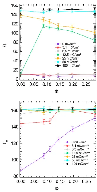
Figure 4. Advancing and Receding contact angle as function of the charge.
In addition, we can notice the proximity of the curve on Figure 4 with the classical result obtained by Dettre and Johnson on the effect of advancing and receding contact angles as function of the roughness for a homogeneous surface [17].
We have calculated the mean standard deviation for the contact angles for each series of surfaces for a given value of the electrodeposition charge, it is between +/- 0.6° to +/- 3.2°. We assume that this characterizes the variability due to differences on the surface state. We also have taken into account the errors expected due to the optical measurement method (between +/- 1° and +/- 2 ° ) and by adding to the standard deviation values, we obtained the error bars plotted on the graph of figures 4 and 5.
Effect of the (projected) surface fraction of pillars. On Figure 5, we
have plotted the effect of the pillar density (𝚽 = 𝝅 (𝒅𝟐
𝟒𝒂𝟐), see part 3.1) on the advancing and receding contact angle.
For the advancing contact angles, the values are always above 140° when the charge is strictly positive and even above 150° (superhydrophobic) for charge larger or equal to 6 mC/cm2. When
the charge is strictly positive, the global trend is that 𝜽𝒂 is slightly
increasing with 𝚽. For the surface with no charge (0 mC/cm2), the
angle is strongly increasing from 90° to 150°.
For the receding contact angle, at low charges (≤6 mC/cm2), the
values are constant, quite low (~10°) and they do not depend on the
pillar density. For 12.5 mC/cm2, contact angle of surfaces with no
pillar presents the same value than surfaces of lower charges, but as soon as pillars are present, the receding contact angle increases sharply to 115° for 𝚽 ~ 𝟎. 𝟎𝟔. Here, the high increase in receding contact angle up to 115° can be explained by the fact that the polymer layer grows around the pillars, which reduces the hydrophilic part of the pillar compared to situation of low charges.
Figure 5. Receding (Up) and Advancing (Down) Contact angle as function of the surface fraction of pillars.
Thus the pinning of the contact line induced by pillars is also reduced. Then for even higher pillar density (between . 𝟎𝟔 𝐚𝐧𝐝 𝟎. 𝟐𝟏) , the receding angle decreases slowly until 85°. This decrease is expected because the top of the pillars is hydrophilic (in receding conditions). Thus, the higher the pillar surface fraction is, the lower the contact angle is. For higher charge (25 mC/cm2), the
trend is the same, the highest value is for 0% pillars, and then as pillar density is increased, the receding angle decreases. For even higher charges (above 50 mC/cm²), the value is high (above 145°)
independently of the pillar density, dominated by the electrodeposited polymer layer that covers most of the surface.
Discussion
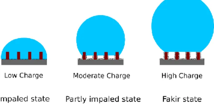
As we will see below, advancing and receding contact angle measurements presented in the previous section suggest that the drop may be in three possible states which are described in figure 6: 1/ in a classical impaled state as described by Wenzel where the water fully impregnate the space between pillars, 2/ in an intermediate situation where the drop is partly impaled with an interface stabilized at the height reached by the polymer layer (as shown in Figure 2 and 3) and 3/ in the classical “fakir” state, where the drop is sited on the top of the pillars. For low electrodeposition charge (≤6,5mC/cm2). First, we can notice that, on average, the
polymeric pillars are hydrophobic enough for advancing line because advancing contact angle is quite large and increases with 𝜙.
In addition, the receding contact angle remains constant at a low value since for a receding line, the pillars present contact angle lower than 90° (hydrophilicity). Thus, the hysteresis increases with 𝜙 as it is predicted for an impaled drop on a rough surface (see purple and red curves on plots of figure 5). Secondly, advancing contact angles reaches a plateau when the charge increases, more and more quickly when 𝜙 increases. Indeed, the larger the charge is, the more hydrophobic pillars are, leading to an increase of the contact angle. Also, the higher the pillars density, the higher the roughness, and following Wenzel law, the higher the contact angle. Hence, for low deposition charge, the drop should be in impaled state, described by Wenzel model. The pillar walls are poorly covered by polymer, but the base surface is superhydrophobic, leading to a low adhesion on the surface between pillars.
Figure 6. Hybrid surfaces in fakir, intermediate and impaled states.
For intermediate value of electrodeposition charge (12.5 - 25 mC/cm2), we can notice a transition in the drop wetting behavior (see
green and yellow curves on graphs on figure 5). For 𝑪 = 𝟏𝟐. 𝟓 mC/cm², we see that the advancing contact angle has reached the plateau for all 𝜙 and that the receding contact angles goes from 10° to 115° when just a small number of pillars have been added. This means that for 12,5 mC/cm², the surface is very hydrophobic (a thin layer of polymers is deposited on the bottom) but the roughness is really small when there is no pillars and so the hysteresis is very large as predicted by Johnson and Dettre [17]. As soon as the pillars are added, the roughness increased suddenly which explains the
jump in receding contact angle and so an important reduction of the contact angle hysteresis. However, the receding contact angle decreases when 𝜙 increases while the advancing contact angle is constant, then again, the hysteresis increases with 𝜙, pillars being still defects on which the drop is pinned. For 𝑪 = 𝟐𝟓 mC/cm², this pinning is even smaller because receding contact angles are larger but still decrease with 𝜙. This suggests that the drop is then partly impaled on the pillars, owing to the contact angles values and their variation with 𝜙. If it was in Fakir state, the contact angle value would be higher than 100 or 120°, when the local contact angle is not so hydrophobic, the drop do not stay at the top of the pillars but wet them down. If it was in complete impaled state (Wenzel), the angle would increase with 𝜙. The surface area of the impregnated part of the pillars decreases when C increases. The reason is that the lateral surface of the bottom part of the pillars is covered with polymers up to a height that increases with C (see figure 2 c and figure 3.). Even if we do not have direct visualization (out of the scope of this study), the drop base must then lie at the height reached by the polymer layer on the pillars’ vertical walls, which is a zone of strong change of local contact angle. This is an important result because we see here that we can tune this particular state (intermediate impalement) by controlling the electrodeposition charge. In [29], the authors have described two transitions on multi scale roughness surfaces, from micro-Cassie to Wenzel or from micro-Cassie to nano-Cassie, the latter being reversible and can present as in the present study partially impaled states.
For higher electrodeposition charge (≥50mC/cm²), both advancing and receding contact angles are high, and the hysteresis is very low. This is well expected because in this case, the pillars are completely covered with the polymers and so we retrieve the results of Darmanin et al. [28]. The drop is in the classical “fakir” state.
We can notice that both contact angles are constant with 𝜙 which is in well agreement with experiments in Dubov et al. [30] for the advancing contact line. For the receding case, experiments and models of [30] and [31] predict that the receding contact angle of a fakir drop on a regular pillar surface should depends on pillars fraction. This is not the case here for our values of receding contact angle. This difference could come from the rough nature of the pillars due to the polymers compared [30] and [31] for which pillars are smooth. The case of high electrodeposition charges can be reduced to the case of rough micro-pillar surfaces (two-roughness surfaces). Receding contact angles that we measured are consistent with results reported in [32] and [33] on such surfaces. The authors also observed contact angles that do not depend on the pillar surface fraction when the surface presents two roughness. The retraction of the contact line is then different of the one of more regular smooth pillar surfaces. Indeed, it has been recently showed on smooth pillar surfaces that receding contact angles decrease linearly with 𝜙 and that this behaviour can be explained by the formation of “kinks” (deformations of the liquid interface imposed by the contact line pinning on the pillar) [34, 31]. We think that the kinks are really less important in the case of rough pillars because the local state of the contact line on the rough pillars differs from the one on smooth pillars as it was shown in the studies of [29] and [35]. We think that
ARTICLE Journal Name
6 | J. Name., 2012, 00, 1-3 This journal is © The Royal Society of Chemistry 20xx
for two roughness surfaces, the contact line can go down and up along the pillars with low pinning force that must change the contact line retraction dynamics. A more complete studies of this must be done and is out of the scope of the present paper. However, the hybrid surfaces that we present here, for which roughness can be controlled along the pillar appears as a model system to further study the effect of roughness on the displacement of the contact line on partial or complete rough pillars.
The fabrication of mixed surface allows to fabricate substrate with high advancing angle for almost any charge, but a varying receding angle on a broad range of charge. By tuning the charge, the contact angle hysteresis can be tuned from 10° (100 mC.cm-2) to 150°
(3 – 6 mC.cm-2).
Conclusions
We have fabricated hybrid surfaces with pillars and the base surface between them presenting different local contact angles. The electrodeposition of conducting polymers is realized only from the conductive base surface. As the polymer quantity increases (the charge) since it develops from the conducting part, the pillars are covered more and more from their bottom to their top. We measured the surfaces’ wetting properties. For large charge values, we retrieve the wetting of surfaces with pillars fully covered by polymers as in [28] where the whole surface was conductive. For such fully superhydrophobic surface, contact angles measurements are in good agreement for advancing contact angle with experiments and model of [30] but present deviation for the receding contact angle for which [30] and [31] predict a dependence with 𝜙. Those differences must be due to the roughness of the pillars themselves as observed by [29] and [35]. We show then that a tuning of receding and advancing contact angle can be realized by varying pillar density and/or charge value. We interpret these results assuming that the droplets can be in three states: fakir / fully impaled / but also partly impaled. We assume that looking at the values of contact angles and their evolution with pillars density, only fakir and fully impaled states cannot explain the measured values. This partly impaled state is here directly induced by the hybrid nature of the surface and the height reached by the polymers along the pillars. This is an original result of our method which allows a tuning of the hysteresis value over a broad range.
Conflicts of interest
“There are no conflicts to declare”.
Acknowledgements
We thank the CNRS and region PACA (project COMPLEXWET) for funding.
Notes and references
1 W. Barthlott, C. Neinhuis, Planta, 1997, 202, 1–8. 2 X. Gao, L. Jiang, Nature, 2004, 432, 36–36.
3 P. Roach, N. J. Shirtcliffe, M. I. Newton, Soft Matter, 2008, 4, 224-240.
4 E. Celia, T. Darmanin, E. Taffin de Givenchy et al., J. of Coll. and Interf. Science, 2013, 402, 1-18.
5 A. Y. Vorobyev, C. Guo, J. of App Phys, 2015, 117, 033103. 6 P. Aussillous, D. Quéré, Nature, 2001, 411, 924-927.
7 L. Mahadevan, Y. Pomeau, Phys Fluids, 1999, 11(9), 2449-2453.
8 C. Cottin-Bizonne, J. L. Barrat, L. Bocquet, E. Charlaix, Nature Materials, 2003, 2(4), 237-240.
9 A. Lafuma, D. Quéré, Nature Materials, 2003, 2, 457-460. 10 J. Ou, B. Perot, J.P. Rothstein, Phys Fluids, 2004, 16,
4635-4643.
11 M. C. Reyssat, Splendeur et misère de l'effet lotus (Doctoral dissertation, Université Pierre et Marie Curie-Paris VI), 2007. 12 Y. Jung, B. Bhushan, Langmuir, 2008, 24, 6262-6269.
13 B. Bhushan, M. Nosonovsky, Philos Trans A Math Phys Eng Sci, 2010, 368, 4713-4728.
14 M. A. Sarshar, C. Swarctz, S. Hunter, J. Simpson, C. Choi, Colloid Polym Sci, 2013, 291, 427–435.
15 M. Nosonovsky, B. Bhushan, Current Opinion in Colloid & Interface Science, 2009, 14(4), 270-280.
16 X. Yao, Y. Song, L. Jiang, Advanced materials, 2011, 23, 6 , 719-734.
17 R.E. Johnson, R.H. Dettre, Advances in Chemistry Series, 1964,
43, 112.
18 R. N. Wenzel, Ind Eng Chem, 1936, 28, 988-994. 19 A. Cassie, S. Baxter, T Faraday Soc, 1944, 40, 546-551. 20 A. Marmur, Soft Matter, 2012, 8, 6867.
21 A. Betz, J. Xu, H. Qiu, Appl Phys Lett, 2010, 97, 141909. 22 J L Wilbur, A. Kumar, E. Kim, G. M. Whitesides, Adv Mater,
1994, 6(7‐8), 600-604.
23 K. Varanasiet, M. Hsu, N. Bhate, W. Yang, T. Deng, Appl Phys Lett, 2009, 95(9), 094101.
24 L. Mishchenko, M. Khan, J. Aizenberg, B. D. Hatton, Adv.Func. Materials, 2013, 23(36), 4577-84.
25 C. W. Yao, J. Alvarado, C. P. Marsh, B. G. Jones, M. K. Collins, Appl Surf Sci, 2014, 290, 59-65.
26 L. Mammen, K. Bley, P. Papadopoulos, F. Schellenberger, N. Encinas, H. Butt, Soft Matter, 2015, 11, 506.
27 T. Darmanin, E. Taffin de Givenchy, S. Amigoni et al., Adv. Materials, 2013, 25(10), 1378-1394.
28 T. Darmanin, F. Guittard, S. Amigoni, E. Tafin de Givenchy, X. Noblin, R. Kofman, F. Celestini, Soft Matter, 2011, 7, 1053– 1057.
29 T. Verho, J. T. Korhonen, L. Sainiemi, V. Jokinen, C. Bower, K. Franze, S. Franssila, P. Andrew, O. Ikkala, R. H. A. Ras, PNAS, 2012, 109, 10210-10212.
30 A.L. Dubov, J. Teisseire, E. Barthel. Eur. Letters, 2012, 97, 26003.
31 M. Rivetti, J. Teisseire, E. Barthel, Physical review letters, 2015,
115(1), 016101.
32 [He2011] He Y, Jiang C, Yin H, Yuan W, Tailoring the wettability of patterned silicon surfaces with dual-scale pillars: from hydrophilicity to superhydrophobicity, Applied Surface Science, 257(17), 7689-7692, (2011).
33 [Zhu2005] Zhu L, Xiu Y, Xu J, Tamirisa P A, Hess D W, Wong C P, Superhydrophobicity on two-tier rough surfaces fabricated by controlled growth of aligned carbon nanotube arrays coated with fluorocarbon, Langmuir, 21(24), 11208-11212, (2005).
34 [Gauthier2013] Gauthier A, Rivetti M, Teisseire J, Barthel E, Role of kinks in the dynamics of contact lines receding on superhydrophobic surfaces, Physical review letters, 110(4), 046101 (2013).
35 Paxson A T, Varanasi K K, Self-similarity of contact line depinning from textured surfaces, Nature communications, 4, 1492, (2013).