Lessons Learned in the Use of Fiber Optic Sensor for
Civil Structural Monitoring
D. Inaudi1'2, N. Casanova1, B. Glisic1, S. Vurpillot1'2, P. Kronenberg2 and S. LLoret2
' S M A R T E C SA, Via al Molino 6,CH-6916 G R A N C I A , Switzerland 2I M A C - D G C - EPFL, CH-1015 Lausanne Switzerland
Abstract
From many points of view, fiber optic sensors are the ideal transducers for civil structural monitoring. Being durable, stable and insensitive to external perturbati-ons, they are particularly interesting for the long-term health assessment of civil structures. On the other hand, the small size and the relative fragility of the naked fibers are apparently incompatible with the hostile environment usually found in civil engineering building sites. In this contribution we will, however, show that with adequate packaging and careful design of the sensors and their accessories, fiber optic sensors can match and surpass conventional sensors, not only in their measurement performance, but also in the ease of use and survivability. This paper resumes the nine year long experience of our group in the installation of fiber optic sensors in the most diverse structure types, including bridges, tunnels, dams, piles, anchors, historical monuments, nuclear power plants and many others. To date, we have installed about Γ300 sensors in almost 70 different applications. Statistics show that, by proper handling, it is possible to achieve 95-100% survivability during installation and for many years afterward.
Erfahrungen aus der Anwendung faseroptischer Sonden für die Über-wachung von Tragwerken
Zusammenfassung
Es gibt viele Gründe dafür, warum faseroptische Sonden ideale Messwertgeber für die Überwachung von Tragwerken sind. Da sie dauerhaft, stabil und unempfind-lich gegen äussere Störungen sind, ist ihr Einsatz für die Langzeit-Zustandserfas-sung von Tragwerken von besonderem Interesse. Auf der anderen Seite scheinen die kleinen Abmessungen und die Zerbrechlichkeit der ungeschützten Fasern unverträglich mit der rauhen Umgebung auf einer üblichen Baustelle zu sein. In diesem Beitrag werden wir jedoch zeigen, dass faseroptische Sonden, wenn sie nur korrekt eingepackt sind und sorgfältig aufgebaut sind, ebenso gut oder besser als herkömmliche Sonden sind. Dies betrifft nicht nur die Messgenauigkeit, sondern in gleichem Mass die leichte Handhabung und die Uberlebenschancen. In diesem Beitrag wird die neunjährige Erfahrung unserer Gruppe beim Einbau von faserop-tischen Sonden in unterschiedlichste Tragwerke und Bauteile, wie etwa Brücken, Tunnel, Staudämme, Pfähle, Anker, historische Baudenkmale oder Kernkraftwerke zusammengefasst. Bis heute haben wir etwa 1.300 Sonden in nahezu 70 unter-schiedliche Objekte eingebaut. Eine statistische Auswertung zeigt, dass bei ord-nungsgemässem Einbau 95 bis 100% überleben und viele Jahre betriebsbereit bleiben.
Stichwörter: Faseroptische Sonden, Betontragwerke, historische Baudenkmale
Received: 15th November, 2000 Accepted: 14th December, 2000
1 Introduction
The first building block of a typical health monitoring system is constituted by a network of sensors that measure the parameters relevant to the state of the structure and its environment. For civil structures such as bridges, tunnels, dams, geostruc-tures, power plants, high-rise buildings and historical monuments, the most rele-vant parameters are:
• Physical quantities: position, deformations, inclinations, strains, forces, pressures, accelerations, vibrations.
• Temperatures.
• Chemical quantities: humidity, pH, chloride concentration.
• Environmental parameters: air temperature, wind speed and direction, irradiation, precipitation, snow accumulation, water levels and flow, pol-lutant concentration.
Conventional sensors based on mechanical and/or electrical transducers are able to measure most of these parameters. In the last few years, fiber optic sensors have made a slow but significant entrance in the sensor panorama. After an initial euphoric phase when optical fiber sensors seemed on the verge of invading the whole world of sensing, it appears now that this technology is only attractive in the cases where it offers superior performance compared to the more proven conven-tional sensors. The addiconven-tional value can include an improved quality of the measu-rements, a better reliability, the possibility of replacing manual readings and opera-tor judgment with automatic measurements, an easier installation and maintenance or a lower lifetime cost. The first successful industrial applications of fiber optic sensors to civil structural monitoring demonstrate that this technology is now suf-ficiently mature for a routine use and that it can compete as a peer with conventio-nal instrumentation.
2 Fiber Optic Sensor Types 2.1 General remarks
There is a great variety of fiber optic sensors [1-4] for structural monitoring in both the academic and the industrial areas.
Unlike the USA, where most efforts seem concentrated to strain sensing, Europe is developing and producing a more varied mix of sensors for the most dis-parate types of measurement and application. In this overview we will concentrate on sensors for civil health monitoring that have reached an industrial level or are at
Table 1 : Fiber optic sensors for civil structural monitoring (a partial European perspective)
Measured
Parameters Maturity
Active groups in Europe (see text for
details) Units installed S O F O Displacement Commercial S M A R T E C , IMAC-EPFL 1300+
Microbending Displacement Commercial DehaCom hundreds Bragg gratings Strain,
temperature, (displacement)
Field trials Stabilos project, LETI, EMPA, Uni. Cantabria, Uni. Leipzig and many others
hundreds
Fabry-Perot Strain Field trials BAM tens Raman Distributed
temperature
Commercial York Sensors, G E S O tens
Brillouin Distributed temperature and strain
Field trials MET-EPFL, Omnisens units
Hydrogel Humidity, water ingress
Field trials Univ. of Strathclyde units
2.2 SOFO Displacement Sensors
The SOFO system (see Fig. 1) is a fiber optic displacement sensor with a resolu-tion in the micrometer range and an excellent long-term stability. It was developed at the Swiss Federal Institute of Technology in Lausanne (EPFL) and is now com-mercialized by SMARTEC in Switzerland [5-7] (see Fig. 2).
The measurement set-up uses low-coherence interferometry to measure the length difference between two optical fibers installed on the structure to be monito-red. The measurement fiber is pre-tensioned and mechanically coupled to the struc-ture at two anchorage points in order to follow its deformations, while the reference fiber is free and acts as temperature reference. Both fibers are installed inside the same pipe and the measurement basis can be chosen between 200mm and 10m.
The resolution of the system is of 2 μπι independently from the measurement basis and its precision of 0.2% of the measured deformation even over years of ope-ration.
Structure
Figure 1 : S O F O S y s t e m Set-up
Figure 3: SOFO Sensor Installed on a Church Vault
The SOFO system has been successfully used to monitor more than 50 structures, including bridges, tunnels, piles, anchored walls, dams, historical monuments (see Fig. 3), nuclear power plants as well as laboratory models.
2.3 Microbending Displacement Sensors
An alternative fiber optic sensor useful for the measurement of length variations is based on the principle of microbending. In that set-up, an optical fiber is twisted with one ore more other fibers or with metallic wires [8] along its sensing length (see Fig. 4). When this fiber optic twisted pair is elongated the fibers will induce
bending in one-another and cause part of the light to escape the fiber. By measu-ring the intensity of the transmitted light it is therefore possible to reconstruct the deformation undergone by the structure on which the sensor is mounted.
A system based on this principle has been marketed for some years through Sicom and more recently by Deha-Com in France. This system was one of the ear-liest commercial applications of fiber optic sensors for the monitoring of civil struc-tures and was installed in different bridges, tunnels and high-rise strucstruc-tures. Typi-cally obtainable resolutions are of 30 μηι for short periods (below one day) and 100 μηι for the long-term. Arrangements measuring the reflected light intensity with an optical time reflectometer (OTDR) have also been proposed. These set-ups potenti-ally allow for distributed deformation measurements.
Microbending sensors are conceptually simple, however temperature compen-sation, intensity drifts, system calibration and the inherently non-linear relationship between intensity and elongation still present some challenges. This type of sensor seems particularly appropriate for short-term and dynamic monitoring as well as for issuing alarms.
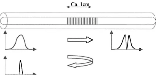
2.4 Bragg Grating Strain Sensors
Bragg gratings are periodic alterations in the index of refraction of the fiber core that can be produced by adequately exposing the fiber to intense UV light. The produced gratings typically have length of the order of 10 mm (see Fig. 5). If
Λ C a . l c n y
Λ
ί>
JL·
A
white light is injected in the fiber containing the grating, the wavelength corre-sponding to the grating pitch will be reflected while all other wavelengths will pass through the grating undisturbed. Since the grating period is strain and temperature dependent, it becomes possible to measure these two parameters by analyzing the spectrum of the reflected light [9]. This is typically done using a tunable filter (such as a Fabry-Perot cavity) or a spectrometer. Resolutions of the order of 1 με and 0.1 °C can be achieved with the best demodulators. If strain and temperature variations are expected simultaneously, it is necessary to use a free reference gra-ting that measures the temperature alone and use its reading to correct the strain values. Set-ups allowing the simultaneous measurement of strain and temperature have been proposed, but have yet to prove their reliability in field conditions. The main interest in using Bragg gratings resides in their multiplexing potential. Many gratings can be written in the same fiber at different locations and tuned to reflect at different wavelengths. This allows the measurement of strain at different places along a fiber using a single cable. Typically, 4 to 16 gratings can be measured on a single fiber line. It has to be noticed that since the gratings have to share the spec-trum of the source used to illuminate them, there is a trade-off between the number of grating and the dynamic range of the measurements on each of them.
Because of their length, fiber Bragg gratings can be used as replacement of con-ventional strain gages and installed by gluing them on metals and other smooth sur-faces [10]. With adequate packaging they can also be used to measure strains in con-crete over basis length of typically 100 mm.
A large number of research and development projects for this type of sensors are underway worldwide and Europe is by no mean an exception to this trend [11]. Two European projects (STABILOS [ 12] and COSMUS) focus on the application of this technology to the measurement of movements in tunnels, mines and other geostructures. In particular, an array of Bragg grating has been installed in the Mont Terri tunnel in Switzerland. The LETI group in France has also used this technology to monitored lock gates [13] and is introducing the system in the nuclear power industry [14], while EMPA (Swiss Federal Laboratories for Materials Testing and Research) has installed them in the Luzzone Dam [15] and in a cable-stayed bridge. Finally, the University of Cantabria in Spain is developing sensors for the electrical power generation industry including strain and acceleration sensors (also base on other sensing techniques) [16]. A comprehensive review by Pierre Ferdinand on the applications of Bragg gratings in Europe can be found in the references [11].
2.5 Fabry-Perot Strain Sensors
Extrinsic Fabry-Perot Interferometers (EFPI) are constituted by a capillary silica tube containing two cleaved optical fibers facing each others, but leaving an air gap of a few microns or tens of microns between them (see Fig. 6). When light is laun-ched into one of the fibers, a back-reflected interference signal is obtained. This is
Ca. 1cm
it-Figure 6: Extrinsic Fabry-Perot Interferometers Functional Principle
due to the reflection of the incoming light on the glass-to-air and on air-to-glass interfaces. This interference can be demodulated using coherent or low-coherence techniques to reconstruct the changes in the fiber spacing. Since the two fibers are attached to the capillary tube near its two extremities (with a typical spacing of 10 mm), the gap change will correspond to the average strain variation between the two attachment points [1,9].
Contrary to the rest of the world, Europe seems to pay relatively little attention to this interesting sensor technique. A notable exception is the group at BAM in Ber-lin (Germany), which is using these sensors to monitor the early-age deformations of mortars [17] and has applied them to the monitoring of a concrete bridge in Char-lottenbourg [18].
2.6 Raman Distributed Temperature Sensors
Raman scattering is the result of a non-linear interaction between the light trave-ling in a fiber and silica. When an intense light signal is shined into the fiber, two frequency-shifted components called respectively Raman Stokes and Raman anti-Stokes, will appear in the back-scattered spectrum. The relative intensity of these two components depends on the local temperature of the fiber. If the light signal is pulsed and the back-scattered intensity is recorded as a function of the round-trip time, it becomes possible to obtain a temperature profile along the fiber [19]. A system based on Raman scattering is commercialized by York Sensors in the UK. Typically a temperature resolution of the order of 1 °C and a spatial resolu-tion of less than l m over a measurement range up to 10 km is obtained for multi-mode fibers. A new system based on the use of singlemode fibers should extend the range to about 30km with a spatial resolution of 8 m and a temperature resolution of 2°C.
These systems have been successfully used by GESO in Germany to detect leaks in dams and pipelines.
2.7 Brillouin Distributed Temperature Sensors
Brillouin scattering sensors show an interesting potential for distributed strain and temperature monitoring [20]. Systems able to measure strain or temperature varia-tions of fibers with length up to 50 km with spatial resolution down in the meter range are now demonstrating their potential in the first field trials. For temperature measurements, the Brillouin sensor is a strong competitor to systems based on Raman scattering, while for strain measurements it has practically no rivals.
Brillouin scattering is the result of the interaction between optical and sound waves in optical fibers. Thermally excited acoustic waves (phonons) produce a peri-odic modulation of the refractive index. Brillouin scattering occurs when light pro-pagating in the fiber is diffracted backward by this moving grating, giving rise to a frequency shifted component by a phenomenon similar to the Doppler shift. This process is called spontaneous Brillouin scattering.
Acoustic waves can also be generated by injecting in the fiber two counter-pro-pagating waves with a frequency difference equal to the Brillouin shift. Through electrostriction, these two waves will give rise to a traveling acoustic wave that rein-forces the phonon population. This process is called stimulated Brillouin amplifica-tion. If the probe signal consists in a short light pulse and its reflected intensity is plotted against its time of flight and frequency shift, it will be possible to obtain a profile of the Brillouin shift along the fiber length.
The most interesting aspect of Brillouin scattering for sensing applications resi-des in the temperature and strain dependence of the Brillouin shift [21]. This is the result of the change the acoustic velocity according to variation in the silica density. The measurement of the Brillouin shift can be approached using spontaneous or sti-mulated scattering. The main challenge in using spontaneous Brillouin scattering for sensing applications resides in the extremely low level of the detected signal. This requires sophisticated signal processing and relatively long integration times. A commercial system based on spontaneous Brillouin scattering is available from A N D O (Japan).
Systems based on the stimulated Brillouin amplification have the advantage of working with a relatively stronger signal but face another challenge. To produce a meaningful signal the two counter-propagating waves must maintain an extremely stable frequency difference. This usually requires the synchronization of two laser sources that must inject the two signals at the opposite ends of the fiber under test. The MET (Metrology laboratory) group at Swiss Federal Institute of Technology in Lausanne (EPFL) proposed a more elegant approach [22]. It consists in generating both waves from a single laser source using an integrated optics modulator. This arrangement offers the advantage of eliminating the need for two lasers and intrin-sically insures that the frequency difference remains stable independently from the laser drift. Omnisens and SMARTEC (Switzerland) commercialize a system based on this principle. It features a measurement range of 10 km with a spatial resolution
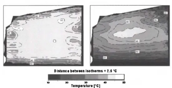
Distance between i s o t h e r m s = 2.5 °C
3d 30 40
T e m p e r a t u r e [°C]
Figure 7: Luzzone Dam:Temperature Distribution Measured with the Brillouin System 15 and 55 Days after Concrete Pouring (Courtesy of L. Thevenaz and Ph. Robert, MET-EPFL, Switzerland)
of 1 m or a range of 100 km with a resolution of 10 m. The strain resolution is 20 με and the temperature resolution 1°C. The system is portable and can be used for field applications (see Fig. 7). These values are close to the theoretical limits of a Brillouin system.
Since the Brillouin frequency shift depends on both the local strain and tempe-rature of the fiber, the sensor set-up will determine the actual sensitivity of the system. For measuring temperatures it is sufficient to use a standard telecommuni-cation cable. These cables are designed to shield the optical fibers from an elonga-tion of the cable. The fiber will therefore remain in its unstrained state and the quency shifts can be unambiguously assigned to temperature variations. If the fre-quency shift of the fiber is known at a reference temperature it will be possible to calculate the absolute temperature at any point along the fiber. Measuring distribu-ted strains requires a specially designed sensor. A mechanical coupling between the sensor and the host structure along the whole length of the fiber has to be guaran-teed. To resolve the cross-sensitivity to temperature variations, it is also necessary to install a reference fiber along the strain sensor. Similarly to the temperature case, knowing the frequency shift of the unstrained fiber will allow an absolute strain measurement.
2.8 Hydrogel Distributed Humidity Sensors
Many of the degradations that can occur to the most used structural materials: con-crete and steel, have a chemical origin. It is therefore interesting to monitor the moisture content and the concentration of potentially harmful chemicals such as chloride as well as the variations of pH. Chemical measurements with fiber optic sensors are much less developed than those of physical parameters and tempera-ture. It is therefore interesting to cite the development of a distributed humidity sensor that is based on the use of a particular hydrogel capable of transforming a humidity variation in a change in its dimensions [23]. This allows the transforma-tion of a difficult chemical measurement in a much easier strain or elongatransforma-tion mea-surement. A first sensor, developed at Strathclyde University, is based on a hydro-gel that swells when wetted. The expansion of the hydrohydro-gel induces microbending losses in an optical fiber that can be detected with a standard Optical Time Domain Interferometer (OTDR). The system shows potential for measurement of water ingress and humidity in large structures and in areas that are difficult to inspect. In one of the first field demonstrations, the system was used to detect an incomplete grouting of a post-tensioning cable duct [24], By using another type of hydrogel, it is expected that this type of sensors will be capable of measuring other chemical parameters and in particular the pH chances associated with carbonation in con-crete.
3 Installing Fiber Optic Sensors in Civil Engineering Structures
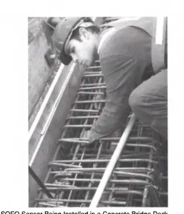
Since different type of structures and different materials need specific sensors, sen-sor packaging has to be adapted to each particular application. In our group, efforts have been directed towards the development of a reliable sensor for new concrete structures (see Fig. 8 and Fig. 9), but some tests were also conducted on metallic and timber structures, as well as on existing structures where only surface installa-tion was possible. The following remarks are based on our experience with the installation of SOFO sensors, but can be viewed as more general regarding the use of FOS (Fiber Optic Sensor) in civil structural monitoring.
The sensor must respond to different requirement both from the optical point of view as on its mechanical solidity and transmission of the displacements from the structure to the fiber.
Optical requirements: The sensor has to encode a displacement of the structure into a change of the length of an optical fiber. On the other hand, optical fibers pre-sent a disturbing cross-sensitivity to temperature changes and to obtain a pure dis-placement or strain reading it is necessary to compensate for this effect. The easiest way to achieve this aim is to use one measurement fiber following the structure dis-placement and one reference fiber independent of it. Obviously, the fibers have to be intact and microbending must be reduced to minimize the losses.
Figure 8: SOFO Sensor Being Installed in a Concrete Bridge Deck
Mechanical requirements: The measurement fiber has to be in mechanical contact with the host structure. All axial displacements have to be transferred from the host structure to the fiber. Creep effects have to be avoided since the final aim of the system is long-term measurements. It was found that using polyimide coated fibers and epoxy glues it was possible to obtain an excellent mechanical coupling bet-ween the fiber and the anchorage. The long-term solidity of the fibers has to be guaranteed by avoiding any induced brittleness of the fibers due to superficial micro-cracks. The fiber coating has to be removed only when strictly necessary and only on fiber sections that are not under permanent tension in the sensor. Extensive data is available on the long-term durability of optical fibers installed in telecommunication cables under small tensions. If the strain of the fiber does not exceed 0.5%, the fiber should have a typical life of more than 40 years before a failure is likely to occur. Thermal and mechanical fatigue can also decrease the life span of the fibers. We have successfully fatigue tested SOFO sensors for more than 18 millions cycles (corresponding to 40 years in a highway bridge) and with amplitudes of a few mm typical for concrete structures.
The reference fiber is supposed to be unaffected by the structure displacements and change its optical length only under the influence of temperature variations.
Figure 9: Bundle of SOFO Sensors Ready for Installation in a Pile for Lateral Friction Analysis
Furthermore it is important that the measurement fiber and the reference fiber always have the same temperature locally. This will greatly reduce the parasite sen-sitivities in the temperature. Installing the reference fiber freely inside the same pipe housing the measurement fiber satisfies these requirements. This fiber has an extra length and will therefore remain unstressed when pre-stressing is applied to the measurement fiber.
Environmental requirements: The sensor has to survive the construction and, if possible, the whole live span of the structure. During the construction phases the sensor is exposed to a hostile environment and has therefore to be rugged enough to protect the fibers from external agent.
Chemical aggression has to be taken into account since concrete can be particu-larly aggressive because of its high alkalinity. These requirements are often contra-sting with the ones of the previous point. To protect the fiber one tends to isolate if from the environment by using thicker or multiple layers of coating. This has the side effect to impede the strain transmission from the structure to the fiber. Finally, the sensor must be easy to use by inexperienced persons and has to be installed rapidly without major disturbance to the building yard schedule. The standard SOFO sensors respond to all these requirements. They can either be embedded into concrete, installed on the surface of an existing structure or secured inside a boreh-ole by grouting. We have fabricated and installed more than 1400 such sensors with
Figure 10: Connection Box for Mating Sensor Cable with Multi-fiber Extension Cables
a survival rate between 90% and 100% depending on the type of application. In our experience, the survival of sensors depends not only on the reliability of the sensor packaging, but also on the careful design of the installation details and in particular of the connections (cable ingress and egress points, connectors, extension cables, connection boxes, cable ducts, ...), (see Fig. 10 and Fig. 11).
4 Conclusions
The monitoring of new and existing structures is one of the essential tools for a modern and efficient management of the infrastructure network. Sensors are the first building block in the monitoring chain and are responsible for the accuracy and reliability of the data. Progress in the sensing technology can therefore be focused to more accurate measurements, but also to systems that are easier to install, use and maintain. In the recent years, fiber optic sensors have moved the first steps in structural monitoring and in particular in civil engineering. Different sensing technologies have emerged and quite a few have evolved into commercial products.
It is difficult to find a common reason for the success of so diverse types of sen-sors. Each one seems to have found a niche where it can offer performance that sur-pass or complement the ones of the more traditional sensors. If three characteristics
Figure 11: SOFO Sensors with Protection Pipe Mounted and Removed
of fiber optic sensors should be highlighted as the probable reason of their present and future success, we would cite the stability of the measurements, the potential long-term reliability of the fibers and the possibility of performing distributed and remote measurements.
The success of fiber optic sensors depends not only on the underlying optical technology, but even more on the ability of practically and reliably installing the sensors in real structures, with minimum disturbance to the construction progress or the normal operation of the structure. To achieve these goals it is important to develop ad-hoc packaging and accessories (cables, junction boxes, etc.) that make it possible for non-specialists to use fiber optic sensors in the field.
References
1. E. Udd, Fiber Optic Sensors, Wiley, New York (1991)*An excellent intro-duction to fiber optic sensors.
2. E. Udd, Fiber Optic Smart Structures, Wiley, New York (1995) *An over-view of the applications of fiber optic sensors to structural monitoring.
3. D. Inaudi, Fiber Optic Smart Sensing, in Optical Measurement Techniques and Applications, P. K. Rastogi, Editor, Artech House, pp. 255-275 (1997) 4. Proceedings of the Optical Fiber Sensor (OFS) Series. The latest being:
"12t h International Conference on Optical Fiber Sensors", Williamsburg USA, October 1997, OS A 1997 Technical Digest Series Vol. 16.
5. D. Inaudi, A. Elamari, L. Pflug, Ν. Gisin, J. Breguet, S. Vurpillot,
Low-cohe-rence Deformation Sensors for the Monitoring of Civil-engineering Struc-tures, Sensor and Actuators A, Vol. 44, pp. 125-130 (1994)
6. D. Inaudi, Field Testing and Application of Fiber Optic Displacement
Sen-sors in Civil Structures, 12th International conference on OFS '97- Optical Fiber Sensors, Williamsburg, OS A Technical Digest Series, Vol. 16, pp. 5 9 6 - 5 9 9 ( 1 9 9 7 )
7. D. Inaudi, N. Casanova, P. Kronenberg, S. Marazzi, S. Vurpillot, Embedded
and Surface Mounted Fiber Optic Sensors for Civil Structural Monitoring,
Smart Structures and Materials Conference, San Diego, SPIE Vol. 3044, pp. 236-243 (1997)
8. L. Falco, O. Parriaux, Structural Metal Coatings for Distributed Fiber
Sen-sors, Opt. Fiber Sens. Conf. Proc., pp. 254, (1992)
9. A. Kersey, Optical Fiber Sensors, in Optical Measurement Techniques and Applications, P. K. Rastogi, Editor, Artech House, pp. 217-254 (1997) *A good and compact description of the most important fiber optic sensor types with emphasis on fiber Bragg Gratings.
10. S. T. Vohra, B. Althouse, Gregg Johnson, S. Vurpillot and D. Inaudi,
Quasi-static Strain Monitoring During the Push Phase of a Box-girder Bridge Using Fiber Bragg Grating Sensors, European Workshop on Optical
Fibre Sensors, Peebls Hydro, Scotland (1998)
11. P. Ferdinand et al., Application of Bragg Grating Sensors in Europe, 12th International Conference on OFS '97- Optical Fiber Sensors, Williamsburg, OS A Technical Digest Series, Vol. 16, pp. 14-19 (1997) ^Comprehensive description of the Bragg grating developments and applications in Europe. 12. P. Ferdinand et al., Mine Operating Accurate Stability Control with Optical
Fiber Sensing and Bragg Grating Technology: the Brite-EURAM STABILOS Project, OFS 10 Glasgow, 1994 pp. 162-166. Extended paper: Journal of
Lightwave Technology, Vol. 13, No. 7, pp. 1303-1313, (1995)
13. M. Bugaud, P. Ferdinand, S. Rougeault, V. Dewynter-Marty, P. Parneix, D. Lucas, Health Monitoring of Composite Plastic Waterworks Lock Gates
Using in-Fiber Bragg Grating Sensors, 4t h European Conference on Smart Structures and Materials, Harrogate, UK (1998)
14. P. Ferdinand et al., Potential Applications for Optical Fiber Sensors and
Networks within the Nuclear Power Industry, in Optical Sensors, J. M.
Lopez-Higuera ed., Universidad de Cantabria
15. R. Brönnimann, Ph. Nellen, P. Anderegg, U. Sennhauser, Packaging of Fiber
Optic Sensors for Civil Engineering Applications, Symposium DD,
Reliabi-lity of Photonics Materials and Structures, San Francisco, paper DD7.2 (1998)
16. J. M. Lopez-Higuera, M. Morante, A. Cobo, Simple Low-frequency Optical
Fiber Accelerometer with Large Rotating Machine Monitoring Applications,
Journal of Lightwave Technology, Vol. 15, No. 7, pp. 1120-1130 (1997) 17. W. Habel et al., Non-reactive Measurement of Mortar Deformation at Very
Early Ages by Means of Embedded Compliant Fiber-optic Micro Strain Gages, 12th Engineering Mechanics A S C E Conference, La Jolla USA (1998)
18. W. Habel, D. Hofmann, Determination of Structural Parameters
Con-cerning Load Capacity Based on Fiber Fabry-Perot-Interferometers, Proc.
SPIE, Vol. 2361, pp. 176-179 (1994)
19. Dakin, J. P. et al., Distributed Optical Fiber Raman Temperature Sensor
Using a Semiconductor Light Source and Detector, Proc, IEE Colloq. on
Distributed Optical Fiber Sensors (1986)
20. T. Karashima, T. Horiguchi, M. Tateda, Distributed Temperature Sensing
Using Stimulated Brillouin Scattering in Optical Silica Fibers, Optics
Let-ters, Vol. 15, pp. 1038 (1990)
21. M. Nikles, L. Thevenaz, P. Robert, Brillouin Gain Spectrum
Characteriza-tion in Single-Mode Optical Fibers, Journal of Lightwave Technology, Vol.
15, No. 10, pp. 1842-1851 (1997)
22. M. Nikles et al., Simple Distributed Temperature Sensor Based on Brillouin
Gain Spectrum Analysis, Tenth International Conference on Optical Fiber
Sensors OFS 10, Glasgow, UK, SPIE Vol. 2360, pp. 138-141 (1994)
23. W. C. Michie et al., A fiber Optic/Hydrogel Probe for D istributed Chemical
Measurements, OFS 10 Glasgow, pp. 130-133 (1994)
24. W. C. Michie, I. McKenzie, Β. Culshaw, P. Gardiner, A. McGown, Optical
Fiber Grout Flow Monitor for Post Tensioned Reinforced Tendon Ducts,
Second European Conference on Smart Structures and Materials, Glasgow, SPIE Vol. 2361, pp. 186-189(1994)
D. Inaudi received a degree in physics at the Swiss Federal Institute of Technology in Zurich (ETHZ). His graduation work was centered on the theoretical and experimental study of the polarization state of the emis-sion of external grating diode lasers and was prized with the ETHZ medal. In 1997 he obtained his Ph.D at the Laboratory of Stress Analysis (IMAC) of the Swiss Federal Institute of Technology (Lausanne) for his work on the development of a fiber optic deformation sensing system for civil engineering structural monitoring. He is co-founder and CTO of SMARTEC SA (Grancia, Switzerland), a company active in the domain of fiber optic smart sensing.
N. Casanova received her degree in Civil Engineering at the Swiss Federal Institute of Technology in Zurich (ETHZ) in 1994. From 1994 to 1999 she was active as Technical Director at the Laboratory for material testing Istituto Meccanica dei Materiali SA (Grancia, Switzerland) and from 1994 to 1996 also as scientific co-worker at the Swiss Federal Insti-tute of Technology (Lausanne) for the development of a fibre optic defor-mation sensing system for civil engineering structural monitoring. Since 1996 she is co-founder and director of the company SMARTEC SA (Grancia, Switzerland), a company active in the domain of fibre optic smart sensing and since 2000 she is also director of the Laboratory Isti-tuto Meccanica dei Materiali SA.
B. Glisic has studied at the Belgrade University and received his degrees, 1994 in civil engineering and 1996 in mathematics. After a brief engage-ment in the Faculty of Civil Engineering in Belgrade (February 1995 to October 1996), he worked at the Laboratory for Strain Measurement and Analysis (IMAC) of the Swiss Federal Institute of Technology (EPFL) where he received his Ph.D. degree in September 2000. His thesis focuses to development of fibre optic sensors for particular applications, and aus-cultation and characterisation of concrete at very early age. Since November 2000, he is project manager at SMARTEC SA, a company active in domain of fibre optic structural monitoring and smart sensing.
S. Vurpillot received a degree in Civil Engineering at the Swiss Federal Instute of Technology. His graduation work centered on the stress analy-sis of a buttress dam under cyclic temperature loading and the results have been published in "Dam Engineering". Since 1993 he is active as researcher at the Laboratory of Stress Analysis (IMAC) at the Swiss Federal Institute of Technology (Lausanne). In 1999 he obtained his Ph.D. at the laboratory of Stress Analysis (IMAC) of the EPFL on the development of automatic analysis of deformation measurement for structure. He is actually working for SMARTEC SA (Grancia, Switzer-land).
P. Kronenberg accomplished his studies at the Swiss Federal Institute of
Technology in Lausanne with in M.Sc. in Civil Engineering. The gradua-tion work was centered on the measurement of the deflecgradua-tion of beams and shells (such as hydroelectric dams) by monitoring their internal deformations with fiber optic sensors (SOFO project). Since 1996 he is active as a research assistant at the Laboratory of Stress Analysis (IMAC) at EPFL. In 1999, after his return f r o m a one year stay as a visiting scho-lar at the University of Strathclyde in Glasgow (UK), he has started a Ph.D. work in the field of non-destructive structural monitoring of para-meters such as humidity, chloride concentration and pH using fiber optic sensors.
S. LLoret received her degree in telecommunication engineering from the Universität Politecnica de Catalunya (UPC) in 1996. Her graduation work was centred on the in-line coherence multiplexing of optical fibre displacement sensors. Currently she is with the Laboratory of Stress Ana-lysis (IMAC) at the Swiss Federal Institute of Technology in Lausanne, working towards a Ph.D. centred on the monitoring of the effects of dyna-mic loading on large structures through optical fibre sensors.