Closed-Loop Depth and Attitude Control
of an Underwater Telerobotic Vehicle
by
WENDY MARIE POWER
S.B. Aeronautics and Astronautics, Massachusetts Institute of Technology (1987)
Submitted to the Department of Aeronautics and Astronautics in Partial Fulfillment of the Requirements of the Degree of
Master of Science in Aeronautics and Astronautics at the
Massachusetts Institute of Technology June 1990
© Massachusetts Institute of Technology 1990 All rights reserved
Signature of Author_
Department of Aeronautics and Astronautics March 7, 1990 Certified by
Professor David L. Akin Thesis Supervisor
Accepted b] - r
--Pro'ssor Harold Y. Wachman Chairman, Department Graduate Committee
Closed-Loop Depth and Attitude Control
of an Underwater Telerobotic Vehicle
by
WENDY MARIE POWER
Submitted to the Department of Aeronautics and Astronautics on March 7, 1990 in partial fulfillment of the requirements of the
Degree of Master of Science in Aeronautics and Astronautics
ABSTRACT
Underwater teleoperators are used in research to simulate task performance by robots in the space environment. In order to effectively use the teleoperators, they must be easily and accurately controlled. Difficulties in implementing an accurate closed-loop attitude controller arise due to the torque moments resulting from the application of the teleoperator's thrust vectors, the difficulty in quantifying the dynamics of the teleoperator due to the effects of the water inside and outside of the robot, water drag, and the inability to measure the yaw angle about the local vertical. This research deals with the development of one teleoperator, Apparatus for Space Tele-Robotic Operations (ASTRO), and the implementation of a proportional-integral-derivative attitude controller for roll and pitch angles based on an equivalent angle-axis representation of the teleoperator orientation. A proportional depth controller was also implemented. The controller was tested in attitude regulation, step response to a 45 degree change in roll or pitch angle, and depth and attitude disturbances. The controller successfully held the desired attitude to within ±5 degrees, though the rotational drift about the gravity vector could not be completely eliminated. The depth controller was accurate within ± 0.5 feet.
Thesis Supervisor: David L. Akin
Dedication
This thesis is dedicated to my parents, whose constant love, understanding, and encouragement has enabled me to set and reach ever-higher goals.
Acknowledgements
I would like to thank Professor Dave Akin for having the foresight to hire me as an untried but persistent freshman and to encourage and support me through my many years of growth in the Space Systems Lab. Thanks also go to Professor Sandy Alexander for his encouragement, help, and explanations that made even the most muddled and confused problems become clear. I would also like to recognize the many UROPs who have had a hand in the ongoing development of ASTRO and the divers whose patience during ASTRO's endless balancing, zeroing, and pool tests in general is greatly appreciated. Special thanks go to those volleyball studs, Matt and Russ, whose enthusiasm for playing gave me the opportunity to vent my frustrations on a defenseless little ball. Recognition also goes to the residents of 33-407, both past and present, for their friendship and willingness to share ideas and knowledge. Thanks also to the many friends who have shared hopes, fears, and classes. Special thanks and love go to Dana Johnson whose eternal patience, humor, and love has made the bad times better and the good times
extraordinary.
Special acknowledgement goes to the Hughes Aircraft Company, Space and Communications Group, and especially the Control Electronics Department for sponsoring part of my graduate study and providing me with the opportunity to work in the "real world".
Table of Contents
Section
.Pag.
Dedication... ... Acknowledgements...3 List of Figures... ... 5 List of Tables ... 8 1.0 Introduction... .... 9 2.0 ASTRO Development... 122.1 ASTRO Physical Aspects ... 12
2.2 ASTRO Avionics ... 18
2.3 Secondary Electronic Control Station -SECS... ... 24
3.0 Theory ... 28
3.1 Theoretical PID Controller ... 28
3.2 Equivalent Angle-Axis...30
3.3 PD Controller... 34
3.4 PID Controller... ...35
3.5 Depth Controller...36
4.0 Test Set-Up ... ... 38
5.0 Data and Analysis ... 41
5.1 PD Controller Results ... 43
5.2 PID Controller Results ... 46
5.3 Depth Controller Results ... 60
5.4 Error Analysis... 65
6.0 Conclusions and Recommendations ... 71
References ... 73
Appendix A: ASTRO Software ...74
Appendix B: SECS Software...90
Eigu
Pagg
Figure 1.0.1 Pool Test Set-Up ... 10
Figure 2.1.1 ASTRO Shell With Internal Frame... .... 13
Figure 2.1.2 ASTRO Battery Box ... 14
Figure 2.1.3 ASTRO Control Box in Teleoperator... 15
Figure 2.1.4 ASTRO Front View ... 15
Figure 2.1.5 ASTRO Principal Axes, Rotations, and Thrust Vectors...16
Figure 2.2.1 Pressure Gauge Locations ... ... ... 19
Figure 2.2.2 ASTRO Onboard Processor System...21
Figure 2.2.3 Flowchart of ASTRO Onboard Software ... 23
Figure 2.3.1 Secondary Electronic Control Station (SECS)... 24
Figure 2.3.2 SECS System Block Diagram ... 26
Figure 2.3.3 SECS Computer Displays...27
Figure 3.0.1 Pool and Teleoperator Coordinate Systems...28
Figure 3.1.1 PID Block Diagram for the Teleoperator System...29
Figure 4.0.1 Test Set-UP ASTRO and SECS System ... 39
Figure 5.0.1 Teleoperator Orientations...42
(a) (00,00) Orientation...42
(b) (450,00) Orientation ... 42
(c) (00,450) Orientation ... 42
Figure 5.1.1 Representative Step Response Data (PD Controller)...44
(a) 450 Roll Step Response... ... 44
(b) 450 Pitch Step Response... 44
Figure 5.1.2 Representative Error Angle Data (PD Controller) ... ... 45
(a) 450 Roll Step Response Error Angle ... ... 45
(b) 450 Pitch Step Response Error Angle... ... 45
Figure 5.2.1 Sample Step Response Graphs (PID Controller)...47
(a) Orientation Angles For Roll Input (Integral Gains = 6) ... 47
(b) Orientation Angles For Pitch Input (Integral Gains = 11) ... 47
Figure 5.2.2 Orientation Angle Response To A 450 Roll Step Input ... 49
(a) Roll Angle Gamma ... 49
(b) Pitch Angle Beta ... 49
Figure 5.2.3 Orientation Angle Response To A 450 Pitch Step Input ... 50
(a) Roll Angle Gamma ... ... ... 50
Eigu
(continued)
Pagc
Figure 5.2.4 Orientation Angles During (00,00) Attitude Regulation... 51
(a) Roll Angle Gamma ... 51
(b) Pitch Angle Beta ... 51
Figure 5.2.5 Orientation Angles During (450,00) Attitude Regulation ... 52
(a) Roll Angle Gamma ... 52
(b) Pitch Angle Beta...52
Figure 5.2.6 Orientation Angles During (0O*,45-o) Attitude Regulation ... 53
(a) Roll Angle Gamma ... 53
(b) Pitch Angle Beta... 53
Figure 5.2.7 Orientation Angle Response To A Roll Disturbance ... 55
(a) Roll Angle Gamma ... 55
(b) Pitch Angle Beta ... 55
Figure 5.2.8 Orientation Angle Response To A Pitch Disturbance ... 56
(a) Roll Angle Gamma ... 56
(b) Pitch Angle Beta ... ... ... 56
Figure 5.2.9 Orientation Angle Response To A Random Disturbance ... 57
(a) Roll Angle Gamma ... 57
(b) Pitch Angle Beta ... 57
Figure 5.2.10 Orientation Angles During X-Translation...58
(a) Roll Angle Gamma ... 58
(b) Pitch Angle Beta ... 58
Figure 5.2.11 Orientation Angles During Y-Translation ... 59
(a) Roll Angle Gamma ... 59
(b) Pitch Angle Beta ... ... ...59
Figure 5.3.1 Average Depths During Orientation Data Acquisition...61
(a) Depth Data During (00,00) Orientation Regulation... 61
(b) Depth Data During 450 Roll Step Response ... 61
(c) Depth Data During Roll Orientation Disturbances ... 62
(d) Depth Data During Free Flight Y-Translation ... ... 62
Figure 5.3.2 Depth Disturbances In (00,00) Orientation ... 63
Figure 5.3.3 Depth Disturbances In (450,00) Orientation...63
Figure 5.3.4 Depth Disturbances In (00,450) Orientation... 64
Figure 5.4.1 12-Bit Pressure Gauge Data ... 66
(a) Pressure Gauge 1 ... 66
Eigur
(continued)
EPag
(c) Pressure Gauge 3 ... 67
(d) Pressure Gauge 4... 67
Figure 5.4.2 Orientation Angles From 12-Bit Pressure Gauge Data ... 68
(a) Roll Angle Gamma ... ... 68
(b) Pitch Angle Beta ... ... ... 68
Figure 5.4.3 Rotation Rate Noise -Roll ... ... 69
Figure 5.4.4 Rotation Rate Noise -Pitch ... ... 69
List of Tables
Table
Pae
Table 3.1.1 Thruster Combinations ... 17 Table 3.3.1 SECS Keyboard Commands... 27 Table 6.2.1 Final PID Gains ... 60
1.0 Introduction
Human presence in space has opened up new and exciting fields of research. One of these is the search for viable alternatives to the exclusively human performance of tasks in this environment. The desire for alternatives is due to the cost of training and equipping an astronaut, and to the potential danger of exposing a human to the space environment for extended periods of time. Another factor is human fatigue, which limits the amount of time available for any particular task. A robot can better perform the boring and repetitious tasks that sometimes result in human error. The use of robots in space to assist the astronauts or perhaps replace them for certain tasks may alleviate some of these concerns. Thus, a new field of research is the study of man-machine systems in space, and their capabilities and relative performance.
One of the main research interests of the MIT Space Systems Laboratory is the investigation of man-machine systems in a simulated zero-gravity environment. For the purpose of this research, underwater teleoperated robots have been constructed. They were designed to test new ideas in man-machine systems, and are currently used as testbeds for equipment relevant to tasks that will be performed in space. Testing is performed underwater to simulate the zero-gravity of space, thus utilizing the buoyancy of the robots to counteract the effects of gravity. To this end, three teleoperators have been developed by the Space Systems Laboratory. The first, the Beam Assembly Teleoperator (BAT), has been used as a testbed for several research projects related to tasks performed in space. These include dexterous manipulation, space assembly, partial automation, and stereo teleoperator vision. The second teleoperator developed, the Multimode Proximity Operations Device (MPOD), was designed to perform docking tasks and to be operated onboard as well as remotely. The most recent teleoperator, called Apparatus for Space TeleRobotic Operations (ASTRO), was developed as a multi-purpose testbed for satellite servicing. It will be discussed in detail below. Testing for this research was performed at the MIT Alumni Pool and the NASA Marshall Space Flight Center Neutral Buoyancy Simulator in Huntsville, Alabama. The general experimental system is shown in Figure
1.0.1.
ASTRO was designed to be a multi-purpose, reconfigurable second-generation teleoperator. The physical design of the robot was intended to facilitate maintenance and to shorten the time necessary to prepare it for testing. It was also intended to allow easy reconfiguration of the teleoperator for future research experiments. In addition, an onboard computer and an advanced sensor system were implemented.
Figure 1.0.1 Pool Test Set-Up
The primary goal of the sensor system was to provide information on the teleoperator's orientation. A simple three-axis rate sensor was the easiest way to obtain direct rate feedback data. Several options existed for measuring the teleoperator's attitude. However, all of these were unable to measure the rotation angle about the local z axis. This will be discussed in more detail in Section 2.2. The sensors chosen to provide attitude data were pressure transducers. These provided depth information for specific points in the teleoperator. This depth data was then used to calculate the roll and pitch angles of the teleoperator.
An efficient and reliable closed-loop controller for the underwater robot was necessary so it could be used as an easily and accurately controlled testbed. Using hand controllers to specify XYZ translation and RPY (roll, pitch, and yaw) rotation was not sufficient Problems with open-loop (hand controller) control were apparent when attempts were made to "fly" the teleoperator around the pool. A specific attitude was very difficult to maintain. Pure rotation or translation commands from the hand controllers resulted in torques exerted on the teleoperator during flight due to the misalignment of the thrusters with the teleoperator center of mass. In addition, the physical restrictions of the thrusters resulted in unequal thrust levels for any given command. During testing, a subject should
not be required to deal with correcting all the coupling via the hand controllers. This distracts the test subject and takes away energy and concentration from the primary test
2.0 ASTRO Development
The original purpose for developing ASTRO was to provide a new testbed for current research. The physical design of the teleoperator was based on its primary function of servicing satellites. The necessary requirements for a satellite servicer were obtained from reports and specifications of the Solar Maximum Mission and the Hubble Space Telescope [1]. The results of this background research yielded many specifications on manipulators for the robot, but only general size requirements for the robot itself. The conclusion drawn was that the robot needed to be highly serviceable and reconfigurable. This indicated a need for modularity. In essence, ASTRO was designed to be a generalized testbed that could be adapted to various new manipulators (as well as to other research projects). In addition to the above design criteria, problems associated with the two older teleoperators were taken into account and eliminated during the design phase. These problems included numerous separate access panels on the outside of the robot that greatly increased preparation and repair time. In addition, the use of many sealed boxes to house electronics, sensors, and batteries was not space efficient and provided opportunities for leaks. The resultant design included modularity and easy access for maintenance, with simple and easily isolated subsystems and interchangeable parts. Advanced electronics in the form of onboard computers and sensors were also included.
2.1 ASTRO Physical Design
The basic construction of underwater teleoperators consisted of an internal aluminum frame surrounded by relatively smooth exterior buoyancy panels made of fiberglass and high density foam. Vital electronics and sensors, and the batteries used as the power sources for the thrusters and electronics, were sealed inside several separate boxes mounted at various points to the internal frame. A color video camera was sealed inside another box and mounted on the front of the teleoperator. A scuba tank used to pressurize the thrusters and the sealed boxes, as well as to provide high pressure for pneumatic devices, was mounted to the internal frame. The regulator attached to the scuba tank was used to keep the pressure in the sealed boxes (control, camera, and solenoid) one to two pounds per square inch (psi) over the water pressure outside of them to prevent leaks or failure of the box structure at greater depths. The solenoid box contained high pressure solenoids that were used to operate the main power relay and pneumatic devices.
ASTRO's body was separated into three basic components: the back, which consisted solely of the battery box; the main body, which consisted of the center propulsion unit shell and the internal frame; and the front which was used for mounting manipulators and cameras. Like the other teleoperators, the main (central) section of ASTRO was built
Battery Box 32.0"
Main Bodj
(Propulsion Unil
8.25" s Door 32.0"Figure 2.1.1 ASTRO Shell With Internal Frame
around an internal aluminum frame. However, instead of multiple panels around the exterior, ASTRO consisted of a single octagonal shell mounted to the internal frame (Figure 2.1.1). This shell was a tube (32.0 inches in diameter and 22.25 inches long), that left the front and back ends free for adding the other sections (the battery box and the front lid or manipulator mount). This shell was removed when extensive structural work was necessary, but for the everyday use and maintenance of the teleoperator it remained attached. Additional access to the interior of the robot was provided by two side doors.
A single large battery box was mounted to the back end of the teleoperator. This battery box contained all of the batteries required to meet the power demands of the teleoperator and was removed from the main body of the robot only when necessary (Figure 2.1.2). It was the same shape and size as the cross-section of the main body of the teleoperator and was 8.25 inches deep. Internal dividers separated the interior of the box into 12 square sections and four triangular ones. Each square section contained a 12 volt lead acid gel cell battery, while the triangular ones provided surface area for mounting connectors and fuses. The ten main batteries supplied power to the eight thruster units and the pneumatic systems, while the control batteries powered all of the electronics and sensors. The battery box was designed to allow charging and maintenance while attached
..
1132.0"
IIIIII
III
Control Power Batteries Main Power Connector Out
Fuses
Main Power
Battery (10)
M
M
Recharging Cable and Connector
Gnd)
Main Power Ground Connector Out Figure 2.1.2 ASTRO Battery Box
to the teleoperator, and simply required removal of the lid. The lid was held on by latches placed around the sides of the battery box. When the box was sealed, it was purged of air by flushing it with inert nitrogen gas to eliminate the possibility of fires. The three power and ground connectors (separate connectors for main power and ground and a single connector for control power and ground) passed through the back of the battery box into the interior of the robot.
The front end of the teleoperator allowed access to all the interior systems, and was closed during testing by a large removable lid. The control box was mounted to the internal frame from the front of the teleoperator (Figure 2.1.3). It contained all of the critical electronics and sensors. It could be easily removed so that the interior components could be serviced. Figure 2.1.4 shows the teleoperator when closed. The entire configuration made the robot very easy to work on and service, and left a significant amount of space inside the teleoperator for later system expansion.
The shape of the teleoperator was chosen to supply a large amount of symmetrical surface area for mounting thrusters and other hardware, and also to reduce water drag, making underwater motion more efficient. This was important because symmetry enabled a more equal force balance from the thrusters. The thrusters could thus be mounted in such a way that the thrust vectors from each unit were parallel to the principal axes of the teleoperator. This is shown in Figure 2.1.5. Each thruster could be operated at 16 different thrust levels (15 thrust levels and off) in the forward and reverse directions.
0 E @1-t•,0 o O e. O 0 F-Lu *M M O L. C4 bo C.1 bOD 0
z - axis
z- axis
vertical translation Yaw Rotation
UPX
•777.
FB
USX = Upper Starboard X SZ = Starboard Z
LSX = Lower Starboard X
PZ = Port Z LPX = Lower Port X
LY = Lower Y
Figure 2.1.5 ASTRO Principal Axes, Rotations, and Thrust Vectors There were four x-thrusters (lined up so that the thrust vector was parallel to the teleoperator's principal x-axis), two y- and two z-thrusters. Past experience with operating underwater teleoperators showed that there was a tendency to rely mostly on x-translation to maneuver about the pool. This was primarily due to the robot operator's reliance on the video camera mounted on the front of the robot for a view of the worksite and flight path. In addition, y and z translations were generally used only for minor adjustments at a worksite, so smaller amounts of thrust were needed. Teleoperator rotations about the principal axes were produced by using two symmetric pairs of thrusters, with one pair operating in reverse. Figure 2.1.5 also shows the principal axes of the teleoperator and the corresponding rotations. The right hand rule was used to determine the sign (positive/negative) of the rotation. The thrusters were labeled according to their locations on the robot and the directions of the output thrust vectors. Table 2.1.1 lists the thruster combinations used for each translation and rotation. Each thruster unit was made up of a Minnkota trolling motor, a screened duct, and driving electronics.
Table 2.1.1 Thruster Combinations
Translation/Rotation Forward Thrust Motors Reverse Thrust Motors
+X
UPX, LPX, USX, LSX
-X
---
UPX, LPX, USX, LSX
+Y
UY, LY
----Y
UY, LY
+Z
PZ, SZ
-Z --- PZ, SZ+Roll LY, PZ UY, SZ
-Roll UY, SZ LY, PZ
+Pitch
UPX, USX
LPX, LSX
-Pitch
LPX, LSX
UPX, USX
+Yaw USX, LSX UPX, LPX
-Yaw UPX, LPX USX, LSX
To adjust the neutral buoyancy of the teleoperator, lead weights and flotation blocks were attached to the robot by thumb screws. Screw inserts were imbedded or attached to the robot on all of the outer surfaces. Adjustments were made, if necessary, at the beginning of each test session when the teleoperator was first put in the water. Attempts were made to balance it in depth (i.e. it stayed at the depth it was placed at) and in rotation about all its axes (i.e. it stayed in any given orientation). The balance was never perfect, but the controller derived in Section 3 was intended to compensate for the remaining error.
2.2 ASTRO Avionics
The most important sensors on ASTRO were those that provided the data for the closed-loop attitude controller. There were several major factors that influenced the choice of the sensors. The cost of the system needed to be relatively affordable, approximately in the $5000 range, which was constrained by the research budget. The power requirements of the system were also very important. Due to the way the batteries were connected, the maximum input voltage to the sensors, computers, and other electronics was 12 volts. The sensors also needed to have a low current draw so that the power supply would last for a reasonable length of time, at least 2 hours. In addition, the sensors also had to be accurate enough to measure the range of rates and attitudes of the teleoperator system. Another factor that constrained the sensor choice was the size of the sensor package. There was limited space inside of the control box to house the sensors and it would have been inconvenient to contain them in a separate sealed box.
Sensor systems installed on previous teleoperators included a three-axis gyro package and pendulum inclinometers. The signal-to-noise ratio on the gyro package had degraded due to age and extensive use. This indicated a need for a more robust and enduring rate sensing system. The pendulum system installed for attitude determination was unreliable when attempting to measure rotations about the local vertical. In addition, it was a fairly bulky system (-7" x 7" x 7"), and would have accounted for about a third of the space in ASTRO's control box. Since there were no sensors that could accurately measure the rotation angle about the local vertical in the underwater environment, the decision was made to try a new way of measuring the attitude by using pressure
transducers.
The 3-axis rate transducer package installed on ASTRO (Humphrey RT02-0608-1) was chosen for its small size, high accuracy, and conformance to the power restrictions of the system. Because of its small size (2.00" x 2.75" x 3.30"), the rate sensor package was mounted inside the control box. This made the interface between the sensor and the rest of the control system very simple. The supply voltage needed for the rate transducer was 12 volts, which was supplied directly from the control power batteries. The sensors were capable of measuring a rotation up to ±90 degrees per second about each axis, with an accuracy of ±1 percent of the full scale output. The linear output of the sensors ranged from -5.0 volts (maximum rotation rate in the negative direction) to +5.0 volts (for positive rotations). The only problem encountered when using these sensors was the need to constantly check the zero value and calculate the offset number. This drift was a result of the length of time the sensor had been running and seemed to be dependent on the temperature of the sensor and the environment in which it was sealed. The zero values
Figure 2.2.1 Pressure Gauge Locations
were checked and adjusted periodically by simply holding the teleoperator motionless and recalculating the zero value.
A set of four piezoresistive pressure transducers (Omega PX242-030G-5V) were chosen to provide depth and attitude data to the closed-loop controller. These devices were also relatively inexpensive ($132 each). The gauges required an 8 volt (80mA) power supply for the set of gauges. This was provided by a voltage regulator supplied by the 12 volt control power batteries. The four gauges were sealed inside a waterproof compound to protect the electronic connections, leaving only the input port exposed to measure water pressure. The gauges chosen were capable of measuring a pressure range of 0 to 30 psi. The linear output of the gauges ranged from 0 to 6 volts (at full pressure). In essence, the pressure transducers measured the depth of the teleoperator at the points where they were mounted. Figure 2.2.1 shows the locations of the gauges. They were mounted equal distances from each other about the approximate center point of the teleoperator. Averaging the four gauge values provided data on the depth of the center of the robot. This data was utilized in a proportional depth controller. The locations of the pressure transducers were specifically chosen to provide information on the attitude of the teleoperator. A change in the roll or pitch attitude resulted in a measurable change of depth between some combination of the pressure transducers. Using rotation matrices, these differences in depth were resolved into specific orientation angles. It should be noted that a rotation about
the local vertical could not be detected, since there was no change in depth. However, this rotation could not be measured by any of the other sensor options investigated, so there was no loss of information. The calculations involved with the pressure transducers are discussed in Section 3. Additional information and specification sheets for the pressure and rate transducers are contained in reference [2].
The leak sensors were designed to take the guess work and worry out of the sealed boxes. Since the electronics, sensors, and batteries could not be exposed to water, it was very important to retrieve the teleoperator from underwater as soon as possible once water leakage had been detected (previous robots had no such detection ability). To this end, leak sensors were installed on the interior surfaces of the battery, control, and camera boxes. The leak sensors consisted of an etched circuit board and simple circuitry that detected a change in voltage across the circuit board. Software was written to trigger an alarm if any leaks were detected.
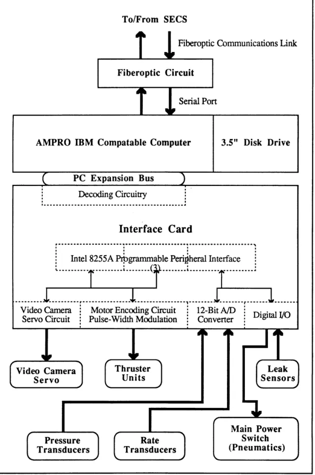
For onboard control, an IBM-PC-compatible AMPRO computer board was installed. This was an 8088 equivalent processor running at 7.16MHz with a total of 512K RAM. A 3.5" floppy disk drive attached to the processor facilitated program portability and decreased the software development time. The presence of a fully operational onboard computer made the programming and debugging process much simpler. The software was programmed in a high level language (C). The only additional systems necessary were the I/O expansion ports, an A/D converter, and the specialized circuitry necessary to command the thrusters. Figure 2.2.2 shows the structure and flow of the onboard processor system (for detailed diagrams of the circuits refer to the ASTRO Guide to Operations and Systems [2]). A fiberoptic communications link for transmitting signal commands to and from the surface was chosen to ensure a clear signal (no noise or voltage drop like that associated with a long, approximately 200 feet, wire cable). The fiberoptic cable was also very light weight, reducing the amount of cable drag on the teleoperator. The communications link operated at 9600 baud, limited by the onboard computer. The fiberoptic circuitry converted the light signal to one compatible with the AMPRO/PC RS232 serial port. Additional electronics were mounted on the interface card. Communications between the AMPRO board and the additional circuitry were carried out via the PC expansion bus and Intel Programmable Peripheral Interface chips (8255). Pressure and rate transducer data was acquired through a 12-bit analog to digital converter. Pulse width modulated thruster commands were generated on the interface card and sent to each thruster with a direction command (forward or reverse). The circuitry at each thruster was responsible for amplifying the command and switching the thruster on and off. The light aperture on the
To/From
T
SECS
J
Fiberoptic Communications Link
Fiberoptic CircuitT
I
Serial PortAMPRO IBM Compatable Computer 3.5" Disk Drive
PC Expansion Bus Video Camera Servo Pressure Rate Transducers Transducers Main Power Switch (Pneumatics)
Figure 2.2.2 ASTRO Onboard Processor System
Decoding Circuitry
... ... ... ...
Interface Card
p . .. - ... a...I
Intel 8255A Prbgrammable Peripheral Interface
I...
...
. ... ...
,-
S... ... ..
---...
...
----
...
Video Camera
:
Motor Encoding Circuit
12-Bit
A/D
Servo Circuit
:
Pulse-Width Modulation
i
Converter
Digital
I/O
W -4
Thruster
UnitsLi
J I L Fvideo camera was adjusted by an actuator servo. The servo was controlled by a frequency signal converted from a 4-bit digital command. As can be seen from the diagram, the various components of this system were relatively easy to isolate, thus making the system easy to service and upgrade. Power for the control system (electronics and sensors) was provided by two 12 volt lead acid gel cell batteries. The batteries were used to power the onboard disk drive, the 3-axis rate transducers, and the 8 volt regulator that supplied power to the pressure transducers. The 5 volts necessary for the PC board and the additional circuitry were supplied by a 5 volt linear (3 amp) voltage regulator, which in turn was powered by the 12 volts of control power.
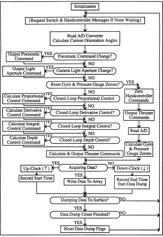
A flowchart of the onboard software is shown in Figure 2.2.3. Communications with the surface via the fiberoptics was interrupt driven. It consisted of a formalized message structure called PIVECS [3] which could be easily reconfigured for different combinations of teleoperators and control stations. The main program served as a shell to call individual functions and to handle data acquisition. These functions were divided up along logical lines of separation and served to increase the clarity of the software and facilitate development and debugging. Appendix A contains a complete listing of the onboard software.
Read A/D Converter
Calculate Current Orientation Angles
Calculate Proportional Control Command
Calculate Depth Control Command
Record End Time Start Data Dump
Figure 2.2.3 Flowchart of ASTRO Onboard Software
|
I x
Translational Rotational
Hand Controller Hand Controller
N IBM Keyboard
Figure 2.3.1 Secondary Electronic Control Station (SECS) 2.3 Secondary Electronic Control Station - SECS
SECS is shown in Figure 2.3.1. It was not designed to be a final configuration, human-factored control station. Rather, it was built with the bare necessities of computers, hand controllers, and switches for running ASTRO and acquiring data. It has proved to be adequate for the job, and has provided insight into the basic necessities and configurations for future control stations.
SECS consists of an IBM personal computer, a color video monitor, two three degree-of-freedom hand controllers, and eight switches. The video monitor was directly linked to the underwater video camera mounted on the front of ASTRO, and provided the operator with a view of the area in front of ASTRO. This view provided visual cues regarding teleoperator orientation and rotation, using such details as the lines in the pool and stationary objects. The two hand controllers were used for specifying XYZ translation (left hand controller) and RPY (roll, pitch, yaw) rotation (right hand controller). The hand controllers acted like potentiometers, with the resistance in each direction of movement (left/right, up/down, and twist) proportional to displacement from the center (zero) position. This resistance was transformed into a voltage, amplified, and read into the computer through an analog to digital (A/D) converter. The eight switches were used to control various functions including main power, proportional, derivative, and integral control, pressure and rate transducer zero resets, and data acquisition. The switch value
(on/off) was read directly into the personal computer. The system diagram is shown in Figure 2.3.2.
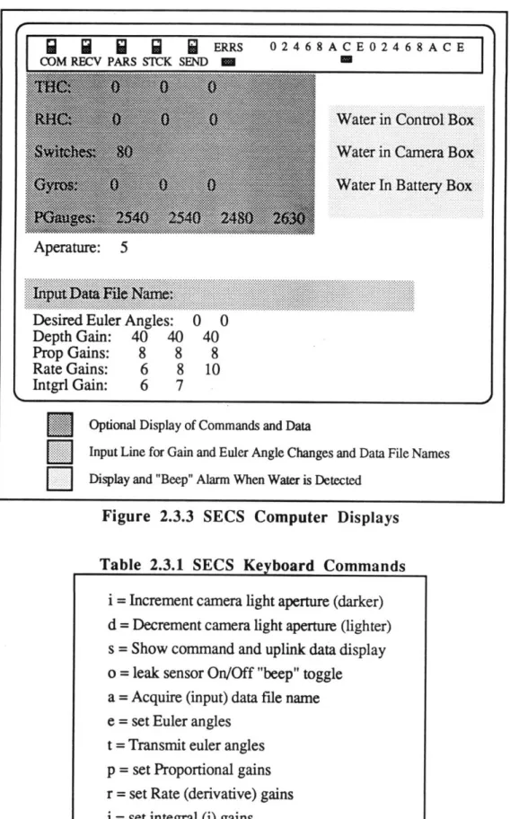
The software on the personal computer was used to acquire commands and to send control station information to the teleoperator. It was also used to provide the operator with teleoperator system command and status displays. A listing of the control station software is contained in Appendix B. Figure 2.3.3 shows the displays and their locations. These displayed parameters included information on leaks and whether they were in the control, camera, or battery boxes, the status of data being received, the light aperture command for the video camera, the proportional, derivative, integral, and depth gains, and the current data file name. Optionally displayed were the hand controller and switch commands, and the pressure and rate transducer uplink data. These optional displays were automatically turned off during data acquisition to increase the speed of the system. The personal computer keyboard was used to set new gains and orientation angles, to turn on and off the optional display and leak alarm, to control the light aperture of the camera, and to signal data acquisition and input data file names. Table 2.3.1 lists these keyboard commands. The monitor cable for the onboard computer was used during testing so that the state of the communications link between the two computers was monitored.
To/From ASTRO
T
Fiberoptic
Communications Link
Fiberoptic Circuit
T I
Serial PortIBM Personal Computer
PC Expansion Bus
Keyboard Input Signals
(By Operator)
Keyboard
Decoding Circuitry
...
a.
... ,...
....
....
Interface Card (PC Expansion Board)
Intel 8255A Programmable Peripheral Interface (1) 1
1rJ
T
SECS Control Panel Switches (8) External Amplifier
Translational Rotational
Hand Controller Hand Controller
Figure 2.3.2 SECS System Block Diagram External Expansion Board
8-Bit A/D Converter
I
Decoding Circuitry
dg
SQ
j j 1 ERRS 02468ACE02468ACE COM RECV PARS STCK SEND MDesired Euler Angles: 0 0
Rate Gains: Intgrl Gain: 6 6 7Control 8 10 B
Input and Euler Angle Changes and Data File N Camera Bos
Display and "Beep" Alarm When Water is DetectedBox
:-1X-:-.*
.
.
..
...
M
.2
.. .
Figure 2.3.3 SECS Computer Displays
Desired Euler Angles: Keyboard Commands
Depth Gain: 40 40 40
Prop Gains: 8 8 8
Rate Gains: 6 8 10
Intgrl Gain: 6 7
E
Optional Display of Commands and Data[
Input Line for Gain and Euler Angle Changes and Data File Names[Z
Display and "Beep" Alarm When Water is DetectedFigure 2.3.3 SECS Computer Displays
Table 2.3.1 SECS Keyboard Commands
i = Increment camera light aperture (darker) d = Decrement camera light aperture (lighter) s = Show command and uplink data display o = leak sensor On/Off "beep" toggle
a = Acquire (input) data file name e = set Euler angles
t = Transmit euler angles p = set Proportional gains
r = set Rate (derivative) gains j = set integral (j) gains
Figure 3.0.1 Pool and Teleoperator Coordinate Systems
3,0 Theory
The purpose of the closed-loop attitude controller was to accurately maintain a desired orientation in inertial roll and pitch and to hold the rate of rotation to zero when no rotation command was given. Because there was no way to measure the yaw orientation
A
angle, the only direct control of rotations about the teleoperator's z axis consisted of rate feedback from angular rate sensors to prevent excessive yaw rotation. Figure 3.0.1 shows the definition of the robot axis and the related rotation angles. A proportional depth controller was also implemented to regulate the teleoperator's depth.
3.1 Theoretical PID Controller
A block diagram of the teleoperator system with a PID attitude controller is shown in Figure 3.1.1. The difficulty in implementing this attitude controller arose from the nonlinear components of the system. These components included the water drag on the outside of the teleoperator, and the applied moments due to the offset of the thrust vectors from the center of mass of the teleoperator. Another nonlinear component was contributed by the motion of the water inside of the teleoperator. All of these nonlinear effects were difficult to quantify. The decision was made to apply a PID type of attitude controller to the teleoperator. However, instead of basing it on the nonlinear equations of motion, an
T = Non-linear Thrust Coupling
D = Non-Linear Water Drag
M = Non-linear Effect of Water Motion Inside the Teleoperator 0 = Orientation State Vector
Figure 3.1.1 PID Block Diagram for the Teleoperator System
equivalent angle-axis representation of the system was used. The basic premise of this system was that a single rotation angle Oe about a calculated axis
f
could be used to correct the orientation error. The details of this representation are discussed in the next section. Implementation of this system was much simpler and reduced the amount and complexity of the calculations involved. The success of this approach was, however, predicated on the assumption that the linearized controller could overcome the disturbance effects of the nonlinear components. This representation also encouraged thruster efficiency because the correction commands worked together to apply a net correction torque. Efficiency was desired to reduce the amount of power used and to extend the total flight time. The data used to calculate the error angle was supplied by the pressure transducers. The derivative term of the controller was based on the data provided by the 3-axis rate transducers. This system was implemented on ASTRO to prove the feasibility of this type of controller. The gains for each of the proportional, derivative, and integral components were set heuristically.To simplify implementation on the teleoperator thruster systems, it was assumed that the desired correctional torque value was proportional to the torque produced by the discrete thruster commands. An arbitrary scaling factor (kscale) was used to move the controller gains into the integer region. The best gains were chosen after experimentation and data analysis. It was also anticipated that the gains might be different for each axis because of the difference in number and efficiency of thrusters mounted parallel to each axis, and of the hydrodynamics of the teleoperator.
3.2 Equivalent Angle-Axis
The underlying idea of the equivalent angle-axis representation of the system, was that a single rotation of magnitude Oe about a calculated unit vector tf could achieve the desired orientation. To build up the angle-axis representation, rotation matrices were first defined. A rotation matrix relates the three principal axes of a system to another set of principal axes in terms of trigonometric functions of the rotation angle between the two. A
rotation matrix can be written for a single rotation, or combined by multiplication to represent multiple rotations [4].
Successive rotations about non-fixed axes are called body axes rotations. Specific combinations of three of these rotations are called Euler angles. One typical set of Euler
angles consists of ordered rotations about the z, y, and x axes. These are called ZYX
Euler angles. The order of the rotations is very important to avoid singularities. The ZYX Euler angles were chosen to be implemented in the controller. A commonly used notation for expressing individual rotations is ROT(axis,angle). Thus the combined ZYX Euler angle rotation matrix can be expressed as
Rotation Matrix = R = ROTr(,a)ROT(y,B)ROT(x,Y) (1)
Note that the order of matrix multiplication occurs in the same order as the "rotations". The complete matrix is
cosa*cosl cosa*sinp3*sinY-sina*cosY cosa*sinp*cosY+sina*sinY
R = sina*cos[ sina*sin *sinY+cosa*cosY sina*sinp*cosY-cosasinY (2)
-sinp
-cosp*sinY
cosp*cosY
Since the yaw rotation angle a could not be measured, as previously discussed, it was set to zero. This simplifies the above rotation matrix to
cos3
sin3*sinY
sino*cosY
R 0 cosy -sinY (3)
-sino -cos3*sinY cosp*cosY
In order to use the equivalent angle-axis representation of the system, the current and desired orientation angles needed to be determined. For the purpose of the experiment, the desired angles were entered into the system via the control station. The current orientation angles were calculated from the data provided by the four pressure transducers mounted inside the teleoperator. The locations of the pressure gauges were shown in Figure 2.2.1. The gauges were mounted inside the robot with the pressure measuring ports pointing inward. The distances separating the gauges from each other were essentially the same, approximately 31.5 inches. Gauges 1 and 2 were parallel to the teleoperator's y axis, while gauges 3 and 4 were parallel to the z axis. The line defined by the average of gauges 3 and 4 and the average of gauges 1 and 2 was parallel to the teleoperator's x axis. The roll and pitch orientation angles were calculated in terms of the pressure gauges by using the ZYX Euler angle rotation matrix. Each column of the rotation matrix represented a principal axis in the teleoperator coordinate frame. Each row of the rotation matrix represented a principal axis in the pool coordinate frame. The pressure or depth differences between each of the gauges were related to specific terms of the rotation matrix. The depths measured by the pressure gauges were related to the z component of the pool coordinate frame in the rotation matrix. Therefore, the lines, Apij, defined by the differences between gauges 3 and 4, 1 and 2, and the averages of 3 and 4 and 1 and 2, could be related to the z component of the appropriate body axis. Thus, from the third row of the rotation matrix:
P(r)z = -sinm = C-1 * AP(aver34 -averl2)
P(r)z = cosB * sinY = C- 1 * APl 2 (4)
P~)z = cosB * cosY = C- 1 * Ap34
Since the distances between the gauges were identical, the C-1 values in the equations were equal. To avoid ambiguity, the 8 and Y angles were found by calculating an atan2 value. Equating the y and z equations by the common C-1 value, yields:
I = atan2(Ap1,AP2 34) (5)
The value for B was found by isolating sin8 from the x equation and cos8 from either the z
A
or y equations. This yields:
The use of both of these equations for 8 eliminated problems associated with division by
zero. The values of B and
Y
calculated from current pressure gauge readings represented
the current orientation angles. It should be noted that due to the nature of the calculations,
the roll orientation angles ranged from ±1800 and the pitch angles, which were calculated
as a result of the roll angle, ranged from ±-900.
The next step was to use these angles to calculate a matrix representative of the
rotation away from the desired orientation. If Rdesire
drepresents the desired orientation
matrix and Rcuren
trepresents the teleoperator's current orientation, the correctional matrix
can be expressed as:
Rdesired * Rcorrection = Rcurrent
(7)
Rcorrection = Rdesired- * Rcurren
t= Rdesired
T* Rcurrent
(8)
In general, the transpose of a rotation matrix is equivalent to the inverse of the rotation
matrix because the matrices are orthonormal. Appendix C contains the matrix calculations
that result in the correctional matrix, Rcorrection, as a function of the desired orientation
angles Ydesired and Bdesire
dand the current angles Ycurren
tand Acurren
t.Shorthand notations
of these will be Yd
,Bd, Y
c, and B
c. The matrix, Rcor~ection (or Rc), looks like
F
c(Bd-c)
sYc*s(8c-Bd)
cYc*s(8cd)
1
Rc = sYd*S(8d-Bc) sTc*sYd*C(BdBc) + CYd*cy, SYd*c'c*C(Bd-Bc) - CYd*sYc (9)
cYd*s(Bd-Bc) cYd*sYc*c(Bda-c) - SYd*CYc cYd*cYc*c(Bd-Bc) + SYd*sYc
where c = cosine and s = sine.
A rotation matrix for a single rotation 0e about an arbitrary axis i is
kx
Rot(,0)
=
Rot( ky ,0)
=
Skx*kx*vO+cO
kx*ky*vO-kzs0
kx*kz*vO+kyso
1
kx*ky*vO+kzso ky*kyv0+c0 ky*kz*vO-kxso (10)
kx*ky*vO-kysO ky*kz*vO+kxsO kz*kz*vO+cO
where c =
cosine, s =
sine, v =
versine
=
1
-
cosO. This matrix would reduce to the more
familiar rotation matrix previously discussed if i were one of the principal axes of the system. The derivation of this matrix can be found in various texts [4,5]. For the purposes of the closed-loop attitude controller, the inverse result was desired, i.e. the rotation angle Oe and axis i needed to be found [5]. If the rotation matrix is rewritten sothat each component is represented by rij, where i is the row number and j is the column number, the matrix looks like
[r1 1 r12 r1 3
Rot(,0) = r21 r2 2 r2 3 (11)
r31 r3 2 r3 3 The rotation angle Oe can then be written as:
0e = acos((rll+ r22 + r33 1.0) / 2.0) (12)
The axis of rotation
f
(a unit vector) is written as:=A ky kz =r11, (2 * sine - r3
(13)
e ) l3 1 (13)
Skz
r21- r12Substituting in actual values for rij from Rcorrec~o n and simplifying, yields
de = acos( (cos(Pd-Pc)*(1.0+cos(Yd-'c)) + cos(Yd-Yc) - 1.0) / 2.0 (14)
S
k x
-sin(Yd
-yc)*(cos(Yd
'•c)+1.0)
(2 * sin0e) -sin( 3d-Ic)*(cosYd + cosYc) (15)
sin(Id- 3c)*(sinYd+sinYc)
Implementing these equations in the attitude controller was fairly straightforward. The simplest way to obtain an output torque was to command a rotation or combination of rotations. Since the onboard software was configured to calculate the thruster commands from a roll, pitch, or yaw rotation command, the attitude controller commands also needed to be put in this form. Each component of the i vector corresponded to one of the teleoperator's principal axes. Thus the desired net rotation Oe about the vector ý was achieved by multiplying the error angle by each weighted component of the
i
vector. This results in rotation commands equal toroll = oe * kx
pitch = ee * ky (16)
yaw = Oe * kz
Although the attitude controller was only attempting to control the roll and pitch orientation angles, the correctional rotation included a yaw component as well. When applied together, these rotational components yielded the single desired correctional rotation.
3.3 PD Controller
The single rotation Oe about the calculated axis
f
that could correct the orientation of
the teleoperator was now known. The next step was to incorporate this knowledge into a
proportional controller.
The proportional control equation is
- = Kp*Kpscale*e (17)
where t is the correctional torque vector, Kp is the diagonal proportional gain matrix, e0 is
the vector of orientation errors, and Kpscale is the diagonal scaling matrix that moves the values in the gain matrix into the integer region. However, instead of simply using the error between the desired and current orientation angles (eO = Odesired " Ocurrent), the correctional angle 0e, weighted by the 9 vector, from the equivalent angle-axis representation was used. The resulting proportional control equation becomes
rI
kx
c
=
p = Kp *Kppscale * e * ky
(18)
ykz
Since simple proportional control is rarely adequate for accurate closed-loop control, a derivative feedback term was also included. The control equation then becomes
ýr
kx
c
=
p = Kp * Kpscale * *
ky I+ Kd * Kdscale*
1
(19)
{y
kz
{,
(where Kd is the diagonal derivative gain matrix and Kdscale is the diagonal scaling matrix
that moves the derivative gains into the integer region. The rate term was determined by the
rate of change of each of the orientation angles because the desired rotation rate was zero.
The rate of change of each of the orientation angles was provided directly by the three-axis
rate transducers installed in the teleoperator.
To simplify the control equations used in the flight software, the gains were chosen
to make the final output of the controller in the same form as regular rotational thruster
commands. This necessitated the use of a dividing factor to restrict the magnitude of the
correctional commands to the range of regular hand controller commands (0 to 15). For
both the proportional and the derivative gains, the maximum allowable error before
correction (the deadband) and the error at which the maximum thrust would be applied
were used to calculate preliminary gain values. The initial deadbands were chosen to be 50
for the proportional term and 5
0/second for the rate feedback term. The errors at which the
maximum correctional thrust would be applied were chosen as
450
and
450/s.
These
values were then adjusted according to the results shown by the data gathered during
testing. Because the yaw orientation could not be directly controlled and a side effect of the closed-loop controller was a small induced yaw rotation, it was anticipated that the derivative gain for the yaw feedback would be significantly higher than the gains for the other two rotations.3.4 PID Controller
Initially, only a PD controller was tested. However, data gathered as a result of testing revealed the presence of a constant offset angle from the desired orientation in each of the axes. A detailed discussion of this data will be presented in the Data and Analysis Section 5.1. Therefore, to improve the system performance, an integral term was added. The equation for the correctional torque then became:
TC = Kp * Kpscale * 0e * ky + Kd * Kdscae * 13 + K * Kiscale* (e *At) (20)
where KI is the diagonal integral gain matrix and Kisade is the diagonal scaling matrix that
moves the integral gains into the integer region. The error was taken to be the difference between the desired orientation angle and the current orientation angle for each axis (e = Odesired -Ocurrent). Because the orientation about the t axis (yaw angle) could not be specified or measured, the integral term was only calculated for the roll and pitch orientations. The change in time, At, is the time between each sample or correctional calculation. This cycle time was measured in the laboratory prior to data acquisition by utilizing the computer system clock. The sample time found for the flight software with complete closed-loop control was 0.40 seconds. For faster program execution and ease of calculation the integral was simplified to a summation. The correctional torque equation then becomes:
c = K * Kpscale * 0e * ky + Kd *Kd dscale * + KI * Kiscale*
_(
* At)k al ~ t=O0
(21) The final values chosen along the diagonals for the scaling factor matrices were 10 for each axis in the proportional term of the controller, 250 for each axis in the derivative term, and 60 for the roll and pitch terms of the integral component. The scaling factor for the yaw term of the integral component was zero because the orientation angles could not be measured.
3.5 Depth Controller
Another observation made while testing the initial PD controller was that the applied correctional torques for the orientations also affected the depth of the teleoperator. In other words, thruster commands intended to correct orientation also had the side effect of propelling the teleoperator up and down in the pool. Since the pressure gauges measured depth, the average of the gauge readings provided an estimate of the depth of the center of the teleoperator. Because the depth of the robot at any given time was the only information available, a simple proportional depth controller was added to the closed-loop system. The proportional control equation is
Fdepth = Kdepth * Kscale * edepth (22)
where the error in depth is the preset or desired average pressure gauge value minus the current average pressure gauge value. The pressure gauge values were used in the integer (bit) format rather than the depth format (floating point) to simplify calculations and decrease processing time.
The z-axis of the teleoperator did not always coincide with the z-axis of the pool. Thus, a rotation matrix reflecting the current orientation with respect to the pool coordinate system, specifically the z (pool) axis, was needed. This matrix is the same as the rotation matrix originally calculated for the attitude equations, and is restated here as
cosj
sinp*sinY sint*cosY
0 cosY -sinY
-sino -cosp*sinY cosp*cosY
-The components of this matrix that show the relationship between the teleoperator's axes and the pool's z axis are the components in the third row. Thus the vector that is needed is
-sin8
Zpool = cos*sinY (23)
cos8*cosY
The implemented depth controller is therefore
Fx -sinS
Fdepth = Fy =Kdept
h
* Kscale* edept
h
* cos*sin
(24)
Fz cosB*cosY
where Fdepth is the force vector required to correct the depth error, Kdepth is the diagonal proportional depth gain matrix, Kscale is the diagonal scaling factor matrix used to move the
depth gain into the integer region (the values along the diagonal are equal to 75), edepth is
the error in depth, and the components of the ýPo vector are used to weight the error and thus the correctional force.
The initial gains for the depth controller were chosen so that the deadband was approximately 0.25 feet and the depth error that triggered the maximum thrust value for correction was approximately 3.0 feet. It was anticipated that these values would change after data was taken and analyzed.
4.0 Test Set-IU
The equipment used in the experiment were SECS and ASTRO. Communication between the control station and the teleoperator was performed via a fiberoptic link. The communications software shell, PIVECS, was used to transfer information up and down the link. Color video signals were sent to the monitor on SECS via another cable. The overall test set-up is shown in Figure 4.0.1.
In order to obtain accurate sensor values the pressure and rate transducers first needed to be zeroed. This was done by taking a set of readings that were used as adjustment values for the data taken during testing. These readings were taken on the pool deck before the teleoperator was put into the water and between tests when it was underwater. Zeroing the values while in the water required holding the robot as still as possible for the rate readings, and leveling each pressure gauge with respect to the others for each gauge reading. Small levels were placed on three faces of the teleoperator (the top, port side, and 450 between them) to assist with this. The information provided by the rate sensors and pressure gauges were read into the onboard computer through a 12-bit analog-to-digital converter. These numbers were then converted into a usable form and utilized in the closed-loop controller calculations. The thruster commands were sent out of the onboard computer in the form of a 4-bit digital command. Interface circuitry converted those commands into a pulse-width modulated signal which was then sent to the appropriate thruster. Amplification and current switching was performed in the power modules attached to each thruster unit.
The closed-loop controller ran directly in the onboard software. The calculated contribution of each part of the attitude controller was added to the appropriate rotational thruster command. The regular hand controller commands were disabled for the bulk of the experiments in order to speed up the system execution time. The depth controller contributions were added to the thruster x, y, and z translation commands. The output command magnitude was limited to the maximum value of 15.
During the data run, all of the raw (12-bit) pressure and rate transducer values were stored on ASTRO in a large array (1000 samples). Data was continuously stored until the data acquisition was completed. At this time, the thrusters on ASTRO were disabled (main power was turned off) and the number of samples was sent to the surface computer. The pressure and rate transducer values were then sent to the computer on the surface in the same manner as regular communications, except that all of the other transmissions were overridden. When all the data was received the control station computer wrote the data into
I~
0E
the previously specified data file along with the number of samples and the values of the desired orientation angles. The time between samples, or cycle time, on ASTRO was measured in previous experiments as 0.40 seconds. This measurement was made by using the system clock to calculate the total time passed during a data run. The length of time was then divided by the number of samples taken during the run.
5.0 Data and Analysis
As with any controller, the desired system results should demonstrate a stable controller that is robust and can compensate for reasonable outside disturbances. The disturbances tested in the research were approximately the maximum disturbances that could be reasonably expected in this type of experimental research (i.e. those caused by collision with the pool wall, another teleoperator, or a diver). Other desired features were a quick response time, low overshoot, small or non-existent steady-state error, and no limit cycling. In addition, the minimization of uncontrolled yaw rotation, despite the fact that it could not be directly measured, was also desired.
Data files were obtained for straight regulation of (00,00), (450,00), and (00,450)
orientation angles, where the first number was the roll angle and the second was the pitch angle. Each of these is pictured in Figure 5.0.1. Responses to step inputs and pseudo-random disturbances, as well as attempts at free-flight were also obtained. The step inputs
were generated by changing the desired orientation angles. Disturbances were generated by
underwater divers applying a torque to each axis singly and in combination. Disturbance
files were taken by allowing the teleoperator 45 seconds to regulate (determined from
previous data to be sufficient), imparting a disturbance, and then allowing approximately
60 to 90 seconds for the system to return to equilibrium. Tests to demonstrate the overall
accuracy of the system were performed by specifying a specific orientation and then
attempting to fly the teleoperator along a straight line translation.
The performance of the depth controller was tested by setting the teleoperator in
different attitudes and applying a depth disturbance in either direction. The depth response was also evaluated based on the data from the attitude regulation, step response, and disturbance files. The depth disturbance files contained disturbances in both directions (the force applied driving the robot deeper, allowing 60 seconds or more to settle, and another force applied driving the robot shallower). The data obtained in the experiments are presented below.A
y= 450
(b) (450,00) Orientation
(c) (00,450) Orientation
Figure 5.0.1 Teleoperator Orientations
A Y ASTRO A ASTRO x pool X ASTRO (a) (00,00) Orientation A Z A z poo ASTRO A Y pool A A Z pool ASTRO