Publisher’s version / Version de l'éditeur:
Canadian Journal of Civil Engineering, 7, 3, pp. 551-558, 1980-09
READ THESE TERMS AND CONDITIONS CAREFULLY BEFORE USING THIS WEBSITE. https://nrc-publications.canada.ca/eng/copyright
Vous avez des questions? Nous pouvons vous aider. Pour communiquer directement avec un auteur, consultez la première page de la revue dans laquelle son article a été publié afin de trouver ses coordonnées. Si vous n’arrivez pas à les repérer, communiquez avec nous à PublicationsArchive-ArchivesPublications@nrc-cnrc.gc.ca.
Questions? Contact the NRC Publications Archive team at
PublicationsArchive-ArchivesPublications@nrc-cnrc.gc.ca. If you wish to email the authors directly, please see the first page of the publication for their contact information.
NRC Publications Archive
Archives des publications du CNRC
This publication could be one of several versions: author’s original, accepted manuscript or the publisher’s version. / La version de cette publication peut être l’une des suivantes : la version prépublication de l’auteur, la version acceptée du manuscrit ou la version de l’éditeur.
Access and use of this website and the material on it are subject to the Terms and Conditions set forth at
New facility to determine fire resistance of columns
Lie, T. T.
https://publications-cnrc.canada.ca/fra/droits
L’accès à ce site Web et l’utilisation de son contenu sont assujettis aux conditions présentées dans le site LISEZ CES CONDITIONS ATTENTIVEMENT AVANT D’UTILISER CE SITE WEB.
NRC Publications Record / Notice d'Archives des publications de CNRC:
https://nrc-publications.canada.ca/eng/view/object/?id=be046036-ab1d-494d-b519-0a2bbc7a2613 https://publications-cnrc.canada.ca/fra/voir/objet/?id=be046036-ab1d-494d-b519-0a2bbc7a2613S e r
Nat~onal
Research
Conseil national
TH1
I
+
Council Canada
de recherche Canada
N21d
no.
914
cop. 2
NEW FACILITY TO DETERMINE FIRE RESISTANCE
OF COLUMNS
by T.
T.
LieReprinted from
Canadian Journal of Civil Engineering Vol.
7,
No. 3, September 1980 pp. 551-558DBR Paper No. 914
Division of Building Research
Price $1.00
ANALYZED
N R C-
ClSTl BLDG. RES.L I B R
k 2 Y OTTAWA NRCC 18423This publication is being distributed by the Division of Building Research of the National Research Council of Canada. It should not be reproduced in whole or in part without permis- sion of the original publisher. The Division would be glad to be of assistance in obtaining such permission.
Publications of the Division may be obtained by mailing the appropriate remittance (a Bank, Express, or Post Office Money Order, or a cheque, made payable to the Receiver General of Canada, credit NRC) to the National Research Council of Canada, Ottawa. KIA 0R6. Stamps are not acceptable.
A list of all publications of the Division is available and may be
obtained from the Publications Section, Division of Building Research, National Research Council of Canada, Ottawa.
New facility to determine fire resistance of columns
I
T. T. LIE
Fire Research Section, Division of Building Research, National Research Council of Canada, Ottawa, Ont., Canada KIA OR6
Received February 11, 1980
Accepted March 27, 1980
The new Division of Building Research (DBR) column testing furnace is described and an
d
outline given of the proposed studies that this facility makes possible.Le four de mise a I'essai des poteaux de la Division des recherches en bkiment (DRB) est decrit
J
et les differentes etudes que cette installation peut permettre sont enumirees.
Can. J. Civ. Eng., 7,551-558 (1980)
03 15- 1468/80/03055 1-08$01.00/0
@I980 National Research Council of Canada/Conseil national de recherches du Canada
552 CAN. J. CIV. E LNG. VOL. 7, 1980
Introduction
One of the safety requirements for buildings today is the provision of appropriate fire resistance. Until fairly recently, the fire resistance of building com- ponents could only be determined by costly and time-consuming tests. Now it can be determined by calculation, thanks to the development of mathe- matical models. Because these models only partially represent reality, however, their validity must be verified.
A versatile column testing furnace has recently been installed at the Division of Building Research of the National Research Council of Canada. The new facility will enable the Division to test the validity of mathematical models to predict fire resistance, and to obtain a better understanding of the many problems for which there are yet no theoretical solutions. Although designed for research purposes, the furnace is also capable of performing standard tests on specimens in accordance with most international standards.
Calculation Procedure
Predicting the fire behaviour of structural members involves the specification of fire temperatures and the calculation of temperatures, deformations, and strength of structural members. Because all these quantities vary with time the calculation procedure is complex, but it has been simplified by the develop- ment of numerical calculation techniques and the use of high-speed computers. The various steps in calculating the fire resistance of a member and deter- mining the appropriate protection are shown in Fig. 1.
Fire Load
First is the determination of the fire load, i.e., the combustible contents, which should form the basis for the fire resistance design of a building. Several surveys have been carried out recently to obtain information on fire loads in buildings (Bryl et al.
1974; National Academy of Sciences 1977). Fire Temperature
Assuming that the design fire load is known, the next step is to determine time-dependence of the fire temperature. Calculation of the fire temperature course of compartment fires has been the subject of several studies (Kawagoe and Sekine 1963; odeen 1963 ; Magnusson and Thelandersson 1970; Tsuchiya and Sumi 1971; Harmathy 1972). The fire tempera- ture course can be determined from a heat balance for the compartment, taking into account the heat produced and the heat losses to walls and openings. The most important factors are fire load and the dimensions of the openings through which air,
I
D E T E R M I N A T I O N O F D E S I G N F I R E L O A DI
C A L C U L A T I O N O F F l R E T E M P E R A T U R E C U R V E P R O P O S E D P R O T E C T I O Nr+=7
1 C A L C U L A T I O N O F T E M P E R A T U R E S O F S T R U C T U R E rl, C A L C U L A T I O N OF S T R E N G T H O F S T R U C T U R E D U R I N G F l R E M O D I F Y P R O T E C T I O NFro. 1. Calculation procedure for fire-resistant design.
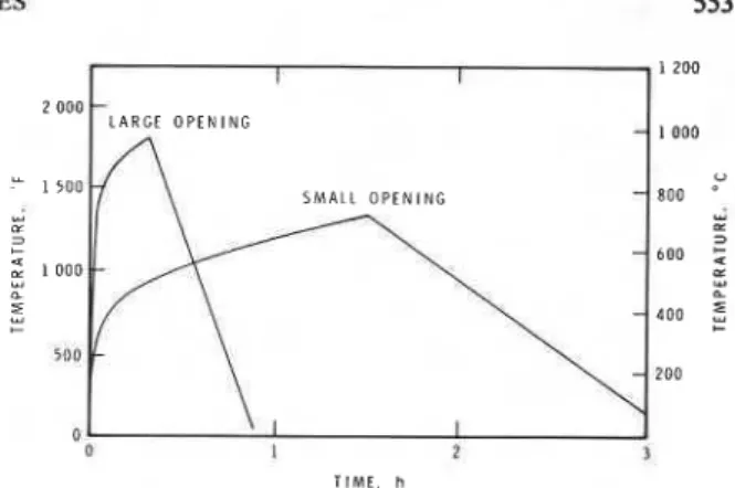
necessary for combustion of the fire load, can enter. How fire load affects fire temperature is shown in Fig. 2, the influence of openings in Fig. 3. Fire load determines the duration of the fire, whereas the openings influence both intensity and duration. The calculated fire temperature course or, eventually, a standard fire temperature curve is used as exposure
temperatures for the calculation of the temperatures I
in structural members. Temperature of Members
Temperatures of fire-exposed structural members 4
can be calculated; the most common procedures are the finite difference and finite element methods. In these, the dependence of material properties on temperature is taken into account and, in some cases, a high accuracy can be obtained. For example, the accuracy with which temperatures in protected steel can be predicted is better than 1% if the material properties of the protection are known precisely (Lie 1977). In practice this is usually not the case, but an accuracy of 15-20% is possible, which in the field of fire is regarded as fairly accurate.
TIME, h T I M E , h FIG. 2. Influence of fire load on fire temperature course.
obtain for concrete the same accuracy as for steel, it * is in fact more difficult to predict concrete tempera- tures. The main reason is that the thermal properties of concrete depend strongly on the properties of the aggregate, which may vary over a wide range and are difficult to determine accurately. In addition, moisture in concrete will have considerable influence on its internal temperatures.
Strength of Members
When the temperature rises in fire-exposed members, their strength lessens. If the fire load is sufficient and the duration of the fire long enough, a stage will be reached at which the strength of the member will no longer be adequate to support the structural load. The fire load that is just sufficient to reduce the strength to this critical point is defined as the critical fire load. The aim is to make the critical fire load for a member sufficiently high to allow it to withstand the burn-out of the design fire load. In general, this can be achieved by selecting for the member appropriate protective materials of adequate thickness and appropriate dimensions.
Test Furnace
,
The test furnace was designed so that it could produce the conditions to which a member might be exposed during a fire, such as fire temperatures, structural loads, and heat transfer. It consists of a steel framework supported by four columns with the furnace chamber inside the framework (Fig. 4; Table 1 gives details of furnace characteristics). Loading Device
Three hydraulic jacks produce forces along the three principal axes. The jack acting along the axis of the test column is designed for a maximum load of 2200 kips (9790
kN).
This capacity is sufficient to subject concrete columns of approximately 30 in. x30 in. (760 mm x 760 mm) to their design load. This jack can also be used to restrain the thermal
FIG. 3. Influence of openings on fire temperature course.
expansion of a column and thus simulate the con- ditions in fires where column expansion is restrained by upper floors. The other two jacks exert lateral forces at the top of the column, to simulate the forces and displacements due to floor expansion during a fire. Loads and movements of the jacks can be con- trolled manually or by computer, and can be pro- grammed to follow a predetermined course, making it possible to simulate a wide range of practical conditions.
Furnace Chamber
There are 32 propane gas burners in the furnace chamber arranged in eight columns of burners con- taining four burners each. The total capacity is 16 000 000 Btu/h (4700 kW), which should be sufficient to simulate any fire severity encountered in practice.
The Dressure in the furnace chamber is controlled automatically. It is usually set somewhat lower than atmospheric pressure to avoid a flow of gases from the chamber to outside. If necessary, for example to meet ISO1 standards, the furnace can be run at an overpressure.
It is possible to test both columns and walls with a fire-exposed length of between 10 and 14 ft (3.1 and 4.3 m) in the furnace. Heating can be controlled in such a way that one or more sides of the specimen are exposed to fire.
The furnace chamber, whose floor area is 8 ft 8 in. (2.6 m) square, is made of an insulating material that will produce high heat transfer to the specimen. The roof can move freely upwards and functions as a blow-out panel as a safety measure against explosion. Safety against explosion is provided by various other measures. Before ignition of the pilot burners there is a purge period in which an amount of air about three times the volume of the furnace chamber is blown through it. In each burner there is an ultra-
554 CAN. J. CIV. ENG. VOL. 7, 1980
FIG. 4. Test furnace and specimens. violet sensor that can detect failure of a burner. If
this happens, the gas supply to the column of burners in which the failure occurred will shut off auto- matically. It is possible, however, to restart the burners manually, without purging, provided the furnace temperature has reached a level at which there is no danger of explosion. A temperature of 1000°F (588°C) was selected as being safe. This temperature is usually reached after 5 min in a
standard test. Being able to restart the burners without purging prevents the loss of a test in an advanced stage.
Instrumentation
Furnace temperatures are measured with the aid of Chromel-Alumel thermocouples installed 1 ft
(0.3 m) from the test specimen at various heights.
NOTES
TABLE 1. Furnace characteristics Loading device
Capacity axial load [kips (kN)] 2200 (9790)
Capacity lateral load (x-axis) [kips (kN)] 70 (310)
Capacity lateral load (y-axis) [kips (kN)] 25 (110)
Maximum movement of axial jack [in. (mm)] 12 (305)
Maximum movement of lateral jacks [in. (mm)] 6 (152)
Maximum speed of jacks [in./min (mm/rnin)] 3 (76)
Accuracy of controlling and measuring loads
(% at low loads) Approx.
+
5Accuracy of measuring displacements [in. (mm)] kO.004 (0.1) Furnace chamber
I Inner height of chamber [ft (m)] Up to 14 (4.3)
Floor area [in. (m)] 104 (2.6)
Capacity of 32 burners [Btu/h (kW)] 16 000 000 (4700)
Temperature uniformity (% deviation from
average temperature after 5 min) Less than 2
Pressure in chamber at 9 ft (2.7 m) height Adjustable between
-
0.2 and +0.2in. (-5and + 5 m m ) H 2 0 Properties of material of floor, ceiling, and doors (ceramic blanket)At 932°F (773 K )
Density [Ib/ft3 (kg/m3)] 6 (96)
Specific heat [Btu/lb. "F (J/kg.K)] 0.26 (1 090) Thermal conductivity [Btu/ft .h. "F (W/m .K)] 0.007 (0.12) At 2000°F (1352 K )
Density [Ib/ft3 (kg/m3)] 6 (96)
Specific heat [Btu/lb. "F (J/kg.K)] 0.27 (1130)
Thermal conductivity [Btu/ft
.
h.
"F (W/m .K)] 0.24 (0.42) Properties of material of walls (insulating fire brick) At 932'F (773 K)Density [Ib/ft3 (kg/m3)] 45 (720)
Specific heat [Btu/lb. OF (J/kg. K)] 0.24 (1000)
Thermal conductivity [Btu/ft
.
h "F (W/m .K)] 0.15 (0.26) At 2000°F (1352 K)Density [lb/ft3 (kg/m3)] 45 (720)
Specific heat [Btu/Ib.OF (J/kg.K)] 0.31 (1300)
Thermal conductivity [Btu/ft h . "F (W/m.K)] 0.28 (0.48)
other every 2 ft (0.6 m) along the height of the furnace chamber, starting from the floor. The tem- peratures measured by the thermocouples are averaged automatically and the average temperature used as the criterion for controlling the furnace temperature.
As every burner can be adjusted individually a high temperature uniformity can be obtained. At present the uniformity is such that after 5 min the deviation of temperature at the various measuring points from the average furnace temperature is less than 2%.
Triaxial loads are measured by pressure trans- ducers that supply an electrical signal to recorders.
Axial deformations of test specimens and lateral displacements at the top of the specimen are measured with linear potentiometers. In testing restrained specimens, the deformations of the steel framework of the furnace are measured with strain gauges.
All electrical signals, i.e., those from temperature, load, and deformation sensors, can be used to
control these quantities. A computerized control and data acquisition system is usedfor this purpose and for measuring the important variables that deter- mine the performance of test specimens during exposure to fire.
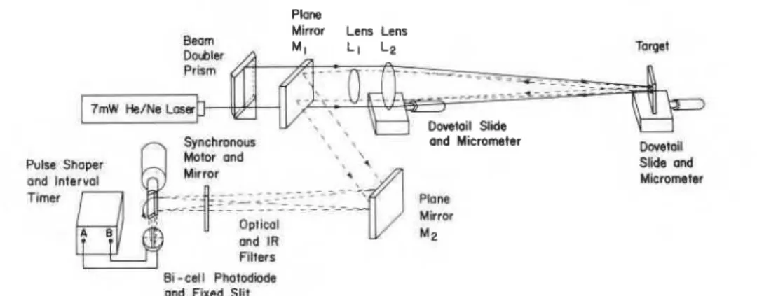
A problem of long standing is how to measure accurately the deflection of a specimen in a furnace: the temperature is too high to use conventional methods. A method that has been developed recently by the Division of Physics, NRCC, is used to measure deflections in this furnace. In this method (Chapman and Green 1977), whose general purpose is to measure movements in a hostile environment (Fig. 5), a laser beam is split into two beams with the aid of a beam doubler. The beams are focused on a target, in this case the centre of the column. Thus two spots are formed on the target. If the target moves, the distance between the two spots changes. With the aid of lenses and mirrors an image is formed of the two spots. The image of each point is reflected,
CAN. J. CIV. ENG. VOL. 7, 1980 Plane
Mirror Lens Lens
Bwm
t]&ler A M' L ' Lz
and Micrometer me.--
Sychmnw5 1 7 Motor m d . \ -1UII Mirror , % Snde m
...
" t 4 ..i. ----a- and lnta, f rmer a d IR M Z-
W-cell P b W iand Firnd Slit
FIG. 5. Device for measuring deflections (Division of Physics, National Research Council of Canada). TABLE 2. Information on test columns
Number
of Cross section, Moisture
columns [in. x in. (mm x mm)] Load condition Aggregate Purpose of test 3 12 x 12 0 Atmospheric Siliceous Repeatability
(305 x 305)
1 8 x 8 0 Dry Siliceous Heat transfer
(203 x 203)
1 12 x 12 0 ~ i y Siliceous Heat transfer (305 x 305)
1 16 x 16 0 Dry Siliceous Heat transfer (406 x 406)
1 12 x 12 Design Dry Siliceous Loaded model (305 x 305) load
2 12 x 12 To be Atmospheric Siliceous Influence load (305 x 305) selected
1 12 x 12 0 Atmospheric Carbonate Influence aggregate (305 x 305)
2 12 x 12 To be Atmospheric Carbonate Influence aggregate (305 x 305) selected
NOTE: Column lengths are all 12.5 ft (3.8 m).
one after the other, on a photocell with the aid of a rotating mirror. In this way, pulses are generated by the cell. Because the time interval between two pulses is proportional to the displacement of the column, the deflection of the column can be determined by measuring this time interval.
The deflections of a column are measured along the two orthogonal axes perpendicular to the column axis. Tests in an existing furnace show that the device is capable of measuring displacements with an accuracy of k0.004 in. (0.1 mm) at a distance of 61 in. (1550 mm).
Test Program
Concrete Columns
The first series of columns intended for testing, as a part of a joint study, are reinforced concrete columns constructed by the Portland Cement Association. Mathematical models for calculating
the temperature distribution in square columns and their strength during exposure to fire were developed a few years ago (Lie and Allen 1972; Allen and Lie
1974). By subjecting the columns to the fire con-
'
ditions and loads assumed in the models it will bepossible to verify the validity of these models.
Figure 4 shows one column installed in the furnace , and two, awaiting tests, on the right. In total 12 columns were constructed for the first series of tests; information on these columns is given in Table 2. Three columns of 12 in. x 12 in. (305 mm x 305 mm) cross section were constructed to examine the repeatability of the tests. Three columns 8 in. x 8 in.
(203
mm
x 203 mm), 12 in. x 12 in. (305 mm x305
mm),
and 16 in, x 16 in. (406mm
x 406 mm),will be tested unloaded to verify the heat transfer model. One column will be tested under the design load to compare the calculated with measured fire resistance. Two columns will be tested under lower
NOTES 557
-
CALCULATED 1 2 0 0 Y-
1auu u' 30 6 0 TIME, m l nFIG. 6. Temperatures at various depths along centre line in 12 in. x 12 in. (305 mm x 305 mm) column as a function of time.
load to obtain information on the influence of over- design. The other columns were made with carbonate aggregate to determine the influence of the aggregate on the fire resistance of the columns.
Tests on a second series are planned. The columns will be larger and the influence of the steel reinforce- ment cover thickness on the fire resistance of the column will be examined. It is also intended to test more columns made with carbonate aggregate, to see if they have a higher fire resistance than those made with siliceous aggregate.
Figure 6 shows the results of the first test of the series. This was carried out on a column of 12 in. x
12 in. (305 mm x 305 mm) to examine the tem- perature distribution in the column. In Fig. 6 calculated temperatures are compared with tem- peratures measured at the following depths: 1, 23, and 6 in. (25, 63, and 152 mm). Calculated tempera- tures are higher than most measured temperatures, but the differences are relatively small. The results indicate that the heat transfer model is reasonably ,
accurate, although it is somewhat conservative. More tests under various conditions must be carried out, however, to establish a mathematical model that can be used with confidence for such calculations.
Steel
One of the mathematical models that has been validated is for heat transfer in protected steel (Lie 1977). Often a critical temperature of the steel can be specified for use as a criterion of failure. In this case the calculation of failure can be reduced to the calculation of the temperature of the steel. North American standards, for example, assume an average steel temperature of 1000°F (538°C) as the failure
temperature of steel columns. Although accurate prediction of steel temperatures is possible this assumption creates an uncertainty in the prediction of failure. It is probable that factors such as load and slenderness of the column play an important role in determining the failure temperature. With the aid of the new column furnace it will be possible to investigate this.
Another project now under study is the fire resist- ance of concrete-filled steel columns. These columfis have several advantages, one of which is that concrete filling can be provided at a lower cost than conventional protection. In addition, by designing the column so that the steel carries the load at room temperature and the concrete carries it at fire tem- peratures when the steel has lost most of its strength, a fire resistance of more than 2 h can be obtained. This resistance is obtained without added protection; unfilled the fire resistance of the steel would be not more than about 10 min. Another advantage of fire protection by concrete filling is that some floor space is gained because there is no outside protection.
The concrete filling also substantially increases the strength of the column but there must be enough concrete to obtain sufficient fire resistance, which may be more than is needed for structural loads.
The construction of mathematical models for the calculation of the fire resistance of concrete-filled columns is at an advanced stage. It is anticipated that the new column test furnace can soon be used to study the performance of these columns.
Conclusion
Development of numerical techniques and the introduction of powerful computers have accelerated the transition from testing to calculation of fire resistance. Few facilities exist, however, that are capable of producing the conditions necessary to determine the adequacy of the mathematical models used for the prediction of fire resistance. NRCC's Division of Building Research has now installed a versatile testing furnace that can test full-scale columns and walls under various load and fire conditions.
Acknowledgement
Plant Engineering Services of the National Research Council of Canada was responsible for the design and construction of the column furnace. Thanks are due to E. A. Cunningham for his major contribution in accomplishing this work. This paper is a contribution from the Division of Building Research, National Research Council of Canada and is published with the approval of the Director of the Division.
558 CAN. J. CIV. ENG. VOL. 7, 1980
ALLEN, D. E., and LIE, T. T. 1974. Further studies of the fire resistance of reinforced concrete columns. Division of Build- ing Research, National Research Council of Canada, Ottawa, Ont., NRCC 14047.
BRYL, S., DEMOL, L., CZECH, R., and buss^. 1974. Fire loads in office buildings. Fire Safety in Constructional Steelwork, European Convention for Constructional Steelwork, Paris. France.
CHAPMAN, G. D., and GREEN, E. 1977. A non-interferometric optical probe. Review of Scientific Instruments, 45(6), pp.
617-624.
HARMATHY, T. Z. 1972. A new look at compartment fires. Part I and Part 11. Fire Technology, 8(3), pp. 1%-217; 8(4), pp.
326-351.
KAWAGOE, K., and SEKINE. T. I%3. Estimation of fire temper- ature
-
time curve in rooms. Building Research Institute, Ministry of Construction, Tokyo, Japan, BRI Occasional Re- port No. 11.LIE, T. T. 1977. Temperature distributions in fire-exposed building columns. Journal of Heat Transfer, 99(1), pp.
113-1 19.
LIE, T. T., and ALLEN, D. E. 1972. Calculation of the lire
resistance of reinforced concrete columns. Division of Build- ing Research, National Research Council of Canada, Ottawa, G t . , NRCC 12797.
MAGNUSSON. S. E.. and THELANDERSSON, S. 1970. Tempera- ture-time curve; of complete process of fire development. Theoretical study of wood fuel fires in enclosed spaces. Acta Polytechnica Scandinavica, Stockholm, Sweden, Civil En- gineering and Building Construction Series No. 65. NATIONAL ACADEMY OF SCIENCES. 1977. Fire and live loads in
buildings. Committee on Fire and Live Loads in Buildings of the Building Research Advisory Board, National Academy of Sciences, Washington, DC.
ODEEN, K. 1%3. Theoretical study of fire characteristics in enclosed spaces. Division of Building Construction, Royal
Institute of Technology, Stockholm, Sweden, Bulletin 10. I
TSUCHIYA, Y., and SUMI, K. 1971. Computation of the be- haviour of fire in an enclosure. Combustion and Flame, 16, pp.