Publisher’s version / Version de l'éditeur:
Vous avez des questions? Nous pouvons vous aider. Pour communiquer directement avec un auteur, consultez la
première page de la revue dans laquelle son article a été publié afin de trouver ses coordonnées. Si vous n’arrivez pas à les repérer, communiquez avec nous à [email protected].
Questions? Contact the NRC Publications Archive team at
[email protected]. If you wish to email the authors directly, please see the first page of the publication for their contact information.
https://publications-cnrc.canada.ca/fra/droits
L’accès à ce site Web et l’utilisation de son contenu sont assujettis aux conditions présentées dans le site
LISEZ CES CONDITIONS ATTENTIVEMENT AVANT D’UTILISER CE SITE WEB.
Research Paper (National Research Council of Canada. Division of Building
Research); no. DBR-RP-650, 1975-05
READ THESE TERMS AND CONDITIONS CAREFULLY BEFORE USING THIS WEBSITE. https://nrc-publications.canada.ca/eng/copyright
NRC Publications Archive Record / Notice des Archives des publications du CNRC :
https://nrc-publications.canada.ca/eng/view/object/?id=e930bb59-f303-48f2-a734-48e30e320510 https://publications-cnrc.canada.ca/fra/voir/objet/?id=e930bb59-f303-48f2-a734-48e30e320510
NRC Publications Archive
Archives des publications du CNRC
This publication could be one of several versions: author’s original, accepted manuscript or the publisher’s version. / La version de cette publication peut être l’une des suivantes : la version prépublication de l’auteur, la version acceptée du manuscrit ou la version de l’éditeur.
For the publisher’s version, please access the DOI link below./ Pour consulter la version de l’éditeur, utilisez le lien DOI ci-dessous.
https://doi.org/10.4224/40001759
Access and use of this website and the material on it are subject to the Terms and Conditions set forth at
Small-scale fire tests of walls penetrated by telephone cables
S e r T H l
N21r 2
no.
650
NATIONALRESEARCH
COUNCIL OF CANADAc . 2
CONSEIL NATIONAL D E RECHERCHES DU CANADA
BLDG
Small-Scale Fire Tests of Walls
Penetrated by Telephone Cables
by
J .
H. McGuireReprinted from FIRE TECHNOLOGY
Vol. 11, No. 2, May 1975
p. 73-79
Research Paper No. 650
of
theDivision
of
Building ResearchL'ESSAI AU FEU SUR MODELLE REDUIT DES MURS TRAVERSES PAR DES CABLES TELEPHONIQUES
SOMMAIRE
Quatre essais de resistance au feu ont 6th effectu6s sur des modkles reduits de murs travershs par des cgbles t616phoniques. On a adopt6 arbitrairement cornrne critkre de rupture que les temperatures ne devraient pas depasser 1000°F B la surface non exposee du cgble, du manchon ou du mur, et qu'il ne devrait pas se produire d'ouverture superieure
B
0, 1 poa. On conclut que presque toute disposition serait satisfaisante lorsque le four fonctionne sous une pression negative, mais qu'une pression positive exige une mise en place des manchons et un Qtachement soigneux. Une mince t81e d'acier donne les meilleurs manchons dans les essais sous une pressionF I R E TECHNOLOGY
Small-Scale Fire Tests of Walls
Penetrated by Telephone Cables
J. H.
McGUIREDivision of Building Research
National Research Council of Canada
Four small-scale fire-resistance tests have been carried out on walls penetrated by telephone cables. The failure criteria were t h a t temperature should not exceed 1000° F a t the unexposed surfaces of the cable, sleeve or wall, nor should openings greater t h a n 0.1 square inch develop.
w
ALL AND FLOOR specimens are frequently subjected to extensive large-scale fire tests to determine their fire resistance, and it is usually assumed that, in practice, the performance of walls and floors will corre- spond to the specimens tested. Unfortunately, walls are too often weakened by provisions for building services to pass through them. The significance of penetrations is of great interest both to Bell Canada, as it relates to telephone cables, and to the Division of Building Research, National Re- search Council of Canada. A cooperative investigation was, therefore, undertaken of the influence on the fire resistance of a wall of passing telephone cables through it.An important feature of the test work was that much of it involved operating the test furnace a t a substantial positive pressure to represent the undesirable, adverse conditions that could prevail during the course of a fire in a high-rise building (at least five or possibly ten floors high, depend- ing on the severity of local exterior temperatures). During normal use of a high-rise building, it is not customary for excessive pressure differentials to prevail across internal partitions; if they did, conditions could well become untenable as a result of discomfort and difficulties in opening doors.
A
substantial total pressure differential, up to 1-inch WG (water gage) per 300 feet of building height, can exist over the height of a building in midwinter as a result of stack action due to building heating.' The com- ponent pressure differentials, which are directed inward a t the base of the building and outward a t the top, are largely developed across the ex- terior skin of the building because it is the tightest membrane. Only during the course of a fire might these pressure differences be found across the interior partitions bounding the fire region as a result of window breakage.73
Copyright 1975, NATIONAL FIRE PROTECTION ASSOCIATION, 4 7 0 ATLANTIC AVE., BOSTON, MASS. 02210 Printed in U.S.A
74' Fire Technology With substantial window breakage, the pressure in the fire area could approach the exterior pressure; and a t low levels in the buildings, it could be substantially higher than the pressure of the adjacent inside areas.
T E S T F A C I L I T I E S A N D C O N D I T I O N S
The test furnace (Figure 1) was originally designed to be used in in- vestigating the penetration of walls by plastic drain, waste and vent pipes." Figure 2 illustrates the layout and dimensions. Eight gas-fired burners are located in the outer chamber, and their products of combustion pass into the inner chamber and thence to the flue. As the products of combustion from test specimens do not return to the outer chamber, they cannot damage it if they are corrosive.
The flue is directed downwards so that its stack effect creates a positive rather than a negative pressure. To operate the furnace a t negative pressure, the integral flue is connected to a 20-foot-high vertical flue, the stack effect of which can overwhelm that of the downward projecting integral flue.
As illustrated in Figure 2, wall specimens constitute the end closures of the 16-inch-diameter, cylindrical iililer furnace chamber. T h e same wall specimens were used for all four tests. They consisted of 4-inch thicknesses of high-temperature concrete of approximately 58 pounds per cubic foot density. Penetrations through one of the two wall specimens involved 6-inch long, 4%-inch diameter pipe sleeves made of %-inch thick steel; this feature did not, however, substantially influence performance.
The cable samples ranged from a 25-pair, 0.38-inch OD (outside diameter) sheathed in 0.035-inch-thick PVC to a 3000-pair, 3-inch OD cable sheathed in aluminum and steel terneplates and polyethylene jacket. The packing around the cable served as fire-stopping and usually consisted of
Telephone Cables
/ R E F R A C T O R Y F I R E B R I C K S
A I R I N T A K E T E S T W A L L
F R O M O U T E R
1 '
1::
Figure 2. Horizontal section through furnace.
2 t o 4 inches of alumina-silica-ceramic bulk fiber capped a t t h e exterior face with a cementitious sealant 1 to 2 inches thick.
Fire resistance is discussed in the context of the ASTM E-119 test, and the furnace temperature was made t o follow the E-119 curve. Test duration in every case was 2 hours.
R E S U L T S A N D C O N C L U S I O N S
The first result of a test in which the fiunace was operated at a nega- tive pressure of 0.06 inch WG was that, under such slightly negative pres- sure conditions, almost any arrangement with virtually any type of cable will probably perform satisfactorily for 2 hours.
Under positive pressure conditions, generally at a level of 0.2 inch WG, some penetrations were satisfactory a t the close of the 2-hour test period, but others failed after 40 minutes. Where aluminum terneplates were in- volved, the mechanism of failure was a softening of the terneplate with consequent sagging of the top surface. Once a slight opening had developed between the cable and its surroundings, the resulting flow of hot gases generally brought about rapid deterioration. One test arrangement, how- ever, included a cable with a steel terneplate. Failure of this penetration, which only occurred toward the very end of the test, was primarily as- sociated with temperature rise. I n this case, the initial development of a small opening was not followed by rapid deterioration and speedy en- largement.
I n the second and fourth tests, five penetrations were supposedly identical; the relevant results are given in Table 1, from which i t can be seen t h a t reproducibility was not good. This being so, it is not practical to attempt t o draw significant conclusions from many of the differences in failure time t h a t prevailed. With regard t o the cables themselves, however,
Fire Technology
TABLE 1. Replicate Test Results
Test arrangement code Failure times ( m i n ) 2nd test 4th test 80 74 94-100 62 68 69 94 78 and 80 63 46
two tentative conclusions may be drawn from the fact that the 3000-paii- and 25-paii- cables behaved quite well. It is probable t h a t the factors responsible were not the overall diameters but that one cable, the larger, included steel in the terneplate and the other was sheathed in PVC instead of polyethylene.
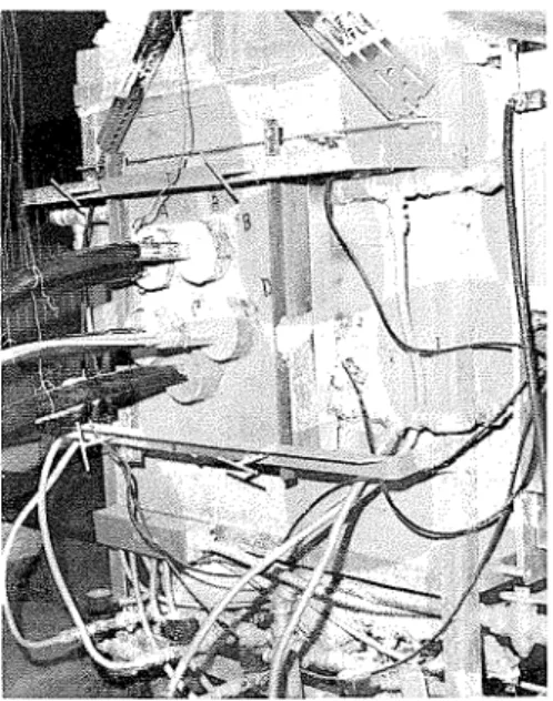
The most significant finding with regard t o achieving good performance under positive pressure conditions was t h a t sleeving cables with thin steel plate proved the most effective. For single cable, protection was provided by a tight wrapping with a 16-inch length of 26-gage steel on the region of the penetration; it was secured with a hose clamp. Figure 3 illustrates a test arrangement in which the penetsation labeled B involves such a sleeve. Immediately beneath penetration B in Figure 3, penetration D involved three small cables, which were t o be sleeved a s a n entity rather than in- dividually. Packing was used t o prevent any slight leakage between cables and sleeve.
It
consisted of a 2-inch cementitious capping backed by 4 inches of alumina-silica-ceramic bulk fiber extending over the length of the visible sleeve together with a n additional inch within the wall.The packing between the thin steel sleeve and the wall opening con- sisted of 5 inches of alumina-silica-ceramic bulk fiber with 1 inch of ce- mentitious capping on the larger cable (B) and 3 inches of fiber with 1%
inches of capping a t each end of the group of three small cables (D). This difference did not seem critical, and a t the end of the 2-hour test period neither sleeve temperature a t the unexposed face of the wall specimen exceeded 280" F.
Two other cables were located in 2-foot lengths of rigid, 2-inch electrical conduit a t the penetrations. T h e space between each of the cables and its respective conduit was filled a t both ends with 4 inches of alumina-silica- ceramic bulk fiber without cementitious capping. At the close of the 2-hour test period, conduit temperatures a t the unexposed face of the wall exceeded 700" F, indicating that the greater metal thickness gave rise t o much higher temperatures than did the thin sheet steel sleeve.
Although the test program did not include floor specimens tested as such in a horizontal plane, it would seem reasonable t o expect perfoimances similar t o those reported. Where aluminum terneplates were involved,
Telephone Cables
Figure 3. Typical test arrangement.
failure was associated with sagging of the cable, but the penetration of floors by vertical cables would be expected t o present fewer problems.
It
should be assumed, however, that, except for certain circumstances on t h e upper floors of high buildings, a positive pressure differential from below t o above will prevail across a floor.The most significant recommendation resulting from the tests is that, where telephone cables penetrate fire partitions a n d adverse pressure dif- ferentials might prevail, it is desirable t o wrap t h e cables tightly with thin steel sheeting long enough to extend several inches beyond both sides of the pal-tition. The opening around the assembly should be closed with several inches of noncombustible, high-temperature fiber and capped with a n inch or two of cementitious sealant.
A P P L I C A T I O N T O B U I L D I N G S
The recommendation concerning t h e use of thin sheet steel sleeves refers t o a condition of adverse pressure differential; t h a t is, t o a positive pressure differential in the fire region with respect t o adjacent regions. Some discussion is desirable of the extent t o which such a condition may prevail. The most likely situation t o warrant adoption of the recommendation is t h a t where cables pass from floor spaces in the lower half of a heated high-rise building into shafts. T h e hazard t o be guarded against is fire in the shaft, and the greatest risk of it develops when an exterior window breaks as a result of fire in a floor space.
The pressures prevailing a t low levels in heated buildings a r e usually much lower than the exterior value a t t h a t level.3 Following window break- age, the inside pressure will very quickly approach t h e exterior value a t that
78 Fire Technology
level and thus will be appreciably higher t h a n in adjoining inside areas. As fires in shafts are t o be avoided, it seems reasonable to implement the recommendation concerning thin sheet steel sleeving on cables passing into shafts under the circumstances just described.
I n the event of fire in a shaft, only massive top venting under favorable circumstances (i.e., tight shaft) would avoid the development of appreciable positive pressure differentials between the shaft and the upper stories of the building. Careful sleeving of the penetrations in these regions is, therefore, also called for.
Under precisely the same conditions, penetrations from t h e fire region t o floors above and below can be expected t o behave poorly, for positive pressure differentials of the same order can prevail following window breakage. If this hazard is t o be guarded against, careful sleeving and packing is again necessary.
Apart from the effect of poorly balanced air-handling systems, t h e previously described conditions involving window breakage in the lower part of a heated high-rise building are the only ones likely t o create a con- sistently high adverse pressure differential. Nevertheless, other cases are worth considering. Even in buildings in which building heating stack action is of a low order (for example, one only three stories high or another of considerable height but unheated) consistently adverse pressure dif- ferentials can be created by stack effect, in this case generated by the fire itself. If the compartment concerned is no more than 10 feet high, however, the total pressure generated will not exceed 0.1 inch WG. Vent openings are not likely t o be confined entirely t o near t h e floor level, and hence t h e distribution of this total pressure will ensure that maximum values will generally not exceed 0.05 inch WG. These will occm a t high levels across walls and, of course, across t h e ceiling-floor assembly a t t h e top of t h e compartment.
Test experience, largely with plastic DWV pipes, suggests that it is a t about this level of pressure t h a t the influence of positive pressure becomes signscant.
It is
thus difficult t o comment on whether or not the recom- mendation concerning thin sheet steel sleeves should be adopted uni- versally for cable penetrations of ceiling-floor assemblies.Yet a third situation in which positive pressuses can be generated con- cerns the expansion of the local atmosphere.
It is bound t o occur during
the development of any fire.It can readily be predicted and has been con-
firmed by measurement t h a t positive pressure differentials resulting from this mechanism will rarely exceed 0.1 inch WG, unless the fire develops with explosive violence.Expansion can only occur a s temperature rises, and resulting positive pressures cannot prevail indefinitely. The test results under discussion indicate that, with noncombustible packing, penetrations will usually survive a considerable positive pressure exposure - for example, 40 min-
Telephone Cables 79 sophisticated sleeving a t penetrations unless subsequent evidence arises t o the contrary.
Summarizing the circumstances under which thin sheet steel sleeving is called for (together with noncombustible packing t o complete t h e closure of a penetration), t h e principal need is in heated high-rise buildings. Penetrations between a floor space and a shaft should be considered care- fully and it is probably desirable t h a t floor-to-floor penetrations a t low levels in the building receive similar attention.
Consistently positive pressure differentials resulting from stack action associated with fire itself also prevail from floor t o floor in both low and high buildings. They are of a lower magnitude, however, than those dis- cussed in relation t o high buildings. The known hazard of floor penetra- tions is currently associated with packing failures, so that properly packed, unsleeved penetrations should not present undue hazard in low buildings.
R E F E R E N C E S
Tamura, G. T., "Computer Analysis of Smoke Movement in Tall Buildings," A S H R A E Transactions, Vol. 75, P a r t 2, pp. 81-92 (1969).
McGuire, J. H., "Penetration of Fire Partitions by Plastic DWV Pipe," Fire Tech- nology, Vol. 9, No. 1 (February 1973), pp. 5-14.
Wilson, A. G. and Tamura, G. T., "Stack Effect in Buildings," National Research Council of Canada, Division of Building Research, CBD 104 (August 1968).
ACKNOWLEDGMENT: Recognition is due t o Bell Canada for its part in t h e planning of the tests and for providing the cables.
This paper is a contribution from t h e Division of Building Research, National Research Council of Canada and is published with t h e approval of the director of t h e Division.
This publication is being distributed by the Division of Building Research of the National Research Council of Canada. I t should not be reproduced in whole or in part without permission of the original publisher. The Division would be glad to be of assistance in obtaining such permission. Publications of the Division may be obtained by mailing the appropriate remittance (a Bank, Express, or Post Office Money Order, or a cheque, made payable to the Receiver General of Canada, credit NRC) to the National Research Council of Canada, Ottawa. KIA 0R6. Stamps are not ac- ceptable.