HAL Id: lirmm-01276757
https://hal-lirmm.ccsd.cnrs.fr/lirmm-01276757
Submitted on 20 Sep 2018
HAL is a multi-disciplinary open access
archive for the deposit and dissemination of
sci-entific research documents, whether they are
pub-lished or not. The documents may come from
teaching and research institutions in France or
abroad, or from public or private research centers.
L’archive ouverte pluridisciplinaire HAL, est
destinée au dépôt et à la diffusion de documents
scientifiques de niveau recherche, publiés ou non,
émanant des établissements d’enseignement et de
recherche français ou étrangers, des laboratoires
publics ou privés.
Design and evaluation of a novel variable stiffness
spherical joint with application to MR-compatible robot
design
Quentin Boehler, Marc Vedrines, Salih Abdelaziz, Philippe Poignet, Pierre
Renaud
To cite this version:
Quentin Boehler, Marc Vedrines, Salih Abdelaziz, Philippe Poignet, Pierre Renaud. Design and
evaluation of a novel variable stiffness spherical joint with application to MR-compatible robot design.
ICRA: International Conference on Robotics and Automation, May 2016, Stockholm, Sweden.
pp.661-667, �10.1109/ICRA.2016.7487192�. �lirmm-01276757�
Design and evaluation of a novel variable stiffness spherical joint with
application to MR-compatible robot design
Quentin Boehler
1∗, Marc Vedrines
1, Salih Abdelaziz
2, Philippe Poignet
2and Pierre Renaud
1Abstract— In this paper, the design of a new variable stiffness spherical joint for MR-compatible robotics is presented. It is based on the use of prestressed cable-driven mechanisms in singular configurations to provide large stiffness variation ranges, including zero stiffness configuration as required by the medical context. An original implementation is proposed, with a prestress adjustment system using pneumatic energy and taking advantage of multimaterial additive manufacturing. The proposed component combines compactness, MR-compatibility and is lightweight. The system is evaluated on a dedicated experimental setup with validation of the expected behavior, with in particular a very large achievable range of stiffnesses. The approach is effective for the design of such device and constitutes a novel solution for the design of variable stiffness devices with complex motions.
I. INTRODUCTION
In the field of interventional radiology, imaging modalities are used during medical tasks. In the case of MR-guided percutaneous procedures, a needle is to be manipulated and inserted while the patient is in an MRI scanner. Performing the task manually is challenging because of the lack of space and manipulability within the MRI tunnel, and the limited accessibility to the patient. A number of robotic needle holders have therefore been proposed to provide assistance to the radiologist in the needle manipulation task [1], especially for interventions on the prostate [2]. In the case of abdominal procedures, the design of a robotic assistance is particularly difficult, because of the organ motions induced by the patient breathing. It has indeed been observed that a static grasping of a needle inserted in an organ such as the liver causes tissue lacerations [3], a situation that is obviously not admissible. An elaborated needle grasping strategy is needed.
Mounting the robotic needle holder on the patient can re-duce the relative motion between the needle and the targeted tissues. The breathing impact is however complex and this only partially solves the problem [4]. A refined approach is to insert the needle periodically, at the same instant in the breathing cycle, and to release the needle meanwhile. A dedicated needle grasping device has been introduced for that in [5]. The safety and efficiency of the approach can however be questioned, since needle grasp and release cycles are then frequent, increasing risks of failure in the grasping phase. An alternate approach is to maintain the needle grasping by the robotic device, and to modulate the stiffness of the robot-needle connection during the breathing cycle. A rigid connection can ensure insertion accuracy, and a compliant
∗Corresponding author:[email protected] 1
ICube - CNRS - University of Strasbourg - INSA Strasbourg
2
LIRMM - CNRS - University of Montpellier
Fig. 1. General view of the proposed variable stiffness spherical joint.
grasping avoids tissue damage. This original approach is at the center of this paper, by developing the necessary variable stiffness component.
The desired variable stiffness joint has to fulfill five main requirements. First, observation of procedures shows that the needle motion induced by breathing can be described as a rotation of arbitrary axis around the insertion point. The variable stiffness joint must therefore be a compliant spherical joint, with a center located close to the tissue surface. Second, the MRI environment introduces constraints in terms of materials and selection of active components [6]. Ideally, the joint has to be designed using polymer materials, without any active element inside the scanner for the stiffness control. Third, as mentioned earlier, space is restricted which means the proposed joint design must be compact. Fourth, the efficiency of the approach will be higher if the joint is integrated in a patient-mounted robot, that reduces the influence of breathing motion. A lightweight design is thus needed. Fifth, and probably as the most stringent require-ment, the stiffness variation has to be very large. It is needed to ensure a correct stiffness for needle guidance during insertion, and to lower the stiffness so the joint influence on the needle motion is actually lower than the one of the tissues. Given the biomechanical properties of the liver for instance, it means we almost need to reach a zero stiffness. To our knowledge, such a set of design constraints constitutes an original problem that has not yet been solved in the literature.
A number of variable stiffness joints have been proposed, with applications for intrinsically safe robotics [7]. Springs or elastic elements are usually integrated within the component to provide a passive compliance, in opposition to the active
1 2 k, t0
dx
l
dθ
Fig. 2. Example of a 2-cable prestressed mechanism. The platform is represented in blue at the center and the cables in black plain lines.
Re Ri Op, O x z y u1 1 2 3 4 5 6 r1
Fig. 3. The proposed architecture, represented in its nominal configuration. The end-effector is represented by the blue sphere at the center of the figure and the base by the dotted circles. Cables are plotted as black plain lines and the anchor points as black dots. The three pairs of antagonistic cables are{1, 2} , {3, 4} and {5, 6}.
compliance by control. Compliance variation is obtained using three main strategies. The physical structure of a spring can be altered as in [8], [9], [10], where the effective length of the elastic elements is modified to adjust the stiffness. The geometry of the transmission between the load and the elastic elements can also be changed to provide the stiffness variation. This can be implemented by adjusting either the position of a cam [11], or the transmission ratio through a variable moment arm [12], [13], [14]. These two strategies are based on a geometry modification that requires the mo-tion of several rigid components. Such momo-tions may hinder the compactness and the lightweight properties that are de-sired in our context. The third strategy consists in modulating the elastic element prestresses by means of an antagonistic arrangement [15], [16], [17], [18]. The number of moving elements is reduced but it opens in our context the question of the design of nonlinear springs with very large stiffness variation capability. To our understanding, a zero stiffness configuration can not indeed easily be obtained through the prestress of the system with a simple arrangement. Pre-stressed cable-driven mechanisms in singular configurations constitute an interesting class of systems in our context, since they are known [19] to exhibit very large stiffness variation, including zero stiffness configuration. The stiffness is tuned by adjusting a level of cable prestress. No specific component such as a nonlinear spring is therefore needed, and fast prestress modification can be performed. Such mechanisms have been therefore successfully considered in
the context of vibration control [20]. The use of cables is in addition an advantage for compactness, weight and MR-compatibility as demonstrated for instance in [21] for a needle positioning device. As a consequence, we propose in this paper the design of a new spherical variable stiffness joint based on a prestressed cable-driven mechanism. This constitutes the first main contribution of the paper, with the component modeling, design and an experimental evidence of its interest.
The use of cable-driven mechanisms is of interest if their actuation, here for prestress generation, is properly designed. MR-compatibility and compactness constitute here strong design constraints. As a second main contribution of the paper, we introduce an original design to solve this issue, combining recently developed multimaterial additive manufacturing and pneumatic actuation.
In the following section, the architecture of the proposed spherical variable stiffness joint is introduced and justified. The joint stiffness modeling and evaluation is developed in section III, before presenting the design process and result in section IV. The implementation and experimental evaluation of the device are then performed in section V, before concluding.
II. ARCHITECTURE PROPOSITION
A. Conditions of existence of prestressed cable-driven mech-anisms
A simple prestressed cable-driven mechanism is repre-sented in Fig. 2. The platform located at the center is connected to the base by means of two elastic cables, of same stiffnesses and tensions, denoted respectivelyk and t0. A first necessary property for such a mechanism to be of interest is its prestressability [19]: we can here impose any value oft0 in the cables without any modification of the configuration. The second property is its singular behavior: the cables are parallel and pass through the center of the end-effector. In such a configuration, infinitesimal vertical translationdx and rotation dθ are possible without any change in the cable lengths. Because of these two properties, the translational and rotational stiffnesses are fully controlled by the cable prestresses, and the stiffnesses can be made null witht0= 0. In other words, because of the singular configuration, the stiffness is not dependent on the cable elasticity, and the cable tensions can be modified to adjust the device stiffness. The directions where the mechanism can exhibit zero stiffness are designated as infinitesimal flex [22].
B. The proposed architecture
We are interested in building a spherical joint of variable stiffness. This means the selected architecture has to exhibit the two previous properties, with in particular infinitesi-mal flex that correspond to the three possible independent rotations in space. The architecture represented in Fig. 3 corresponds to these requirements, as demonstrated in the following.
The mechanism is composed of three pairs of antagonistic cables that link an end-effector of center Op to a base
associated to a reference frame (O, x, y, z). The points O andOpare coincident. The anchor points on the base and the end-effector are respectively located along circles of radius ReandRiand centersO and Op. The unit vectors uiand ri denote respectively the direction vector and the moment arm vector of the ith cable. The cables are of same stiffness k and prestresst0.
The two previously introduced properties can be evaluated using the Jacobian J of the mechanism. This Jacobian matrix relates the cable deformations dl = [dl1, ..., dl6]T to the vector of small displacements of the end-effector dP = [dx, dy, dz, dθx, dθy, dθz]T
with respect to the reference frame so that [23]
JdP = dl (1)
Using the virtual work principle, the Jacobian matrix can also be seen as relating the vector of cable tensions t and the value of an applied external wrench We:
JTt= We (2) where t= [t1, ..., t6]T is the set of cable tensions.
The first property is the prestressability, that is obtained if the mechanism remains in equilibrium while We = 0 and t 6= 0. From Eq. (2) one can see that a necessary condition is that the nullspace basis of JT
spans the cable tensions that are compatible with this equilibrium. For the proposed architecture, one can easily determine this basis as [1, 1, 0, 0, 0, 0]T,[0, 0, 1, 1, 0, 0]T,[0, 0, 0, 0, 1, 1]T, mean-ing that each pair of antagonistic cables can be independently prestressed without influence on the configuration. The first property is satisfied.
The second property can be assessed by determining the nullspace basis of J as it corresponds to the dis-placements of the end-effector that can be performed without cable deformations (see Eq. (1)). This basis is [0, 0, 0, 1, 0, 0]T,[0, 0, 0, 0, 1, 0]T,[0, 0, 0, 0, 0, 1]T
, which means the infinitesimal flex correspond effectively to the three rotations of the end-effector around the point O. The second property is obtained as well.
III. DEVICE MODELING AND EVALUATION The two previous necessary conditions are fulfilled by the proposed architecture. Given our requirements, we need in addition to carefully analyze the possible motions of the end-effector. Because of the elastic nature of the cables, trans-lational displacements are indeed possible from a kinematic point of view. They may become significant if the component dimensions are not properly chosen. In the following, a device modeling is introduced to compute and normalize the translational and rotational stiffnesses, so that we can assess and compare their values during the component synthesis. A. Derivation of the stiffness matrix in the nominal config-uration
As a first step, we can derive the stiffness matrix K that relates the small displacements of the end-effector to an applied external wrench when the mechanism is in its nominal configuration, represented in Fig. 3. As suggested
in [19], the stiffness matrix is split to consider separately the elastic stiffness Ke, due to the elasticity in the cables, and the antagonistic stiffness Ka, coming from the antagonistic forces, such that K= Ke+ Ka. One can show that in the nominal configuration, for matrices expressed in O in the reference frame,
Ke= diag(2k, 2k, 2k, 0, 0, 0) (3) and Ka has the following structure:
Ka= diag(ka t, k a t, k a t, k a θ, k a θ, k a θ) (4) with ka
t the antagonistic translational stiffness and kθa the rotational antagonistic stiffness, of following expression:
kta= 4t0 Re−Ri (5) ka θ = 4Rit0( Re Re−Ri) (6) The two matrices are diagonal thanks to the symmetrical arrangement of the cables. The pointO is therefore the so-called elastic center of the mechanism [24]. For the same reason, the three translational stiffnesses are identical, as well as the three rotational stiffnesses. As outlined in the previous section, Ke is singular as the rotation of the end-effector is possible without deformation in the cables. The rotational stiffness is thus only controlled by the level of prestress, without any influence of cable elasticity. The first consequence is that the rotational stiffness can be lowered to reach zero by adjusting the prestress value t0. The second consequence is that it is possible to adjust the ratio between the translational and rotational stiffnesses by selecting prop-erly the cable stiffness k, since this parameter only affects the translational stiffnesses. The translational stiffness can be made predominant over the rotational one by choosing a large enough value ofk.
B. Computation of the stiffness matrix for other configura-tions
For low stiffnesses, the end-effector displacement can be significant. The validity of the previous analysis, performed in the nominal configuration, could then be questionable. A computation method of the stiffness matrix for any given configuration of the end-effector is therefore elaborated. The analytical expression of the stiffness matrix K for any configuration of the end-effector is cumbersome. We therefore compute its value numerically, in four steps:
1) Computation of ui and ri. 2) Computation of t and J.
3) Computation of We by solving Eq. (2). 4) Computation of K.
Using this sequence, any cable behavior can be considered. We can include in particular nonlinear cable stiffness models by simply using an expression ofk that is dependent on the cable tensions.
C. Normalization of the stiffness matrix
The determination of the stiffness matrix coefficients is not sufficient to qualify the component behavior. One more step is needed to compare the translational and rotational stiffnesses, of different dimensions. Among existing normal-ization techniques, the approach proposed in [25] for the analysis of compliant joints is adopted. The component ˆkij, i ∈ [1, 3], j ∈ [1, 3], of the normalized stiffness matrix ˆK is obtained as follows ˆ kij = kij/kmax t ifi = j, i ≤ 3 kij/(kmax t L 2 ) ifi = j, i ≥ 4 kij/(kmax t L) ifi 6= j withkmax
t the maximum translational stiffness andL a lever arm length that is chosen considering the application point of the external wrench. In the following we can therefore directly compare the stiffness matrix components that are in addition dimensionless.
IV. COMPONENT DESIGN A. Component integration
The interest of the proposed architecture is closely related to its integration as an MR-compatible component. We need in particular to take into account the prestress generation system, not yet selected and that may constrain the device dimensions.
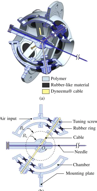
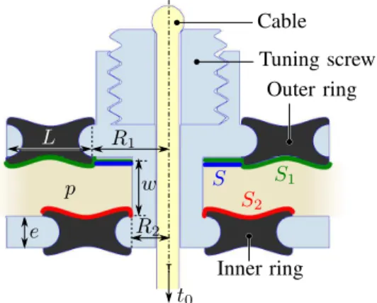
The six cables have to be uniformly prestressed. Their different orientations make the design of a prestress system difficult. The solution we propose is based on pneumatic actuation. Such actuation mean is usually interesting to develop surface forces. The interest of our design relies in the use of such surface forces by means of a spherical shell produced using multimaterial additive manufacturing (MMAM), here with the PolyJet process (Stratasys®). The CAD design of the whole device is depicted in Fig.4 and its physical implementation in Fig. 1. The joint is logically of spherical shape, with a mounting plate for connection with the robotic needle holder. The six cables are passing through the mounting plate to reach the needle guide. MMAM allows us here to produce as a single element a structure composed of rigid polymer and rubber-like material. The number of elements is lowered thanks to the process, which is beneficial to the compactness. The use of rubber-like material allows us in addition to create compliant cylinders to apply prestress on the cables. A detail on these compliant elements is represented in Fig. 5. They are composed of two rings. The difference between the areas of surfaceS1 on the outer ring and surfaceS2on the inner ring is used to create a prestress force when the pressurep in the chamber (Fig. 4) increases. A tuning screw is integrated to adjust the initial prestress. For the control, a single air input is needed that communicates with the chamber.
B. Design parameters and synthesis
For the synthesis, we set the outer diameter of the compo-nent to 60 mm, that we consider as the maximum admissible value for the applicative context. For ease of use and safety,
Polymer Rubber-like material Dyneema® cable (b) (a) Ri Re Cable Chamber Rubber ring Tuning screw Air input Op Needle Mounting plate
Fig. 4. CAD of the device. (a) 3D-sectioned view. (b) Cross-section in the plane of a pair of antagonistic cables.
we set the air pressure to 1.5 bar, and maximum tensions to 20 N. The range of motion of a needle is dependent on the organ of interest in the applicative context, and still need a precise evaluation. For this proof of concept, the maximum angular deflection is chosen equal to 25◦.
The component geometry is finally mainly defined by seven parameters (Re, Ri, R1, R2, L, w, e). The parameters e and w are respectively set to 2 and 4 mm to satisfy manufacturing and assembly constraints. The external radius Re is directly related to the chosen external diameter. The internal radiusRi and the parameters related to the prestress adjustment system are iteratively determined. During each iteration, the cable stiffness model needed in the modeling of section III is identified from the Finite Element Analysis (FEA, PTC Creo Simulate) of the prestress adjustment sys-tem with its current geometry. The Dyneema® cable is here
S1 S2 p Outer ring Inner ring Cable S t0 Tuning screw e R1 R2 w L
Fig. 5. Prestress adjustment system. The prestress t0 is set through the
pressure p applied on the surface S. TABLE I
SIMULATIONS RESULTS FORp = 0AND1.5BAR IN THE NOMINAL CONFIGURATION.
p (bar) t0(N) kt(N/mm) kθ(N.mm/rad) kˆθ(-)
0 0 12.8 0 0
1.5 12.5 17.8 656.8 0.01
supposed rigid and the parameterk only depends on the be-havior of the rubber rings. A second order polynomial model of the cable stiffness best describes the system behavior. In addition, a linear relationship between the control pressure p and the prestress t0 is identified. The performance of the device can then be estimated using the models of section III. The geometry is updated from this evaluation. At each step, the FEA is also used to verify the material resistance in the compliant elements. The rubber-like material deformation must remain under 50% for a 1.5 bar pressure and rotations of 25◦.
The final geometry is characterized by Re = 17.5 mm, Ri = 7.5 mm,R1= 5 mm,R2= 2.5 mm,L = 61 mm, w = 4 mm,e = 2 mm. The obtained normalized stiffnesses for min-imum and maxmin-imum pressures in the nominal configuration are given in Table I. Because of the normalization, ˆktis equal to 1 and not reported. For the two pressure levels, ˆkt> 100ˆkθ which means the device can be considered as a compliant spherical joint. It is also important to note the large angular stiffness variation within the prescribed pressure range. A maximum rotational stiffness of 656.8 N.mm/rad can here be reached, and a zero minimum value in the nominal configuration. For end-effector rotations in the [0, 25] ◦ range, the stiffnesses for minimum and maximum pressures both increase. Their respective mean values are equal to 279.1 and 864.2 N.mm/rad, which means that the stiffness variation is greater than 3 even for large deflections.
V. EXPERIMENTAL EVALUATION
An experimental evaluation is performed to confirm the interest of the design. The joint design is slightly modified to ease its evaluation (Fig. 6). The needle is actually replaced by a dedicated end-effector characterized by a lever arm
L
v
Op Base
End-effector
Fig. 6. 3D section of the prototype
L =61 mm. The end-effector axis is defined by (Op, v) with v= [1, 1, 1]T
as depicted in Fig. 6. All the parts are produced with a Connex 350 machine (Stratasys®).
A. Rotational stiffness evaluation
As a first step, the rotational stiffness about the end-effector axis is measured. The experimental setup is depicted in Fig. 7. For this evaluation, we desire to apply a pure torque around the end-effector axis. As a consequence, a guidance system is added at the tip of the end-effector. It includes bearings (see Fig. 7(b)) to avoid any parasitic translation in the protocole. The torque T is generated using a pulley of radiusr =25 mm fixed to the end-effector, and a mass m so thatT = rmg with g the gravity acceleration. Nine different weights are applied, for three different pressures. A vision-based evaluation of the angular deflection θ is performed (Digital camera Nikon D70, 6.1MP resolution, 70 mm lens) using four visual markers placed on the pulley. The angle measurement accuracy is in the order of 0.1◦.
Experimental results and simulation predictions for the experimental conditions are superimposed on Fig. 8. We can first notice that the stiffness variation is as large as it was predicted during the design: the angular deflection can be reduced by more than 87% all along the angular stroke when adjusting the pressure p from 0 to 1.5 bar. The reduction even reaches 96% for angles lower than 10◦. The mean value of the relative errors between prediction and experimental results is lower than 25%. These relative errors increase quickly with the angular deflection. Large deflections are actually situations where the elastic stiffness contribution is significant. Errors in the modeling of the nonlinear behavior of the rubber-like material may therefore be mainly responsible of the discrepancies.
B. Translational stiffness evaluation
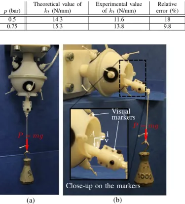
As a second step, the translational stiffnessktis evaluated in the direction v of the end-effector axis. A load P is now applied in the v direction as depicted on Fig. 9(a). Two different pressure levels are set to assess the influence of the prestress. 6 visual markers are extracted with the same vision setup, 4 on the end-effector and 2 on the base, as represented in Fig. 9(b). The measurement accuracy of the deflection dv caused by the application of the load is
P = mg Air input Camera v Op Loading pulley T Visual marker Bearing Guiding part Pulley (a) (b) End-effector (c)
Fig. 7. Experimental setup for rotational stiffness evaluation. (a) General view. (b) Close-up on the loading device. (c) CAD cross section of the loading device. p=0 bar p=0.75 bar p=1.5 bar Angular deflectionθ (°) T o rq u e T (N .m m ) 0 10 20 0 20 40
Fig. 8. Experimental results for a rotation about v. Measurements represented by stars and simulation predictions in plain line.
estimated equal to 0.05 mm. The translational stiffnessktis computed as the ratio between P and dv, with dv of small amplitude, below 1 mm. The results are given in Table II. As anticipated, the translational stiffness increases with the pressure. The modeling prediction errors are below 20%. More importantly, the values of translational and rotational stiffnesses obtained experimentally can be compared, using the normalization introduced earlier. For p = 0.75 bar, the normalized translation stiffness is 156 times higher than the normalized rotation stiffness. This outlines the satisfactory kinematic behavior, with a joint that is equivalent to a spherical joint, with variable stiffness.
TABLE II
EXPERIMENTAL RESULTS FOR THE ESTIMATION OFkt.
p (bar) Theoretical value of kt (N/mm) Experimental value of kt(N/mm) Relative error (%) 0.5 14.3 11.6 18 0.75 15.3 13.8 9.8 (a) (b) P = mg
Close-up on the markers Visual markers P = mg vi j A
Fig. 9. Experimental setup for translational stiffness evaluation (a) and behavior analysis under complex loading (b).
C. Evaluation of the kinematic behavior under complex loading
As a final step, experiments are performed with application of weights to apply at the same time a force and a moment on the end-effector (Fig. 9(b)). The device is mounted with two successive different orientations of its base, so that the displacements occur either in the(A, i, v) plane (Fig. 9(b)) or in the(A, j, v) plane. For three pressure levels (0, 0.75 and 1.5 bar), the end-effector is increasingly loaded until the 25◦maximum angular deflection is reached. The end-effector displacements are estimated with an accuracy of 0.2 mm.
The end-effector displacement are equal to 0.6, 0.4 and 0.4 mm for pressures respectively equal to 0, 0.75 and 1.5 bar. These values are in the order of the model pre-dictions, do not exceed 1 mm, which is compatible with the application context.
VI. CONCLUSION AND PERSPECTIVES In this paper, the design of a novel variable stiffness spherical joint has been presented. The proposed archi-tecture is based on a prestressed cable-driven mechanism, which arrangement was first justified, before developing its stiffness models. Prestress generation is originally obtained combining pneumatic actuation and multimaterial additive manufacturing. This allows us to propose a solution that
is satisfactory in terms of compactness, weight, and MR-compatibility.
In terms of kinematic behavior and stiffness variation, the experimental evaluation provides satisfactory results. The spherical behavior of the design is confirmed as well as the large angular stiffness variation capability, including zero stiffness configuration.
Further work will now consists of the integration of the device within a robotic needle holder and its evaluation during lab and in vivo experiments. This evaluation will include in particular impact assessment on laceration risks. From this, synthesis of the device will be refined in order to explore even more compact geometries. As an alternate research perspective, we will also investigate the design of Remote Center of Compliance (RCC) device, that could also be of interest in such contexts.
ACKNOWLEDGMENT
This work was supported by French state funds man-aged by the ANR within the Investissements d’Avenir pro-gramme (Robotex 10-EQPX-44, Labex CAMI - ANR-11-LABX-0004) and by the Région Alsace and Aviesan France Life Imaging infrastructure.
REFERENCES
[1] M. M. Arnolli, N. C. Hanumara, M. Franken, D. M. Brouwer, and I. A. M. J. Broeders, “An overview of systems for CT- and MRI-guided percutaneous needle placement in the thorax and abdomen,” IJCARS, 2014.
[2] A. Krieger, R. C. Susil, C. Ménard, J. Coleman, G. Fichtinger, E. Atalar, L. L. Whitcomb, et al., “Design of a novel mri compatible manipulator for image guided prostate interventions,” IEEE Trans. Biomed. Eng., vol. 52, no. 2, pp. 306–313, 2005.
[3] D. Sun, C. Willingham, A. Durrani, P. King, K. Cleary, and B. Wood, “A novel end-effector design for robotics in image-guided needle procedures,” Int J Med Robot., vol. 2, no. 1, pp. 91–97, 2006. [4] B. Maurin, B. Bayle, O. Piccin, J. Gangloff, M. de Mathelin,
C. Doignon, P. Zanne, and A. Gangi, “A patient-mounted robotic platform for ct-scan guided procedures,” IEEE Trans. Biomed. Eng., vol. 55, no. 10, pp. 2417–2425, 2008.
[5] O. Piccin, N. Kumar, L. Meylheuc, L. Barbé, and B. Bayle, “Design, development and preliminary assessment of grasping devices for robotized medical applications,” in ASME 2012 IDETC/CIE, 2012, pp. 65–73.
[6] K. Chinzei, R. Kikinis, and F. A. Jolesz, “MR compatibility of mechatronic devices: design criteria,” in Medical Image Computing and Computer-Assisted Intervention–MICCAI’99. Springer, 1999, pp. 1020–1030.
[7] B. Vanderborght, A. Albu-Schaeffer, A. Bicchi, E. Burdet, D. Cald-well, R. Carloni, M. Catalano, O. Eiberger, W. Friedl, G. Ganesh, M. Garabini, M. Grebenstein, G. Grioli, S. Haddadin, H. Hopp-ner, A. Jafari, M. Laffranchi, D. Lefeber, F. Petit, S. Stramigioli, N. Tsagarakis, M. V. Damme, R. V. Ham, L. Visser, and S. Wolf, “Variable impedance actuators: A review,” Rob Auton Syst, vol. 61, no. 12, pp. 1601 – 1614, 2013.
[8] T. Morita and S. Sugano, “Design and development of a new robot joint using a mechanical impedance adjuster,” in Robotics and Au-tomation (ICRA), 1995 IEEE International Conference on, vol. 3, May 1995, pp. 2469–2475 vol.3.
[9] J. Choi, S. Hong, W. Lee, S. Kang, and M. Kim, “A robot joint with variable stiffness using leaf springs,” IEEE Trans. Robot., vol. 27, no. 2, pp. 229–238, April 2011.
[10] J. Schuy, P. Beckerle, J. Wojtusch, S. Rinderknecht, and O. von Stryk, “Conception and evaluation of a novel variable torsion stiffness for biomechanical applications,” in Biomedical Robotics and Biomecha-tronics (BioRob), 2012 4th IEEE RAS EMBS International Conference on, June 2012, pp. 713–718.
[11] S. Wolf, O. Eiberger, and G. Hirzinger, “The DLR FSJ: Energy based design of a variable stiffness joint,” in Robotics and Automation (ICRA), 2011 IEEE International Conference on, May 2011, pp. 5082– 5089.
[12] A. Jafari, N. Tsagarakis, and D. Caldwell, “AwAS-II: A new actuator with adjustable stiffness based on the novel principle of adaptable pivot point and variable lever ratio,” in Robotics and Automation (ICRA), 2011 IEEE International Conference on, May 2011, pp. 4638–4643. [13] L. Visser, R. Carloni, and S. Stramigioli, “Energy-efficient variable
stiffness actuators,” IEEE Trans. Robot., vol. 27, no. 5, pp. 865–875, Oct 2011.
[14] B.-S. Kim and J.-B. Song, “Design and control of a variable stiffness actuator based on adjustable moment arm,” IEEE Trans. Robot., vol. 28, no. 5, pp. 1145–1151, Oct 2012.
[15] C. English and D. Russell, “Mechanics and stiffness limitations of a variable stiffness actuator for use in prosthetic limbs,” Mech Mach Theory, vol. 34, no. 1, pp. 7–25, 1999.
[16] S. Migliore, E. Brown, S. P. DeWeerth, et al., “Biologically inspired joint stiffness control,” in Robotics and Automation (ICRA), 2005 IEEE International Conference on. IEEE, 2005, pp. 4508–4513. [17] F. Petit, M. Chalon, W. Friedl, M. Grebenstein, A. Albu-Schaeffer, and
G. Hirzinger, “Bidirectional antagonistic variable stiffness actuation: Analysis, design and implementation,” in Robotics and Automation (ICRA), 2010 IEEE International Conference on, May 2010, pp. 4189– 4196.
[18] M. Catalano, G. Grioli, M. Garabini, F. Bonomo, M. Mancinit, N. Tsagarakis, and A. Bicchi, “Vsa-cubebot: A modular variable stiffness platform for multiple degrees of freedom robots,” in Robotics and Automation (ICRA), 2011 IEEE International Conference on, May 2011, pp. 5090–5095.
[19] M. Azadi, S. Behzadipour, and G. Faulkner, “Antagonistic variable stiffness elements,” Mech Mach Theory, vol. 44, no. 9, pp. 1746–1758, 2009.
[20] ——, “A variable spring using a tensegrity prism,” in ASME 2009 IDETC/CIE, 2009, pp. 35–43.
[21] S. Abdelaziz, L. Esteveny, P. Renaud, B. Bayle, L. Barbé, M. De Math-elin, and A. Gangi, “Design considerations for a novel mri compatible manipulator for prostate cryoablation,” IJCARS, vol. 6, no. 6, pp. 811– 819, 2011.
[22] C. Calladine and S. Pellegrino, “First-order infinitesimal mechanisms,” International Journal of Solids and Structures, vol. 27, no. 4, pp. 505 – 515, 1991.
[23] S. Behzadipour and A. Khajepour, “Stiffness of cable-based parallel manipulators with application to stability analysis,” ASME J. Mech. Design, vol. 128, no. 1, pp. 303–310, 2006.
[24] N. Ciblak and H. Lipkin, “Centers of stiffness, compliance, and elas-ticity in the modelling of robotic systems,” in ASME 2012 IDETC/CIE, vol. 72, 1994, pp. 185–195.
[25] Y.-M. Moon, B. P. Trease, and S. Kota, “Design of large-displacement compliant joints,” in ASME 2002 IDETC/CIE, 2002, pp. 65–76.