HAL Id: hal-00189272
https://hal.archives-ouvertes.fr/hal-00189272
Submitted on 24 Mar 2020
HAL is a multi-disciplinary open access
archive for the deposit and dissemination of
sci-entific research documents, whether they are
pub-lished or not. The documents may come from
teaching and research institutions in France or
abroad, or from public or private research centers.
L’archive ouverte pluridisciplinaire HAL, est
destinée au dépôt et à la diffusion de documents
scientifiques de niveau recherche, publiés ou non,
émanant des établissements d’enseignement et de
recherche français ou étrangers, des laboratoires
publics ou privés.
Ewod Digital Microfluidics for Lab On a Chip
Yves Fouillet, D. Jary, A.G. Brachet, Jean Berthier, R. Blervaque, Laurent
Davoust, Jean-Maxime Roux, Jean-Luc Achard, C. Peponnet
To cite this version:
Yves Fouillet, D. Jary, A.G. Brachet, Jean Berthier, R. Blervaque, et al.. Ewod Digital
Microflu-idics for Lab On a Chip. ASME 4th International Conference on Nanochannels, Microchannels, and
Minichannels, Jun 2006, Limerick, Ireland. �10.1115/ICNMM2006-96020�. �hal-00189272�
Proceedings of ASME ICNMM2006 4th International Conference on Nanochannels, Microchannels and Minichannels June 19-21, 2006, Limerick, Ireland
Paper No. ICNMM2006-96020
KEYNOTE PAPER
EWOD DIGITAL MICROFLUIDICS FOR LAB ON A CHIP
Y. Fouillet1, D. Jary1, A.G. Brachet1, J. Berthier1, R. Blervaque1,L. Davous2, J.M. Roux1, J .L Achard2 and C. Peponnet1.
1
Laboratoire d'Electronique et de Technologie de l'Information (LETI) - CEA/LETI/DSIS/MSB – Grenoble LETI 17 av. des Martyrs, 38054 Grenoble Cedex 9. France. Mail : [email protected]
2
Laboratoire des Ecoulements Géophysiques et Industriels (LEGI) - INPG/CNRS/UJF - Grenoble LEGI, 1021 rue de la Piscine, 38400 St Martin d'Hères.
ABSTRACT
This paper presents a brief overview of Electro Wetting On Dielectric (EWOD) microdroplet actuation technology fluidic behaviour. EWOD specifics are compared with other digital microfluidics actuation modes. In particular ease of integration with complex protocols is emphasized.After reviewing the electro)wetting principle and various Electro)Hydro)Dynamic (EHD) phenomena; we compare various EWOD configurations for Lab on a Chip. Two fluid functionalities will be detailed: on)chip droplet dispensing, and mixing. We cover chip architecture and the benefits of organizing these chips as fluidic microprocessors. Finally, real time PCR (Polymerase Chain Reaction) within a 64 nl droplet is described as an illustration of a biological application using EWOD.
I. INTRODUCTION
A Lab on a chip may be described as a microsystem capable of performing chemical or biological analysis, within a completely miniaturized and integrated component. The concept of Micro Total Analysis System was introduced by Manz [1] and Harrison [2] in the early 90’s. Since then, we have witnessed a rapid expansion of Lab On a Chip studies showing at the same time numerous challenges and difficulties. Biology has been a major focus for lab on a chip development ranging from genomics to cell research via proteomics. Fields such as medical diagnosis, pharmaceutical screening, and environmental control have been impacted by microfluidics. Even implantable biochips for in)vivo drug delivery are concerned . However, compared to the number of publications, the number of commercial microfluidic based device remains small revealing the difficulties of miniaturization and integration of complex protocols.
This diversity of applications has given rise to a large number of technologies based on the manipulation of small volumes of liquids. As such, microfluidics has become a key research theme involving multidisciplinary competencies, from mechanics, physical chemistry, biology, to microtechnology. Thus we have witnessed the emergence of a huge variety of fluidic methods for the manipulation and control of fluids at a small scale. These various microfluidic approaches have all advantages and inconvenients, and it is rather difficult to predict which solutions, for which application will prevail.
A large number of chemical and biological reactions have already been performed on microfluidic chips, albeit in research laboratory settings. Only a few commercialized microfluidic systems, such as the Agilent 2100 Bioanalyzer [3], have been widely adopted. The reason behind this successful integration can be explained by the simplicity of the fluidic protocols, the ease of use and the robustness of the method. Thus a remaining challenge is the successful integration of a complex protocol within a single component. By complex protocol we intend performing an analysis from sample preparation to data analysis (e.g. point of care diagnostic micro system). Indeed, the system (instrumentation, microcomponent and protocol) needs to be autonomous, portable and reliable while handling numerous fluidic functions like calibrated volume dispensing, sub)volume fragmentation, coalescence, mixing, reagent storage…
Liu et al. [4] illustrates this integration concept, where a credit card sized chip performs a dozen elementary functions in series. However, just one sample is processed on a fairly complex protocol. One may furthermore want to perform several analyses in parallel in order to study the presence of several pathogens. If this is the case, chip design and associated
instrument using pump and valves may become quickly difficult to integrate.
From a fluidic standpoint, it is not only a matter of moving a liquid, but also of implementing a set of basic fluidic functions leading to a fully integrated system. The integration complexity of the system must be looked not only at the micro component level but also at the instrumentation level. As we can see the choice of a microfluidic method displaying a strong promise of integration, will be key for lab on chip dissemination…
Being aware not only of the need but also of the difficulty of integrating a complex biological protocol, a research program on EWOD actuated digital microfluidics was initiated at the CEA Leti. The concepts and applications of EWOD based droplet manipulation were first demonstrated at UCLA [5] and Duke University [6]. Many papers in this domain have confirmed that the approach is promising and the technology is maturing. One additional goal of this article is to survey this particular subfield of microfluidics. Key results and observations on EWOD actuation are reported here.
2. DIGITAL MICROFLUIDICS
The most common approach in microfluidics consists in filling and pumping liquids through a network of micro fabricated channels by pressure driven flow. When several reactions are moving through a channel in a single)phase fluidic flow, the risk of axial broadening of reaction zones via Brownian and Taylor diffusion [7] becomes an issue. This broadening is particularly a problem for long protocols, when throughput is essential or when reagent concentrations need to be precisely controlled. A flat speed profile obtained with electro)osmotic pumping is a better alternative but is harder to control as it is coupled to selective molecular migration due to electrophoresis. It is therefore often advantageous to physically separate reagents from one another as done in digital microfluidics.
Digital microfluidics often consists in using two immiscible phases, where reactions are formed and moved in an immiscible fluid by pumps or pressure driven flow. This method is called droplet)based channel microfluidics and is characterised by plug or slug flow. For certain flow rates, the two phases may be continuously injected with droplet formations ensured through hydrodynamic effects [8, 9]. Indeed, droplet based channel microfluidics is an easy method that appears very efficient for high speed droplet formation with well controlled characteristics. While it is possible to divide or sort droplets [10, 11], it appears difficult to independently manipulate every droplet in terms of droplet specific reagent addition or when droplet specific protocols necessitating feed back loops are used [12]. Indeed, individual droplet management for droplet)based channel microfluidics implies complex fluidic injection systems capable of switching reagents. Thus, droplet)based channel microfluidics is well adapted when droplets can be managed collectively in a batch mode all having the same protocol and reagents. This limitation of droplet)based channel microfluidics is mainly due to the global actuation mode which is governed externally by pressure conditions existing at the channel entries or exits.
Another approach to digitalization of a given liquid volume consists in using deformable walls and confining reactions to reactive chambers. This method is most promising when each
chamber can be independently manipulated. A stunning example of this approach is presented by Thorsen et al. [13] where a component moulded out of a soft material (PDMS) implements thousands of interconnects controlling over one hundred chambers. This is a significant departure from the approach described previously, given that reactional chambers are made independent and can be manipulated one by one resulting in great flexibility for integration of complex protocols.
In order to establish digitized reactive volumes, droplets can be used as a microreactor and displaced on a planar surface from one functional zone to another. Several droplet actuation methods exists for droplet translocation such as dielectrophoresis [14], thermo capillarity [15], magnetic levitation [16], or acoustical surface waves [17]. The ability to move droplets in two dimensional space is obviously an enormous advantage when compared to other channel based solutions where droplets must follow a linear trajectory defined by the fluidic chip design.
However, complex protocols not only need droplet displacement, but also droplet splitting, dispensing and merging. To do so the actuation method needs to allow for significant modification of the droplet surface interface and shape.
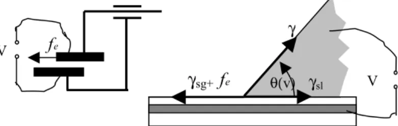
EWOD is one of the rare methods that allow such manipulation and transformations. Indeed, electrowetting can modify the contact angle of a droplet on a surface thanks to electrostatic effects controlled by a set of electrodes placed within the component (see fig 1). This wettability modification is reversible and acts locally at each reactive volume. Intuitively one can understand that electrostatic forces are a good fit for objects of small dimensions, as capillarity forces resulting from Laplace law become stronger when the scale decreases. Energy needed to modify the shape of a droplet increases as the diameter of a droplet decreases, unless one directly affects the capillarity and, in particular, the wetting properties. Thus EWOD actuation operates independently and locally on every droplet . EWOD is therefore a better fit than a global actuation mode when implementing complex protocols.
Figure 1: EWOD principle and pictures of a droplet without and with EWOD actuation.
EWOD has an enormous advantage from an integration point of view. Actuation is exclusively electric and does not require elements either prone to deformation (gates or valves) or in movement (pumps, syringes…). Indeed, EWOD fluidic actuation necessitates only electrical connections which are much more simple and standardized than fluidic connections for pressure driven flow or pneumatic interface as used for controlling PDMS valves. Likewise, the control system only requires a PC and electrical switches easily miniaturized and integrated. A portable EWOD device has been described by S) K. Fan [18], where droplets are controlled via a wireless PDA.
The ease with which individual droplets/reactions are manipulated enables the implementation of so)called self) organizing protocols consisting of several feed back loops. Thus given intermediate results, it will be possible to envision several alternatives: redo an analysis to confirm results, continue or stop a protocol, etc.
To summarize, EWOD allows for local actuation for individual droplet manipulations that is more adapted to complex protocol implementation than a global approach associated with droplet)based channel microfluidics. EWOD only requires electrical switches for actuation with no moving parts. This technology holds great promise for integration and miniaturization of numerous biological applications.
3. ELECTROHYDRODYNAMICS AND ELECTRO-WETTING ON DIELECTRIC.
The shape of a droplet, and specifically its wetting angle, is given by Young’s equations:
θ
γ
γ
γ
=
+
cos
(1)where γsg , γsl, γ stand for suface tensions of solid/gas,
solid/liquid, and liquid/gas, respectively. The gas may be replaced by an immiscible liquid like oil. For a conductive droplet placed on a hydrophobic and dielectric surface which is above a burried electrode, if a potential V is applied between the liquid and the electrode (figure 1), a modification of the droplet shape is observed. This phenomenon called electro) wetting was witnessed by B. Berge [19].
One notices that a capacity is formed between the droplet and the buried electrode. This capacity has a variable surface when the droplet spreads. As a first approximation, this problem can be formulated within a simple mechanics model, consisting of a capacity with one mobile armature (fig 2). The energy ) is written per unit length, following a direction perpendicular to the plane in figure 3, of the capacity C(x) as:
2 2 2 ) ( 2 1 ) ( = =ε (2)
where ε, x, d are respectively the dielectric coefficient, the length, and the thickness of the capacity. The force feacting on
the mobile electrode is obtained by applying the principle of virtual work: 2 ) ( ε1 2 δ δ = = (3)
Applied within the droplet model, the action of fe
(expressed in unit length) may be interpreted as a surface tension. Adding feto the left side of equation (1) yields the
Lippmann Young equation established by B. Berge:
( )
22
1
cos
cos
γ
ε
θ
θ
=
+
(4)where
θ
ois the contact angle for V = 0. We should note that thetension fealways act as a spreading force increasing the droplet
wetting area. It is therefore necessary to use a strong hydrophobic surface to ensure reversibility of the mechanism.
Figure 2: Mechanical model diagram of a variable capacity for electrowetting.
For droplet displacement by EWOD actuation, several electrodes are needed, each having a smaller area than the droplet wetting zone. Thanks to a simple system of electrical relays, it is possible to electrically actuate various electrodes, and therefore to select the zones where electrowetting must act. A droplet placed in between two electrodes, one of which is actuated, tends to slide towards the actuated one (Fig 3).
Figure 3: Diagram of EWOD displacement
During droplet motion counterforces are viscosity forces and wetting hysteresis. Wetting/dewetting hysteresis is characterized by a difference between the advancing and receding angles θaandθr. It is possible to express a necessary
condition for initiating the droplet motion [20]:
) cos (cos 2 2 θ θ ε γ − > (5)
Even though this model has been over simplified, equation 5 shows, that minimum displacement voltage can be reduced for a high capacity and a weak wetting hysteresis. Technologically speaking, this translates into a two layer system; the first layer being a good dielectric, and the second having a low hysteresis of 5 to 10°.
Extrapolating, EWOD works as if the surface could be reversibly commutated between hydrophobic and hydrophilic states. At first sight and considering a static state, EWOD may be reduced to a wetting problem on a surface of heterogeneous wettability. Figure 4 depicts the comparison between an experimental image and a model based on minimizing surface energy (Surface)Evolver [21]). Other examples of fluidic function modelling may be found in [22].
θ(v)
γ
γ
sg+γsl
V V V θa(V) θr 0 0 0Figure 4: Droplet on crenulated electrode. Left: experimental image; right: Evolver calculation.
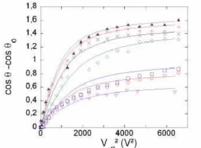
Saturation
Equation (5) enlightens the conditions concerning the minimum voltage required for droplet displacement. We will now look at the EWOD saturation effect. Given equation (4), total wetting seems possible. Experimentally, however, a saturation phenomenon is observed past some voltage value. Figure 5 gathers experimental results for various liquids. For weak voltages, variation of the angle’s cosine is proportional to the square of the tension (eq 4). For stronger voltages,
θ
cos stops increasing and stabilizes at a saturation angle value θ
cos . The model can be empirically improved by using a
hyperbolic)tangent model (eg: a Langevin equation) [22], resulting in Equation (6) which may be called the modified Lippmann Young equation :
(
)
− − = − ) cos cos 2 3 ) cos (cos cos cos 0 2 0 0 θ θ γ θ θ θ θ (6)where ( )=coth −1 is the Langevin function and
θ
is the saturation angle. A good correlation between experimental results and theory is validated in figure 5.Figure 5: Electrowetting behaviour for various liquids. Points correspond to experimental results;
curves are derived from the modified Lippmann Young equation.
A number of conflicting hypothesis are available in the literature to explain the saturation effect. One hypothesis
concerning saturation introduces a liquid)solid surface tension
γsl(V)=γsl)fethat can not become negative in equation (1) [23,
24]. Thus, introducing a limitation to fe which is necessarily smaller thanγsl. Another hypothesis, from a more experimental
point of view correlates saturation to either satellite droplet ejection phenomena [25], or ionization in the vicinity of the triphasic line [26]. This shows that the variable surface capacity mechanical model is not sufficient to explain saturation. Therefore it is necessary to better describe EHD mechanisms within the droplet interface.
Let us imagine a strongly conducting droplet, electrically insulated, immersed in a perfectly insulating fluid with permittivityε. The droplet is equipotential, and the stresses of electrostatic origin are reduced to the electrostatic pressure :
2
2 1ε
= (7)
where depicts the electrostatic field perpendicular to the interface. Electrostatic pressure is mostly concentrated in the vicinity of the triphasic line on a height similar to the thickness of the dielectric layer [27, 28]. This very high value of the local electrostatic field may cast doubts on the equipotential droplet hypothesis. As such, in [29], saturation is studied by taking into account current leaking through the dielectric.
The diversity of explanations show that saturation phenomena remain poorly understood. Among the reasons behind this statement is the observation that most of the EHD mechanisms are concentrated within a zone for which modelling is most difficult (i.e. the triphasic line).
Figure 6: Left: Example of flow characterized by chaotic curls during droplet handling. Right: Visualisation of 4 vortices in a droplet positioned on
two electrodes. Top: Picture top view, bottom: side view of diagram.
EHD tangential effect at droplet interface
The emergence of convective motion has been observed in droplets under EWOD actuation [30]. Figure 6 (left) shows an example of a droplet containing fluorescent molecules seen from above. As the droplet moves, we observe the formation of “volutes” or “curls”, suggesting intense internal agitation within the droplet. Even though thermal or chemical Marangoni effects must be taken into account, it is necessary to look at the impact of the electrostatic field on tangential stress. Taylor in particular [31] has shown that cellular convective flow appears in a droplet positioned in an electrostatic field. In
V 0,V
some configurations we were able to obtain a flow structure strongly reminiscent of those presented by Taylor. Considering a droplet positioned on two electrodes of unequal potentials, two pairs of counter)rotating cellular convective flows were observed (fig 6, right). The emergence of stable vortices within a motionless droplet is a noteworthy fact offering opportunities for fluidic functionality like mixing.
Taylor explained these convective flows by calculating the Maxwell stress tensor applied on the interface [31]. Considering a regular interface separated by two immiscible fluids 1 and 2, each fluid having a finite permittivity ε and resistivity σ, the Maxwell stress tensor allows for the computation of the perpendicular and tangential stress components and :
[
] [
2]
1 2 1 1 2 2 2 2 2 2 1 2 1 − − − =ε
ε
(8) − = (9)where and stands for the tangent and perpendicular electrostatic field components at the interface and for the surface charge density. Equation (9) shows that the tangential stress exists only if the droplet is not equipotential.
The model which considers a droplet as an insulated conductor immersed in a perfectly insulating medium is, thus, a questionable hypothesis. The emergence of a vortex in a droplet proves indeed that it is not equipotential, as confirmed by the saturation effect explanation described by [25, 26, 29].
To summarize, electrowetting is an efficient actuation mode with numerous applications (see for instance a complete state of the art description described by Mugele et al. [32]). We have seen that a simple mechanical model is on one hand sufficient for understanding the general electrowetting behaviours on the other hand it is deficient when explaining complex phenomena such as saturation or electro convection. For better understanding, more complex models need to be developed; in particular they should consider the drop as a non equipotential object.
Figure 7: Diagram and photo of Open EWOD chip. 4 TECHNOLOGIES
EWOD technology is usually based on collective and well known micro technology processes involving successive
deposition, photolithography and etching steps. A 3000 Å thick layer of gold is deposited on an insulating substrate such as glass or silicon oxide. The gold electrodes are etched and covered with a dielectric layer of silicon nitride 3000 Å thick. The surface is made hydrophobic by depositing a fine layer of Dupont AF teflon of a few hundred nanometers. Chips are diced and electrically packaged on a printed circuit board (fig. 8). This technology is simple and does not require great dimensional precision for droplets larger than a few dozen nl. Technology similar to those used for printed circuits may be considered [33]. Two packaging categories coexist, closed and open EWOD.
Open EWOD.
The droplet has a hemispherical shape with no cover and simply lies on the EWOD active support [34]. Indeed as suggested in figure 2, it is possible to directly apply a potential to the droplet thanks to a direct electrical contact that can be an electrical wire tensioned over the substrate (figure 7). This wire or catenary [30] is both a guide and an electrode guiding the droplet like a tramway cable. The catenary is either directly included in the substrate [33] or is added afterwards by wire bonding using a 30Om gold wire with no great positioning precision constraint.
The open configuration is beneficial from a simplicity and low cost fabrication standpoint. Furthermore, an open system allows the use of classic reagent distribution methods, such as a simple pipette or dispensing robot for simplified utilization. The droplet spherical shape has the lowest possible wetting area for a given droplet volume,. Water drops ranging from 0.5 to 2 Ol may be manipulated on 800Om by 800Om electrodes size. In comparison, a 2Ol volume in a channel would require much more space, resulting in large and costly chips. However, droplet dispensing, or splitting is usually difficult to perform on an open system unless liquids with very low surface tension are used, such as ionic liquids [22].
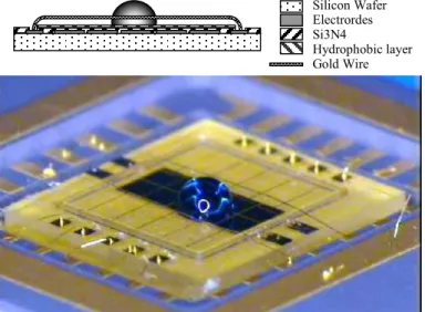
Closed EWOD
This is the most widespread configuration, where droplets are constrained within two planes. Open systems require more sophisticated technological processes and packaging methods. The technology put forth on figure 8 involves a 100Om gap implemented by a dry photosensitive film of Ordyl. The Ordyl walls are also used to isolate different chip zones such as reservoirs, reaction zones or to limit on chip droplet cross talks. The cover is made of a polycarbonate plate coated with ITO (indium tin oxide) used as a transparent conductive layer, and a hydrophobic Teflon layer. The cover is drilled to form reservoir wells allowing reagent filling of the chip.
The plate cover may be glued or mechanically pressed on the EWOD chip. Unlike channel microfluidics it is not necessary to have a waterproof assembly between the two plates. Within a closed configuration, the droplet can be compared to a flat disk with a small aspect ratio defined by the chip gap (height between the cover and the chip) on the electrode side. Because of this small aspect ratio, a closed configuration allows huge droplet deformations, essential for performing the main fluidic functions like droplet dispensing or splitting [35)37]. To achieve a complete integration of a protocol, a closed configuration is usually a better alternative.
Silicon Wafer Electrordes Si3N4
Hydrophobic layer Gold Wire
Figure 8: Diagram and photo of closed EWOD chip. Mixed system
Both open and closed solutions are not incompatible. Under some conditions [38] one may combine an open and a closed system with droplets transiting from one zone to another. It is easy to imagine multiple hybrid systems, a recent example of which can be seen in figure 9.
This device integrates not only a closed and open EWOD system but also a zone allowing a vertical droplet displacement toward a third substrate (high substrate) placed within a few droplet diameters away. The high substrate is comprised of a supplementary third electrode beside the catenary and the electrode array used for EWOD actuation [39]. Applying a tension between the catenary and that high electrode allows for droplet take)off via electrostatic forces. The droplet may stay on the high substrate or be brought back on the lower substrate for a new manipulation via electrowetting.
Figure 9: Diagram and photo of a hybrid EWOD chip. Photos on right: Vertical motion between top and
bottom plate.
In the device, the droplet is dispensed in a confined system, then moves to an open system and finally takes off in a vertical movement toward the high substrate. Even though, this vertical motion is not based on EWOD actuation it appears complementary, adding functionalities: for instance reaction or reagent storage on a higher plane, or droplet oscillation between two substrates of different temperatures inducing thermal cycling of the droplets. In the same way, coupling EWOD and channel based microfluidics may help for integrating new applications.
5 FLUIDIC FUNCTIONS
Fluidic functions will be presented using the chip in figure 8, whose diagram can be found in figure 10. The chip is made of 3 zones. Zone A is composed of a loading and dispensing reservoir and is used as the interface between the outer world and the chip. Zone B was developed for storage and dispensing reagents or intermediate reactions. Zone C consists in a bus for moving droplets around from one functional zone to another. The bus electrodes are 800Om by 800Om. The chip’s dimensions are 13mm by 13mm. Actuating tensions are 60Vrms at a 3 kHz frequency. The chip is initially filled with silicon oil, preventing droplet evaporation and providing lower interface tension which increases the electrowetting effect (cf eq 4). The presence of a permanent thin oil film between the droplet and the chip surface limits absorption of molecules on the chip surface minimizing contamination risks and improving displacement of complex biological products [35].
Figure 10. EWOD chip Layout (red circles correspond to reservoir wells drilled in the cover ) Dispensing:
Dispensing a droplet from the reservoir is done in two steps. To start with, the reagent or sample is placed on a reservoir electrode. In step one, the liquid is stretched by activating a number of electrodes in order to form a liquid finger while the reservoirs electrode is deactivated. In step two, the liquid finger is pinched by deactivating one of the stretching electrodes (shutoff of electrode labelled e3 in figure 11). For the pinching to be fully efficient and separate the dispensed droplet on the dispensing electrode (labelled e4), it is necessary B : Storage and dispensing reservoirs C Bus A : Loading and dispensing reservoir Silicon Wafer Electrodes Polycarbonate Si3N4 Hydrophobic layer Spacer
to pump back the liquid by activating the reservoirs electrode. Droplet volume is thus primarily defined by the dispensing electrode surface multiplied by the gap value.
When working with appropriate activating tensions and gap values it is possible to ensure that the new dispensed droplet precisely covers the dispensing electrode e4, yielding reproducible droplet volume independent of the liquid properties (viscosity, presence of surfactant,….).
Figure 11: Diagram and photos of droplet dispensing. e1: Electrode reservoir. e3: Shutoff electrode. e4:
Dispensing electrode.
The smaller the aspect ratio (ratio of the gap over the size of the electrode), the easier it is to reproducibly and precisely fill the dispensing electrode volume. On figure 11, the square topology of the activated dispensing electrode generates a square droplet. This important drop deformation enables the drop to completely cover the dispensing electrode, and thus, reproducible dispensing.
The chips that we have designed have 800Om X 800Om square electrodes and a 100Om gap. The resulting 0.125 aspect ratio is smaller than usually reported in the literature and improves reproducibility.
Figure 12. Chip filling and on-chip dispensing. (a) Shifted well is filled with a pipette, (b) A well electrode pumps the reagent from the well to the reservoir, (c) A star shaped electrode attracts the liquid towards the bus. (d) Droplet dispensing
Reagent or sample filling of the chip is the most sensitive step. Indeed we have noticed that direct droplet dispensing from a well is not usually reproducible, confirming observations reported in [40]. This may be explained by uncontrolled fluctuations of liquid pressure in the well.
Reproducibility is much better if the reagent or sample is loaded with a shifted entry well as described in figure 12. This reproducible alternative allows one to be sure that the liquid in
the reservoir is not connected with the liquid in the well. An additional improvement seen in figure 12 is related to the star shape of the reservoir electrode. This allows constant positioning of the reagent or the sample in the dispensing zone close to the stretching electrodes.
For 67 nl droplets dispensed in zones A, we have obtained a CV of 0.85% and for 28 to 40 nl droplets dispensed from various reservoirs in zone B, CVs were below 3%. These excellent results show that the level of accuracy reached is most adequate for using EWOD actuated dispensing in many applications.
Coalescing and mixing
Mixing droplets merely consists in joining the droplets on the same electrodes, where they automatically coalesce. To achieve a homogenous liquid, the new liquid should be agitated by EWOD displacement. Figure 13 shows a motion picture of droplet movement leading to the fusion of two 64 nl droplets, one of which containing fluoresceine. We notice that each move induces « stirring » in the droplet. This stirring is characterized by very strong shear flow on the droplet side. Following the fluorescence during displacements show that liquid placed at the tail end of the droplet is found in front in just two moves. This rapid mixing is due to intense fluid convection on the lateral sides of the droplet, along the water) oil interface. The stirring may be generated by the formation of two vortices rotating in opposite directions. It is important to notice that these vortices rotate in a direction counter to the direction of droplets circulating in channels when subject to hydrodynamic forces only [41].
Paik et al.[37] reports on a detailed study on EWOD base mixing where an optimum was reached for an aspect ratio of 0.4 on a square loop displacement. A minimum time of 2.9 seconds was measured at a 16Hz motion frequency, for a mix of two 1.4Ol droplets. In our set up, the 0.125 aspect ratio, along with a linear bus, is not optimal for a fast mix. Using the same procedure as Paik, we have characterized mixing time with our small aspect ration for back and forth displacements.
Figure 13. (a) EWOD mixing within linear movement. (b) Flow diagram (c) Comparison with droplet based
channel microfluidics
Our results show that fifteen moves are needed to obtain 95% homogeneous mixing corresponding to 15 seconds for 1Hz in motion frequency. This is acceptable for many
e1 e2 e3 e4
a
b
c
d
Nb of move 1 2 3 4 5 6 7 ….a
applications. If mixing time needs to be reduced, motion frequency can be increased by lowering the oil viscosity. Using Dimethylsiloxane with 1.39 mPas viscosity, from Gelest Inc.),
we were able to reach 2 second mixing times.
Chip architecture
Development time for chip design should be minimized by constructing chips or architectures as generic as possible. A first approach uses an electrode matrix of N lines and M columns. However the number of electrical connections becomes quickly very high with N x M connections. An alternative is to make an active matrix of TFT. Actuation tensions for EWOD are usually greater than a few dozen volts and as such prevent direct uses of standard microelectronics technologies implemented in standard TFT. Two other alternatives consist of either an original EWOD actuation system based on optical switching [42] or an orthogonal overlay of two substrates [18], each with a network of parallel lines.
The approach we have chosen is based on a bottom)up microelectronic architecture. Each elemental function: movement, mixing, droplet dispensing, reactive zone, etc … is carefully validated, optimized, and standardized. A basic design library, specific to each elementary fluidic function, is optimized and validated. Designing a new chip for a given application, then, amounts to assembling basic designs required by the protocol. The chip shown on figure 11 follows this logic. Generalizing, chips are organized within three zones:
Fluidic In /Out interface allowing buffer samples, and reagents injection, and collection of analytical products.
A set of secondary reservoirs allowing storage of reagents, reaction preparation (mixing, dilution, incubation …) or intermediary reactions incubation or storage.
These are application)specific zones implementing temperature control, electrical or optical detection, separation or concentration functionalities via magnetic beads. These zones communicate via buses made of a line of electrodes, with straight, coiled, or looped paths.
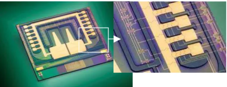
Figure 14. EWOD fluidic processor. Zooms on the bus and the multiplex reservoirs.
Complex chips
As chip complexity increases, adding some amount of redundancy within electrodes is necessary in order to reduce packaging costs and minimize the number of electrical switches. From a technological standpoint, a second electrical level can be necessary for interconnecting electrodes, in order to minimize the number of electrical switch.
A first solution to decrease the number of electrical switches for a bus consists in interconnecting electrodes with a period of 3, 4 or 5. With only 5 relays, for instance, 64 to 128nl droplets may be moved on an 800Om by 800Om electrode.
Another possibility consists in multiplexing the electrodes used for droplet dispensing and displacement between the storage reservoir and the bus. It was shown in [43] that it is possible to address 2n reservoirs with only n relays. Each reservoir is addressed by an n)digit binary number. (eg 8 relays may control 128 reservoirs). A 16 reservoir (n=4) example is shown in figure 14.
With this architecture we are able to conceive chips integrating a large number of already validated elementary designs, while keeping the number of switches reasonably low (between 16 and 48 relays). However, reducing the number of electrical switches renders chip manufacturing a little more complex requiring a second electrical level but still remains far simpler to realize than TFTs or CMOS.
6 APPLICATIONS
Recent publications in the field point towards a multitude of applications. In biological studies, EWOD technology has been used for chips involved in the preparation and identification of proteins analyzed by matrix)assisted laser desorption/ionization mass spectrometry (MALDI)MS) [44]. In molecular biology, we can find examples of PCR [43] and enzymatic DNA repair [45]. Ionic liquids were also used in applications of chemical synthesis [46] associated with EWOD actuation. The various studies show the versatility of EWOD for the displacement of a variety of biological components, buffer, biological fluids, …
As an example of biological protocol integration, we have worked on a human SNP (Single Nucleotide Polymorphism) genotyping based on PCR . Following the previously described droplet)based architecture of a chip, a DNA sample is injected and divided into small droplets. Each droplet is then mixed with another droplet containing the specific SNP)PCR mix. On)line detection of genotyping reactions is done using a microscope equipped with a fluorescence detector. Amplification was performed using human placental DNA samples corresponding to 10 DNA copies in 64 nl for on chip reactions and 160 copies in 10Ol for the reference microtube reactions. Taqman Amplitaq mix (Applied Biosystem) was used for the PCR reagents. The thermo cycling was obtained by placing a Peltier plate under the EWOD chip. The PCR cycles consisted of two 30 second 60 and 92 °C plateau with 30 seconds ramping.
The genotyping reaction shown in Figure 15 is a homozygote DNA sample. At 40 cycles, only Fam is visible (drop+). The negative control, a reaction without DNA, does not show any fluorescence intensity indicating on one hand the specificity of the reaction and on the other the lack of cross contamination. The fam fluorescence intensity at different cycles is shown in Figure 15d. The droplet)based PCR performed in 60 nl is compared to a standard microtube reaction of a volume of 10Ol performed on a standard PCR thermocycler ((MX3005P Stratagene). In both cases, the fluorescent intensity increases after 30 cycles, showing similar cut off cycles. After amplification, the PCR products obtained on chip were analysed by gel electrophoresis (Agilent, BioAnalyser 2100). Figure 15(c) shows that the amplification is specific with good yields.
(a) (b)
(c) (d)
Figure 15: PCR validation in a 64 nl droplet. Picture of a fluorescent droplet: (a) Fam and (b) Vic, after 40 cycles. (c) Droplet analysis on the bioAnalyser. (d) Fluorescence intensity of Fam at various number of
cycles – comparison is made to a standard experiment performed in a microtube.
These results validate droplet)based PCR under EWOD actuation and show the robustness of the system with small DNA copy numbers. The system can be easily improved by reducing PCR cycling time to 15 minutes, by integrating the heating on chip.
Current development involves integrating sample preparation steps to the above mentioned PCR system, addressing the challenge of implementing a complete protocol. Y.Zhao, S.K. Cho [47] report on a system where displacement of liquids using EWOD actuation can be used for chip cleaning and airborne sample collection. All these applications show that fully auto mated portable monitoring systems for airborne micro organisms and environmental control can be envisaged.
6 CONCLUSION
In summary, digital microfluidic coupled with EWOD actuation appears very promising since all the fluidic functions can be achieved by EWOD actuation, simplifying integration of complex protocols. This is due to the fact that fluidic movements are accomplished electronically without pumps or any other moving parts. Fabrication of micro)components of an EWOD system is based on a simple technology easily manufacturable. The choice of chip surface (good dielectric property and weak hysteresis) remains key, given that it is the main driver for good actuation performances.
One of the main advantages of this approach is its modularity, as it can be constructed like a puzzle, each element of the puzzle being a validated design of a fluidic elementary function. The elementary design based architecture we have chosen allows us to introduce the concept of a fluidic EWOD microprocessor. Thus we can quickly realize EWOD chips for a variety of applications even when a large number of elementary fluidic functions are necessary.
Research needed includes on one hand sharper theoretical models in order to understand, improve upon, and better exploit EHD phenomena linked to electrowetting. Developments, on the other hand, must be pursued to integrate new fluidic functionality. One should not, in that area, exclude the possibility of coupling EWOD with other types of microfluidics such as channel)based for instance. On a final note, our current objective consists in developing fully integrated systems including instrumentation, the microfluidic chip and the protocol for complex applications in biology and chemistry.
Altough EWOD seems very promising; we believe that it is in merging several microfluidic methods that the integration difficulties will be overcome.
ACKNOWLEDGMENTS
This work was funded by the French research ministry.
REFERENCES
[1] A. Manz, N. Graber, and H. M. Widmer, "Miniaturized Total Chemical) Analysis Systems ) a Novel Concept for Chemical Sensing,"
, vol. 1, pp. 244)248, 1990.
[2] D. J. Harrison, K. Fluri, K. Seiler, Z. H. Fan, C. S. Effenhauser, and A. Manz, "Micromachining a Miniaturized Capillary Electrophoresis)Based Chemical)Analysis System on a Chip," , vol. 261, pp. 895)897, 1993.
[3] A. R. Kopf)Sill, "Successes and challenges of lab)on)a)chip," !, vol. 2, pp. 42n)47n, 2002.
[4] R. H. Liu, J. N. Yang, R. Lenigk, J. Bonanno, and P. Grodzinski, "Self) contained, fully integrated biochip for sample preparation, polymerase chain reaction amplification, and DNA microarray detection," "
", vol. 76, pp. 1824)1831, 2004.
[5] J. Lee and C. J. Kim, "Surface)tension)driven microactuation based on continuous electrowetting," # $ " , vol. 9, pp. 171)180, 2000.
[6] M. G. Pollack, R. B. Fair, and A. D. Shenderov, "Electrowetting)based actuation of liquid droplets for microfluidic applications," !!
" , vol. 77, pp. 1725)1726, 2000.
[7] W. N. Gill and Sankaras.R, "Exact Analysis of Unsteady Convective Diffusion," % " "
$ " , vol. 316, pp. 341)&, 1970. [8] H. A. Stone, A. D. Stroock, and A. Ajdari, "Engineering flows in small
devices: Microfluidics toward a lab)on)a)chip," % & ' $ , vol. 36, pp. 381)411, 2004.
[9] T. Thorsen, R. W. Roberts, F. H. Arnold, and S. R. Quake, "Dynamic pattern formation in a vesicle)generating microfluidic device," " % & , vol. 86, pp. 4163)4166, 2001.
[10] D. R. Link, S. L. Anna, D. A. Weitz, and H. A. Stone, "Geometrically mediated breakup of drops in microfluidic devices," " % &
, vol. 92, pp. ), 2004.
[11] Y. C. Tan, J. S. Fisher, A. I. Lee, V. Cristini, and A. P. Lee, "Design of microfluidic channel geometries for the control of droplet volume, chemical concentration, and sorting," !, vol. 4, pp. 292)298, 2004.
[12] J. Sudor, Y. Fouillet, N. Sarrut, I. Chartier, P. Peltie, and A. Gruss, "Microfluidic device for high)throughput genotyping," ( % ) * , pp. 53)57, 2003.
[13] T. Thorsen, S. J. Maerkl, and S. R. Quake, "Microfluidic large)scale integration," , vol. 298, pp. 580)584, 2002.
[14] P. R. C. Gascoyne, J. V. Vykoukal, J. A. Schwartz, T. J. Anderson, D. M. Vykoukal, K. W. Current, C. McConaghy, F. F. Becker, and C.
9000.00 11000.00 13000.00 15000.00 17000.00 19000.00 21000.00 10 20 30 40 drop) drop+ tubectrl + tubectrl ) drop+ Drop) Fam Vic Drop) drop+ Cycle nb Fluorescence intensity
Andrews, "Dielectrophoresis)based programmable fluidic processors," !, vol. 4, pp. 299)309, 2004.
[15] A. L. Yarin, W. X. Liu, and D. H. Reneker, "Motion of droplets along thin fibers with temperature gradient," # !! " , vol. 91, pp. 4751)4760, 2002.
[16] I. F. Lyuksyutov, D. G. Naugle, and K. D. D. Rathnayaka, "On)chip manipulation of levitated femtodroplets," !! " , vol. 85, pp. 1817)1819, 2004.
[17] A. Wixforth, "Acoustically driven planar microfluidics," ! $ , vol. 33, pp. 389)396, 2003.
[18] S.)K. Fan, C. Hashi, and C.)J. Kim, "Manipulation of multiple droplets on N/spl times/M grid by cross)reference EWOD driving scheme and pressure)contact packaging," presented at Micro Electro Mechanical Systems, 2003. MEMS)03 Kyoto. IEEE The Sixteenth Annual International Conference on, 2003.
[19] B. Berge, "Electrocapillarity and Wetting of Insulator Films by Water,"
! % * * ) , vol. 317, pp. 157)
163, 1993.
[20] Y. Fouillet, H. Jeanson, I. Chartier, A. Buguin, and P. Silberzan, "Moving droplets with a micro catenary," ( % ) * , pp. 37)42, 2003.
[21] K. A. Brakke, "The surface evolver and the stability of liquid surfaces,"
! + % " "
$ " , vol. 354, pp. 2143)
2157, 1996.
[22] J. Berthier, P. Clementz, O. Raccurt, D. Jary, P. Claustre, C. Peponnet, and Y. Fouillet, "Computer aided design of an EWOD microdevice,"
, " , vol. In Press, Corrected Proof. [23] A. Quinn, R. Sedev, and J. Ralston, "Contact angle saturation in
electrowetting," # " " , vol. 109, pp. 6268) 6275, 2005.
[24] V. Peykov, A. Quinn, and J. Ralston, "Electrowetting: a model for contact)angle saturation," " , vol. 278, pp. 789)793, 2000.
[25] F. Mugele and S. Herminghaus, "Electrostatic stabilization of fluid microstructures," !! " , vol. 81, pp. 2303)2305, 2002. [26] M. Vallet, M. Vallade, and B. Berge, "Limiting phenomena for the
spreading of water on polymer films by electrowetting," ! " # , vol. 11, pp. 583)591, 1999.
[27] K. H. Kang, "How electrostatic fields change contact angle in electrowetting," , vol. 18, pp. 10318)10322, 2002. [28] A. G. Papathanasiou and A. G. Boudouvis, "Manifestation of the
connection between dielectric breakdown strength and contact angle saturation in electrowetting," !! " , vol. 86, pp. ), 2005.
[29] B. Shapiro, H. Moon, R. L. Garrell, and C. J. Kim, "Equilibrium behavior of sessile drops under surface tension, applied external fields, and material variations," # !! " , vol. 93, pp. 5794) 5811, 2003.
[30] Y. Fouillet, H. Jeanson, D. Jary, and C. Vauchier, "Moving droplets with microcatenaries," presented at Micro Total Analysis System, Squaw Valley, California, USA, 2003.
[31] G. Taylor, "Studies in Electrohydrodynamics .I. Circulation Produced in a Drop by an Electric Field," % " "
$ " , vol. 291, pp. 159)&, 1966. [32] F. Mugele and J. C. Baret, "Electrowetting: From basics to applications,"
# " $ , vol. 17, pp. R705)R774, 2005. [33] P. Paik, V. K. Pamula, M. G. Pollack, and K. Chakrabarty, "Coplanar digital microfluidics using standard printed circuit board," presented at Micro Total Analysis Systems, Boston, USA, 2005.
[34] M. Washizu, "Electrostatic actuation of liquid droplets for microreactor applications," ) + ) " !! , vol. 34, pp. 732)737, 1998.
[35] V. Srinivasan, V. K. Pamula, and R. B. Fair, "An integrated digital microfluidic lab)on)a)chip for clinical diagnostics on human physiological fluids," !, vol. 4, pp. 310)315, 2004. [36] S. K. Cho, H. J. Moon, and C. J. Kim, "Creating, transporting, cutting,
and merging liquid droplets by electrowetting)based actuation for digital microfluidic circuits," # $ " , vol. 12, pp. 70)80, 2003.
[37] P. Paik, V. K. Pamula, and R. B. Fair, "Rapid droplet mixers for digital microfluidic systems," !, vol. 3, pp. 253)259, 2003. [38] J. Berthier, P. Clementz, J. M. Roux, F. Y., and C. Peponnet, "Modeling
microdrop motion between covered and open regions of EWOD microsystems," presented at Nanotech 2006, Boston, USA, 2006.
[39] J. M. Roux, Y. Fouillet, and J. L. Achard, "Handling droplet in 3 dimensions for lab)on)chip applications," presented at Micro Total Analysis Systems, 2004.
[40] R. B. Fair, V. Srinivasan, H. Ren, P. Paik, V. K. Pamula, and M. G. Pollack, "Electrowetting)based on)chip sample processing for integration microfluidics," presented at IEEE Inter. Electron Devices Meeting (IEDM) 2003, 2003.
[41] H. Song, J. D. Tice, and R. F. Ismagilov, "A microfluidic system for controlling reaction networks in time," &
) , vol. 42, pp. 768)772, 2003.
[42] P. Y. Chiou, H. Moon, H. Toshiyoshi, C. J. Kim, and M. C. Wu, "Light actuation of liquid by optoelectrowetting,"
" , vol. 104, pp. 222)228, 2003.
[43] Y. Fouillet, D. Jary, A. G. Brachet, C. Chabrol, J. Boutet, P. Clementz, D. Lauro, R. Charles, and C. Peponnet, "Design and validation of a complex generic fuidic microprocessor based on ewod droplet for biological applications," presented at Micro Total Analysis Systems, Boston USA, 2005.
[44] A. R. Wheeler, H. Moon, C. A. Bird, R. R. O. Loo, C. J. Kim, J. A. Loo, and R. L. Garrell, "Digital microfluidics with in)line sample purification for proteomics analyses with MALDI)MS," " ", vol. 77, pp. 534)540, 2005.
[45] D. Jary, A. Chollat)Namy, F. Y., J. Boutet, C. Chabrol, C. G., G. D., and C. Peponnet, "DNA repair enzyme analysis on EWOD fluidic
microprocessor," presented at Nanotech 2006, Boston, USA, 2006. [46] P. Dubois, G. Marchand, Y. Fouillet, C. Peponnet, C. Chabrol, J.
Berthier, and M. Vaultier, "Ionic liquid droplet as microreactor displaced by electrowetting on dielectric," presented at Micro Total Analysis Systems, Boston, USA, 2005.
[47] Y. Zaho and s. K. Cho, "Microparticle sampling by electrowetting) actuated droplet sweeping," !, vol. 6, pp. 137)144, 2006.