Design and Testing of a
Stewart Platform Augmented Manipulator
for Space Applications
by
Terrence W. Fong
B.S., Massachusetts Institute of Technology (1988)
Submitted in Partial Fulfillment of the Requirements for the Degree of
Master of Science in
Aeronautics and Astronautics
at the
Massachusetts Institute of Technology
June 1990
© Massachusetts Institute of Technology, 1990
Signature of Author
Department o~ ronautics and Astronautics
May 11, 1990
Certified byAccepted by
Professor David L. Akin Thesis Supervisor Slpartment of Aeronautics and Astronautics
- \, Professor Harold Y. Wachman
MASSACHUSEiTS INSTITUTE
OF TECHNOLOGY
JUN
19 1990
Chairman, De Graduate Committee
Department of Aeronautics and Astronautics
Design and Testing of a
Stewart Platform Augmented Manipulator
for Space Applications
by
Terrence W. Fong
Submitted to the Department of Aeronautics and Astronautics on May 11, 1990 in partial fulfillment of the requirements for the degree of Master of Science in Aeronautics and Astronautics
Abstract
An innovative nine degree-of-freedom robotic manipulator intended for neutral buoyancy space simulation research has been developed. The manipulator design specifications were driven by two primary goals; to duplicate and surpass the operational characteristics of the Shuttle Remote Manipulator System (SRMS) and to serve as a robust, neutral-buoyancy positioning system. The ability to provide fine tip positioning as well as large force production capability was realized by decoupling the system design into a three degree-of-freedom, revolute joint, manipulator arm augmented by a six degree-of-freedom, parallel-link, micromanipulator. Hybrid pneumatic/hydraulic actuators were developed to overcome neutral buoyancy constraints and to satisfy safety considerations. Finally, a variety of joint-based control schemes and Cartesian trajectory planning methods were implemented and studied.
This research was funded by the NASA Office of Technology (NASA Grant NAGW-21).
Thesis Supervisor:
Aeronautics and Space
Professor David L. Akin
Acknowledgements
Two years ago as a fledgeling graduate student, I approached Dave and asked "What would be a really neat thing to build?" He replied, "Ummm, well, I've got an idea for a pneumatic positioning arm. It would be like the big arm down at Marshall [Space Flight Center] but much stronger. And I figure that we can make it strong enough to use in
one-g, so we can take it to freshman open houses and tap people on the shoulder with it."
At the time I had no idea what to call the arm. A long string of attempts at naming ensued with such dubious acronyms as Big Large Arm Hopefully (BIAH) and
Pneumatically Actuated Robotic Manipulator Equipped with a Synergetically Active Network (PARMESAN). After many months, and uncountable groans from everyone in
SSL, I finally decided the "big arm" would be called the Stewart Platform Augmented
Manipulator, and thus, SPAM was born. Where the inspiration for SPAM came from, I am
uncertain. Of course there is the processed meat product of the same name to consider. But I doubt that. There is alternatively my dear friend Cindy Shen, who picked up the nickname "SPAM" when she was a freshman. But I have my doubts about this also. Lastly, there is the skit by Monty Python ("Spam, spam, spam...") involving a restaurant that only serves SPAM. This MAY be where "SPAM" originated, but then again, one can never be sure...
There are a great number of people that I feel deserve my expressed appreciation and gratitude. First and foremost, I would like to thank Professor David Akin for his encouragement, support, and timely advice over the past few years. I am convinced that the prospect of working with Dave was the primary factor which drove me to pursue another degree at MIT. All that I have learned and gained during the past two years, I feel I owe to
him. It is my sincere hope that we will be able to work together again in future days.
Second, I am indebted to all the undergraduates who worked on SPAM. Paul "Jello" Duncan, deserves endless acclamations since he toiled long hours building most of the hardware and being the "SPAM Diver". I could not have asked for a more capable "right-hand man". Cecelia "Too Tall" Park should be given an award for the amazing amount of foam and fiberglassing she had to endure under my dubious guidance. I cannot thank her enough for her unwavering commitment and dedication. Paul "Moonbeam" Stach will hopefully realize his ambition of "going to the moon on a craft of his own design", but until then, I hope he will take pride in the most excellent parts of SPAM (especially the "Stach Wrench") that he built. It was great fun and a tremendous pleasure to have worked with a fellow Illini! Additionally, I owe thanks (and probably several apologies for waking
her) to Beth "Starlight" Kader, the "Bonus UROPer". I had no idea that hiring "Moonbeam" was a package deal, but I appreciate all of Beth's help at Pool Tests. Finally, gratitude is also due to Wisdom Franchot Coleman, Ronke Olabisi and Jen Tran.
To Professor Harold "Sandy" Alexander, I extend my heartfelt appreciation for his constructive suggestions, weekend shop supervision, and for introducing me to the Advanced Missions Group at NASA-Ames. To Ping Lee, I apologize profusely for the stream of inundating purchase orders and receipts that I constantly poured on her desk. Acknowledgement must additionally be given to Al Shaw, Earle Wassmouth, and Don Weiner for having the courtesy to deal with myself and everyone associated with SPAM.
To the community that is the "SSL family", my thanks go: to Rich Patten for teaching me everything about pneumatics; to Karl "Killer" Kowalski for always being amusing and wanting a good argument; to Jud "Cowardly Lion" Hedgecock for his friendship since Unified; to Ender St. John-Olcayto "Smythe" for being a great roommate, friend and confidant; to Ella "Mrs. Smith" Atkins for just being Ella (even though she decided my name should be "Fong Unit") and for always telling me "that's nice, dear"; to Rob Sanner-Blah for his invaluable advice in computer science and fabulous cookies; to Sayan "Interview-Man" Chakraborty for being an active member in the "Sleep 'Til Noon or Preferably Later Club" (may he always have a "birdhouse in his soul"); to Sam "Zorrrrrrrrrtech" Druker for lending me Young M.C.'s Stone Cold Rhymin' and for sharing my disgust of Microsoft products; to Kurt "Smut-Man" Eberly for always amusing me with his "Hans and Franz" imitation; to Matt "Mattress" Machlis for throwing a frisbee (and for splattering me all over the slopes at Cannon Mt.); and to Russ "Fluffy" Howard for having the reference books on anything and everything I needed.
Finally, my thanks to my family and friends who have made the past two years the best years of my life. To my parents for always giving me the encouragement and support to do whatever I wanted to do my entire life, I will always be deeply indebted. I only hope that they know how much their love has meant to me. To my brother Tim, and sister Tammy, thanks for being silly and asking amusing questions. To Brian, Cindy, Ellen, Eric, Mini, Ryo, and Tex, thanks for everything. To Eriko, for being my friend, fellow "strobophobe" and for always amusing me. Most of all, thanks to Jessica for being the most wonderfully caring person in the world, for talking with me about anything and everything, and for giving me companionship and love.
"I didn't expect a kind of Spanish Inquisition."
"NOBODY EXPECTS THE SPANISH INQUISITION!!! Our chief weapon is surprise..
. surprise and fear... fear and surprise ... our two weapons are fear and surprise ...
and ruthless efficiency. Our three weapons are fear and surprise and ruthless efficiency and an almost fanatical devotion to the Pope ... Our four ... no ... amongst our weapons are such elements as fear, surprise ... (arrrrrrrrrrgh) I'll come in again ... "
Table of Contents
Introduction
14
1.1 SSL Research Background 14 1.2 The SRMS Simulator 15 1.2.1 Summary of the SRMS 15 1.2.2 SRMS Simulator Characteristics 161.3 Motivation for Research 17
System Design
19
2.1 Design Goals 19
2.2 The Stewart Platform Augmented Manipulator 20
2.2.1 SPAM Concept Development 20
2.2.2 3-DOF Manipulator Design Specifications 22
2.2.3 6-DOF Stewart Platform Specifications 23
Manipulator Arm
25
3.1 Manipulator Kinematics 25 3.1.1. 2-Link Manipulator 27 3.1.1.1. Forward Kinematics 28 3.1.1.2. Inverse Kinematics 29 3.1.2. 3-Link Manipulator 29 3.1.2.1. Forward Kinematics 32 3.1.2.2. Inverse Kinematics 323.2. Manipulator Control Schemes 33
3.2.4. Closed-Loop Tip Control 37
3.2.5. Inverse Jacobian Controller 38
3.3. Revolute Joint Design & Testing 39
3.3.1. Development of Neutral Buoyancy Actuators 39
3.3.2. Revolute PHAD-A 41
3.3.3. Revolute PHAD-B 47
3.3.4. Position Sensor 52
3.3.5. Joint Servo Control 53
3.3.5.1. Position Servo Design & Testing 53
3.3.5.2. Velocity Servo Design & Testing 57
3.4. SPAM Manipulator Hardware 63
3.4.1. Neutrally Buoyant Arm Booms 63
3.4.2. Joint/Arm Boom Interface 66
3.4.3. R-PHAD-A Power System 67
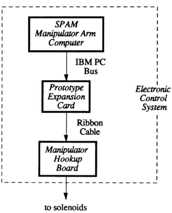
3.4.4. Electronic Control System 68
3.5. 2-link Manipulator Testing & Results 70
3.5.1 Open-Loop Control Testing 71
3.5.2 Closed-Loop Position Control Testing 72
Stewart Platform
75
4.1 The Stewart Platform 75
4.1.1 Geometric Analysis 77
4.1.2 Kinematics 80
4.1.2.1 Inverse Kinematics 81
4.1.2.2 Forward Kinematics 84
4.1.2.3 Kinematic Constraints 86
4.2.1 Joint-Based Control 88
4.2.2 Cartesian-Based Control 90
4.3 Joint Design & Testing 91
4.3.1 PHAD Revisited 91
4.3.2 Universal Joint 94
4.3.3 Spherical Joint 95
4.3.4 JELLO Sensor 98
4.3.5 L-PHAD Servo Control 100
4.4 SPAM Stewart Platform Design 104
4.5 SPAM Stewart Platform Hardware 106
4.5.1 Assembled Hardware 107
4.5.2 Pneumatic System 108
4.5.3 Electronic Control System 109
SPAM Development & Control
112
5.1 Hardware Integration 112
5.2 Distributed Systems 114
5.3 Operation of SPAM 119
5.3.1 User Interface and SPAM Control 119
5.3.2 Operational Issues 119
Conclusion
121
6.1 Current SPAM Hardware 121
6.2 SPAM Development Observations 122
6.3 Recommendations for Future Studies 123
6.3.4 Space Research Topics 126 127
6.4 Research Summary
References
129
Appendix A: SPAM Electronics
131
Appendix B: SPAM Hardware
140
Table of Figures
Figure 1.2.1: SRMS Configuration 15
Figure 2.2.1: A Stewart Platform 21
Figure 2.2.2: Stewart Platform Augmented Manipulator (SPAM) 22
Figure 3.1.1: 2-link planar manipulator 27
Figure 3.1.2: Frame assignments for 2-link planar arm 28
Figure 3.1.3: 3-link anthropomorphic manipulator 30
Figure 3.1.4: Frame assignments for 3-link arm 31
Figure 3.2.1: Open-Loop Position Control 34
Figure 3.2.2: Resolved Motion Rate Control 36
Figure 3.2.3: Closed-loop Position Control 36
Figure 3.2.4: Augmented Closed-Loop Position Control 37
Figure 3.2.5: Closed-loop Tip Controller 37
Figure 3.2.6: Inverse-Jacobian Controller. 38
Figure 3.3.1: Pneumatic and Hydraulic Actuating Device (PHAD) 40
Figure 3.3.2: Diagonally-driven 5-bar linkage 42
Figure 3.3.3: 5-bar linkage motion with diagonal drive 42
Figure 3.3.4 (a): Characteristic curve of 5-bar linkage 43
Figure 3.3.4 (b): Characteristic curve of 5-bar linkage 44
Figure 3.3.4 (c): Characteristic curve of 5-bar linkage 44
Figure 3.3.5: Revolute PHAD-A 46
Figure 3.3.6: Neutrally-buoyant R-PHAD-A 47
Figure 3.3.7: Pivoting 2-bar crank 48
Figure 3.3.8: 2-bar cranking motion 48
Figure 3.3.9 (c): Figure 3.3.10: Figure 3.3.11: Figure 3.3.12: Figure 3.3.13 (a): Figure 3.3.13 (b): Figure 3.3.14: Figure 3.3.15: Figure 3.3.16: Figure 3.3.17 (a): Figure 3.3.17 (b): Figure 3.3.18: Figure 3.3.19 (a): Figure 3.3.19 (b) Figure 3.3.20 (a): Figure 3.3.20 (b): Figure 3.4.1: Figure 3.4.2 (a): Figure 3.4.3: Figure 3.4.4: Figure 3.4.5: Figure 3.4.6: Figure 3.4.7: Figure 3.5.1. Figure 3.5.2: Figure 3.5.2:
Characteristic curve of 2-bar crank R-PHAD-B schematic
R-PHAD-A Optical Encoder Mounting P-D Joint Position Servo
P-D Position Servo (Kp = 1.0, Kd = 0.1) P-D Position Servo (Kp = 2.0, Kd = 0.1)
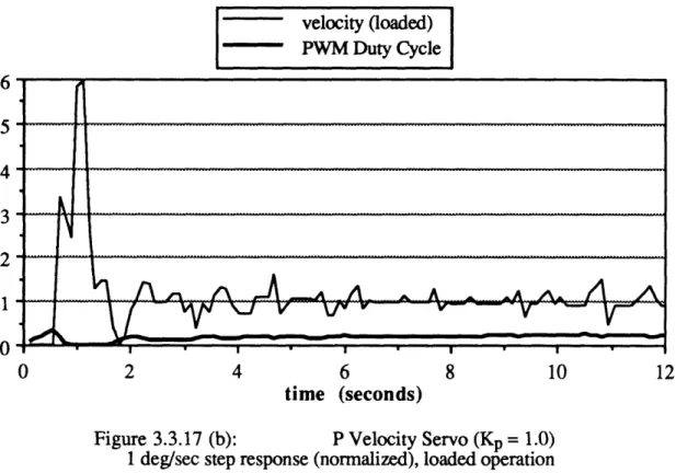
BLAH Controller Logic BLAH Velocity Servo Proportional Velocity Servo P Velocity Servo (Kp = 1.0) P Velocity Servo (Kp = 1.0)
Proportional-plus-derivative Velocity Servo P-D Velocity Servo (Kp = 1.0, Kd = 0.1) P-D Velocity Servo (Kp = 1.0, Kd = 0.1) P-D Velocity Servo (Kp = 1.0, Kd = 0.1) P-D Velocity Servo (Kp = 1.0, Kd = 0.1) Arm Boom Tube Configuration
End plug with Koganei solenoids Joint Collar
Joint/Arm Tube Interface R-PHAD-A Power System
Manipulator Hookup Board (MHB)
SPAM Electronic Control System (schematic) 2-link arm frames (vertical test mounting) SPAM 2-link planar arm
Figure 3.5.3: Figure 3.5.4: Figure 3.5.4: Figure Figure Figure Figure Figure Figure Figure Figure Figure Figure Figure Figure Figure Figure Figure Figure Figure Figure Figure Figure 4.1.1: 4.1.2: 4.1.3: 4.1.4: 4.1.5: 4.2.1: 4.2.2: 4.3.1: 4.3.2: 4.3.3: 4.3.4: 4.3.5: 4.3.6: 4.3.7: 4.3.8: 4.3.9: 4.3.10: 4.3.11: 4.3.12 (a): 4.3.12 (b):
Joint angles resulting from {L2, 0, LO+L1 } command
2-link arm geometry for (L2+0.707L1, 0, L0+0.707L1 command
Joint angles from {L2+0.707L1, 0, L0+0.707L1 } command
Common Stewart Platform Implementation General Stewart Platform
Symmetrical Stewart Platform Geometry Frame and Vector Assignments
Actuator Vector Relationships
Stewart Platform Joint Based Control Stewart Platform Cartesian Based Controller L-PHAD Design Schematic
Assembled L-PHAD Universal Joint Design
Assembled Universal Joint Design Universal Joint Workspace
"Spherical" (U-Joint-plus-Swivel) Design Assembled U-Joint-plus-Swivel Joint Design U-Joint-plus-Swivel Workspace
Joint Encoder with Localized Linear Optics (JELLO) schematic
Joint Encoder with Localized Linear Optics (JELLO) P-D Position Servo P-D Position Servo (Kp = 0.05, Kd = 0.01) P-D Position Servo (Kp = 0.05, Kd = 0.01) 73 73 74 76 77 78 82 83 90 91 92 93 94 95 95 96 97 98 99 99 100 101 101
P-D Position Servo (Kp = 0.05, Kd = 0.01)
Figure 4.4.1: Excel CAD model of Stewart Platform 105
Figure 4.4.2: SPAM Stewart Platform Mounting Points 106
Figure 4.5.1: SPAM Stewart Platform schematic 107
Figure 4.5.2: Assembled SPAM Stewart Platform 108
Figure 4.5.3: SPAM Stewart Platform pneumatic system 109
Figure 4.5.4: NMIS-0001 and NMIS-0021 110
Figure 4.5.5: Stewart Platform Electronics Control System 111
Figure 5.1.1: Adjustable Hinge Coupling 113
Figure 5.2.1: SPAM Distributed Processing Network 118
Figure 6.1.1: SPAM Elbow-to-Stewart Platform (elbow view) 121
Figure 6.1.2: SPAM Elbow-to-Stewart Platform (tip view) 122
Figure 6.3.1: SPAM Stewart Platform Base Frames 126
Chapter 1
Introduction
1.1
SSL Research Background
During the past decade, the MIT Space Systems Laboratory (SSL) has been engaged in the study of orbital productivity. Specifically, this research has been directed towards qualifying and quantifying methods of increasing the productivity of activities in
space. In 1982, the Automation, Robotics, and Machine Intelligence Systems (ARAMIS) study was conducted for NASA to determine the feasibility of introducing man-machine systems and methods to space operations. The results of this study theorized that significant cost savings and increased productivity of specific activities could be achieved by augmenting humans with automation and machine intelligence (Miller et al., 1983).
In the years following ARAMIS, the SSL has focused its efforts in the areas of teleoperation and expert systems. Recent activities have included research into the development of teleoperators for structural assembly, multiple sensor/control loop fusion techniques, autonomous docking and proximity operations, worksite integration of multiple humans and robots, and intelligent control systems. The vast majority of this research has been performed in neutral buoyancy simulations. A neutrally buoyant research environment was selected since it offered the capability to perform full-scale testing of man/machine operations. Furthermore, unlike other environments, neutral buoyancy does not restrict translational or rotational degrees of freedom, and thus offers a high degree of space simulation fidelity.
SSL's neutral buoyancy research has been conducted at two primary research sites, the MIT Alumni Swimming Pool and the NASA / Marshall Space Flight Center Neutral Buoyancy Simulator (MSFC-NBS). The MIT Alumni Swimming Pool, measuring 40 by 75 feet with a maximum depth of 13 feet, offers limited space for large scale activities. Research in this facility has been focused on localized activities such as assembly of structural nodes, proximity operations, and anthropometrics. The MSFC-NBS, on the
payload bay and the Hubble Space Telescope, pressure suits and support facilities, and a Shuttle Remote Manipulator System (SRMS) simulator.
1.2
The SRMS Simulator
The SRMS simulator at the MSFC-NBS is a full scale kinematic simulation of the SRMS. To understand its capabilities and deficiencies, it is first necessary to understand the mechanism it mimics, the Shuttle Remote Manipulator System (SRMS).
1.2.1 Summary of the SRMS
The SRMS was conceived as part of a cooperative development effort between NASA and the National Research Council of Canada. Built by Spar Aerospace (CANADA), the SRMS is intended to provide a controlled means of cargo deployment and retrieval during on-orbit STS missions. It is essentially a six degree-of-freedom manipulator system comprised of a large, three degree-of-freedom anthropomorphic manipulator augmented by a three degree-of-freedom end-effector. The SRMS configuration is shown in diagrammatic form in Figure 1.2.1.
Iii
-rmFigure 1.2.1: SRMS Configuration
(Ussher, T.H., and Doetsch, K. H., An Overview of the Shuttle
Remote Manipulator System, NASA N85-16964, 1985)
NI,
The SRMS delivered to NASA, and currently used on the STS, is 50 ft. in length and weighs 950 lb. It is designed to maneuver a nominal payload of 32,000 lb. and to retrieve a maximum payload weight of 65,000 lb. The operational characteristics of the
SRMS are summarized below in Table 1.1 (Ussher, T. H. 1985). Table 1.1: SRMS Operational Parameters
Degrees-of-freedom 6
Max. tip extension 50 ft (15.24 m)
Min. tip force (straight-arm) 15 lb. (81.96 N) Arm stiffness (straight-arm) 8.4 lb./in. (1,471 N-m) Joint rate hold accuracy + 1 deg./sec.
Tip position hold accuracy ±2 in. (+0.025 m)
Max. tip translation rate 2 ft./sec. (0.61 m/sec)
The SRMS is controllable in any one of four standard, switch-selectable modes. These modes are (1) Manual Augmented, in essence open-loop tip control with translational and rotational hand controller (THC & RHC) Cartesian rate commands resolved into joint rates; (2) Single Joint, which controls an individual joint rate while freezing the other five joints; (3) Direct Drive, whereby fixed rate commands are sent to switch-selected joints; and (4) Automatic Mode, where preprogrammed end-effector position trajectories are used to generate joint rate command sequences. All of these modes except for Direct Drive utilize the General Purpose Computer (GPC) onboard the STS for computation of joint rate commands.
1.2.2 SRMS Simulator Characteristics
The SRMS simulator was intended to provide the MSFC-NBS with the capability of simulating STS tasks involving the SRMS. At the time of the simulator's conception, two hardware simulations of the SRMS had been constructed elsewhere, at the Real-Time Simulation Facility (SIMFAC) in Canada and at NASA's Johnson Space Center (JSC). The SIMFAC simulator was constructed with an air-bearing system to simulate zero gravity. Due to space limitations and logistics, this simulator was useful only for verifying performance of SRMS components. Conversely the JSC simulator, used for training STS crews, was designed to operate in one-g. Although this simulator provided kinematic similarity, its dynamic characteristics were extremely different since it operated in full gravity instead of zero-g. To address the shortcomings of both of these simulators, it was proposed to construct a SRMS simulator at MSFC. Operating a SRMS simulator in the
MSFC-NBS would theoretically be able to offer kinematic similarity as well as provide a high-fidelity simulation of on-orbit conditions.
Although the simulator eventually constructed at the MSFC-NBS is kinematically identical to the SRMS, it differs both from a physical and an operational standpoint. The simulator hardware (e.g. joints, boom structures, etc.) were assembled from surplus equipment at MSFC, waterproofed for operation in the NBS. Additionally, the four SRMS control modes were not implemented in the simulator, the only method being a direct mapping of translational and rotational hand controller offsets to joint rates. Moreover, no effort was made to compensate for the characteristics of a neutrally buoyant environment (e.g. water drag and currents).
As a result of these factors, the SRMS simulator at MSFC-NBS exhibits three prominent differences from the actual SRMS. First, because of the water environment, the system is much less accurate and moves quite sluggishly. This makes precise positioning and deployment/retrieval of payloads significantly harder. Secondly, since the joint actuators were not originally designed for underwater use, the force available in the NBS is much lower. Tests have shown that the maximum tip force that the SRMS simulator can exert is on the order of one pound. This exacerbates the positioning problem because payloads with suboptimal neutral buoyancy cannot be moved. Finally, since the arm cannot be controlled in a closed-loop sense, it is extremely difficult to position the tip at desired positions and orientations. Taken collectively, these shortcomings mean that the SRMS simulator is not a very realistic simulation of the capabilities of the SRMS. Although the SRMS simulator very closely matches the kinematics of the SRMS, in terms of reachable and dexterous workspace, it is severely deficient in its duplication of positioning and performance characteristics.
1.3
Motivation for Research
The current direction of SSL research indicates that future studies will focus to a greater and greater extent on enhancing man/machine system productivity. This may involve investigation of coordinating humans with multiple autonomous and teleoperated robots in performing activities in space. Some potential tasks for study include satellite servicing, structural assembly and maintenance. Additional research may entail quantifying worksite positioning requirements and finding means of reducing the expenditure of consumable supplies. To effect much of this research, however, a positioning system of some form will be required. Since SSL research is conducted primarily in neutral buoyancy, a logical choice to fulfill positioning needs would be a system similiar to the
SRMS simulator at the MSFC-NBS. As discussed in the previous section, however, this simulator has shortcomings which tend to obviate its usefulness.
The problem at hand, therefore, is to develop a neutral buoyancy positioning system that corrects the deficiencies of the MSFC-NBS SRMS simulator. The fundamental requirements for such a system are threefold. First, it should be capable of duplicating the SRMS workspace, in terms of reach and volume. Secondly, it should be designed for robust operation in a neutral buoyancy environment, able to generate large forces in the presence of water drag and currents. Finally, it should be operable by modern control methods and provide an efficient man/machine interface.
In the following chapters an innovative concept, the Stewart Platform Augmented Manipulator (SPAM), is described which fulfills these requirements. The system is in essence a three degree-of-freedom anthropomorphic manipulator arm with revolute joints, augmented with a six degree-of-freedom parallel-link platform micro-manipulator. The SPAM concept, as will be shown, is capable of simulating the SRMS with a high degree of fidelity in neutral buoyancy. Moreover, the system has the potential for higher performance and flexibility than even the actual SRMS can provide.
In Chapter 2 the SPAM concept is presented and a description of the system design specifications is given. Chapter 3 details the development of the anthropomorphic manipulator including the design of an underwater hybrid pneumatic/hydraulic rotary actuator, the implementation and testing of digital rate controllers, and the testing of revolute joints. Chapter 4 describes the design of a parallel-link platform micro-manipulator (often referred to as a Stewart Platform), the development of linear pneumatic/hydraulic actuators, and parallel-link control issues. Chapter 5 presents planned systems integration and operational methods for the complete SPAM system, including a distributed processing system architecture. Finally, Chapter 6 summarizes the findings of this thesis and suggests avenues for future research.
Chapter 2
System Design
2.1
Design Goals
The development of a manipulator-type positioning system for neutral buoyancy was driven by two goals. First, the system had to be kinematically similar to the SRMS. This indicated that the manipulator design should reflect dexterous and reachable workspaces that closely matched those of the SRMS. Secondly, the system had to operate in a robust manner in an underwater environment. This implied that the joint actuators be capable of producing large enough forces to compensate for water drag, and that link rigidity or joint controllability be sufficient to reject disturbing currents.
The design goals for the positioning system were initially based on the SRMS operational characteristics. During the early design phase, however, several modifications to these objectives were made. First, since the primary task is fine positioning, it was specified that the system be capable of fine tip control in six degrees-of-freedom. While the SRMS has a total of six degrees-of-freedom at the tip, the three translational degrees are provided by the large manipulator arm section; making fine translation difficult. Additionally, since the objects intended for positioning are humans and telerobots (which are much less massive than STS payloads), duplication of maximum SRMS tip force was not necessary. Finally, overall arm stiffness was determined not to be a critical design constraint. Although link flexing would have an impact on precise tip positioning, the conclusion was that micro-manipulator actions combined with active control would sufficiently compensate for lack of rigidity.
The easiest means of achieving SRMS react and workspace similarity is simply to duplicate the SRMS hardware arrangement of joints and links. In short, a large, three revolute joint (i.e. shoulder pitch, shoulder yaw, and elbow pitch) anthropomorphic arm augmented with a three revolute joint (wrist roll, pitch, and yaw) end-effector should be constructed. In this arrangement, the large arm provides large reach capability while the end-effector provides fine tip angular position control. This system is readily accomplished in neutral buoyancy, as demonstrated by the MSFC-NBS manipulator. Unfortunately
though, this approach has a significant drawback since it utilizes a serial-link end-effector at the large arm's tip.
Serial-link mechanisms, though able to provide high positioning accuracy and positioning ease, typically are incapable of producing large forces. Generally speaking, this is not a problem since other devices or mechanisms can fulfill requirements for force. In an underwater environment, however, force production capability is a matter of concern since large water forces, such as drag and currents, are present.
In the case of the MSFC-NBS SRMS simulator, the serial-link end-effector attached to the large arm does not generate a large amount of force. Consequently, the large arm is relied upon to produce tip forces when positioning objects. Since this requires extremely minute joint control, which is difficult to achieve with long linkages, fine positioning is extremely hard to perform. In essence, any positioning advantages offered by the end-effector are totally offset by the inability to produce strong forces. As the MSFC-NBS simulator demonstrates, a serial-link end-effector is not a viable solution for fine positioning in neutral buoyancy.
2.2
The Stewart Platform Augmented Manipulator
2.2.1 SPAM Concept Development
An elegant solution to the tip positioning problem is to replace the 3 jointed, serial-link wrist with a parallel-serial-link mechanism. Parallel-serial-link, or closed kinematic chain, devices are alternatives to traditional serial type mechanisms in which two or more linkages connect the base of the manipulator with the end-effector. The direct benefits of this arrangement are (Ismail, A., 1984):
* High strength and stiffness-to-weight ratios can be achieved since the links do not carry moment loads but act only in tension and compression. * Positioning of the end-effector is performed by actuators acting in parallel,
resulting in a total force and moment capability greater than each individual servomechanism.
* Moving only the end-effector in space rather than massive servomechanisms results in economy of power, excellent dynamic performance, and low manipulator inertia.
Since all of these characteristics are advantageous for underwater mechanisms, it seems natural to implement a parallel-link mechanism in neutral buoyancy.
The design task, therefore, is to create a positioning system that combines a large manipulator arm with a six degree-of-freedom parallel-link micromanipulator. One concept that matches this description is the Stewart Platform Augmented Manipulator (SPAM). In this system, a three degree-of-freedom, anthropomorphic manipulator arm is augmented by a parallel-link mechanism called a Stewart Platform.
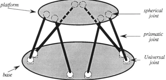
The Stewart Platform is a space truss comprised of six prismatic actuators, each mounted by a universal joint to the manipulator base and by a spherical joint to the top platform. Figure 2.2.1 depicts a typical Stewart Platform. This arrangement of actuators allows the platform to be placed in any position and orientation (i.e. with six degrees-of-freedom) within a certain volume of space.
platform base spherical joint prismatic joint Universal joint
Figure 2.2.1: A Stewart Platform
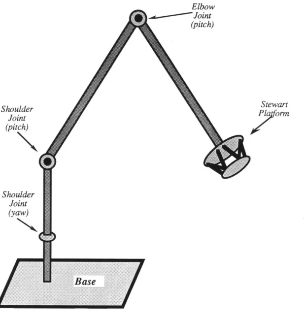
In the SPAM concept, the large, anthropomorphic manipulator arm provides coarse positioning and large reach capability with three revolute joints. The Stewart Platform, which augments the manipulator, offers fine tip positioning in six degrees-of-freedom. Moreover, it has the characteristics (e.g. strength, stiffness, power, etc.) of parallel-link devices which are advantageous for underwater operation. The complete SPAM system is illustrated schematically in Figure 2.2.2.
21
Elbow
Figure 2.2.2: Stewart Platform Augmented Manipulator (SPAM)
(schematic)
Detailed design specifications for the two main components of SPAM, the manipulator arm and the Stewart Platform, are presented in the following two sections.
2.2.2 3-DOF Manipulator Design Specifications
The preliminary design specifications for the large arm component of SPAM were derived from the SRMS. Three revolute joints arranged anthropomorphically (i.e. shoulder yaw, shoulder pitch, and elbow pitch) are connected by straight link sections. As with the
Shoulder Joint (pitch) Shoulder Joint (yaw) Stewart
Porrn
SRMS kinematic simulation, therefore, simply requires a duplication of SRMS linkage lengths.
If the joints and linkages are modularly designed, however, mechanisms other than the SRMS may be simulated. As a result, linkage lengths were not specified as a fundamental design specification, but modularity was included in the baseline. Tip accuracy was assumed to be within one percent of the maximum manipulator translational reach. The SRMS 15 lb. straight arm tip force (corresponding to a total linkage length of 50 ft.) resulted in a maximum shoulder joint torque specification of 750 ft-lb.
A summary of the baseline design specifications for the manipulator is presented in Table 2.1.
Table 2.1: Manipulator Baseline Specifications
Degrees-of-freedom 3
Number of joints & type 3 revolute
Joint range of motion 180 degrees
Joint torque capability 750 ft-lb. (1,017 N-m)
Joint rate hold accuracy +1 deg./sec.
Tip position accuracy >1 % max reach
Tip position hold accuracy ±2 in. (±0.051 m)
Max. tip translation rate 2 ft./sec. (0.61 m/sec)
2.2.3 6-DOF Stewart Platform Specifications
The design specifications for the Stewart Platform component of SPAM were based on SRMS tip characteristics with consideration given for operation in an underwater environment. To match SRMS tip positioning, the Stewart Platform must have, at a minimum, ±1 inch translational position accuracy. The translational workspace requirements were derived from the assumption that the large arm can position the end-effector to within one percent of the maximum translational reach. For a 50 ft arm, this indicates that the Stewart Platform should be capable of ±6 inches movement in three translational axes.
The SRMS wrist provides only three degrees-of-freedom in the end-effector workspace. Since the Stewart Platform provides a total of six degrees-of-freedom, SPAM has three more degrees of tip freedom than the SRMS. To offer a large and flexible end-effector workspace for positioning, it was decided that ±45 degrees of rotational movement in 3 axes would prove to be sufficient. To overcome water forces and to provide 15 lbs of end-effector force (equivalent to SRMS minimum tip force), each actuator had to be capable of generating at least 15 lbs of force.
A summary of the baseline design specifications for the Stewart Platform is presented below in Table 2.2.
Table 2.2: Stewart Platform Baseline Specifications
Degrees-of-freedom 6
Number of joints & type 6 prismatic
Joint force capability 15 lbs. (66.7 N)
Translational accuracy ±1 inch (-0.025 m)
Translational range ±6 inches (-0.15 m)
Chapter 3
Manipulator Arm
The task of constructing the manipulator arm component of SPAM was separated into several design and testing phases. In the first phase, a revolute joint was developed for underwater operation. This entailed actuator research and development, linkage design, fabrication, instrumentation, control systems design, and testing. For the second phase, a 2-link manipulator was assembled and operated in neutral-buoyancy. Control systems were implemented via computer and tests conducted to determine viability of various control schemes. The third and final phase involved the construction and operational testing of the full 3-link manipulator. At the present time, however, this phase has not been completed.
3.1
Manipulator Kinematics
In this section, the kinematics for 2-link and 3-link serial-link manipulators are presented. A serial-link manipulator is essentially a series of rigid bodies connected in a chain structure. Such an arrangement is often referred to as an open kinematic chain (Asada, 1986). Two mappings completely characterize serial-link manipulator geometry. The forward kinematics mapping relates the natural coordinates of a manipulator to reference coordinates. Similarly, the inverse kinematics mapping transforms reference coordinates to natural coordinates. These two mappings are often used with respect to the end-effector. Given a description of natural coordinates (e.g. joint angles), for example, the forward kinematics are used to compute the end-effector position and orientation in some reference frame (e.g. Cartesian coordinates). Conversely, given position and orientation in a reference frame, the inverse kinematics are used to calculate the set of joint angles which will place the end-effector in the specified location.
The natural coordinates for a serial-link manipulator having n degrees-of-freedom is a set of n joint variables (Craig, 1986). If the manipulator is comprised only of revolute joints, for example, the set of joint variables is the set of all the joint angles. This may be expressed as a vector in joint space:
01 01
0= . (3.1)
The reference coordinates most frequently used are Cartesian coordinates, with an orthonormal frame to describe position and Euler angle rotations to describe orientation. This may be expressed as a 6x1 vector in Cartesian space (using Roll-Pitch-Yaw Euler angles): x y z 9 -I, (3.2)
where , 0, 0, are right-handed rotations about the x, y, z axes respectively. The forward kinematics mapping, F, is then:
F:8 0 X (3.3)
Similarly, the inverse kinematics mapping, G, is:
G : X =- 0 (3.4)
For serial-link manipulators, frames are assigned to the manipulator base, to each joint in the chain, and to the end-effector (tip). The mapping of positions from frame A to
frame B is then performed with a 4x4 homogeneous transform matrix, BT:
Ap -_A Bp ]
(3.5)
BR APB ORG 000 1where: Ap is a 3x1 Cartesian position vector in frame (A)
Bpis a 3x1 Cartesian position vector in frame ( B) ApB ORG is the location of the origin of (B) in
{
A)
R
The forward kinematics of the manipulator is, therefore, the transformation from the manipulator base frame 0) to the end-effector frame (T), T.
Determining manipulator inverse kinematics is problematic since the kinematic equations are highly non-linear and a general closed-form solution does not exist. However, several approaches to solving the inverse kinematics problem are described in the literature for serial-link manipulators (i.e. algebraic manipulation, geometric decomposition, Pieper's method, etc.) which may result in the desired closed-form solution. It should be noted that a universal, numerical solution does exist for 6 degree-of-freedom, serial-link manipulators composed of revolute and prismatic joints (Craig, 1986). From an inverse kinematics applications perspective, however, a numerical method is considered to be suboptimal since it necessitates a significantly greater amount of iterative computation than a closed-form method, and because such a technique is not guaranteed to discover all the solutions of the problem.
3.1.1. 2-Link Manipulator
The 2-link manipulator was designed to have two revolute joints, shoulder pitch and elbow pitch. Since the two joint axes are parallel, the manipulator is an extremely simple planar arm as shown in Figure 3.1.1.
/
shoulder
Figure 3.1.1: 2-link planar manipulator
The frames assigned to the manipulator joints follow the convention in (Craig, 1986). The reference frame (0) is affixed to the base. Frame (1) is attached to the first
joint (shoulder) and aligns with (0) when the shoulder angle is zero. Frame (2) is attached to the second joint (elbow) and aligns with ({ 1) when the elbow angle is zero. Frame (T}, the tip frame, is located at the end of the elbow link. The 2-link arm with frame assignments is shown in Figure 3.1.2
A A XT /T A Y Y2 V-777
Figure 3.1.2: Frame assignments for 2-link planar arm
3.1.1.1. Forward Kinematics
The frame transformations for the 2-link Cl Sl 0 0 c2 S2 0 0 1 0 01 00 00
planar arm are:
-Si Cl 0 0 -S2 C2 0 0
0 L2
00
10
0 1 (3.6)----
---Multiplying these matrices together, produces the desired forward kinematics transform: S12 -s12 0 Llc1+L2C12 O s12 -'12 0 0 0 1 L1sl+L0 2s12 (3.7a)
0 0 0
0
where cl2 = cos(91 + 02).The kinematic equations relating the joint angles to the tip location, referenced to frame (0), are found in column 4 of the above:
x = LlcX + L2c12 (3.7b)
y = Lls, + L2s12
3.1.1.2. Inverse Kinematics
Following the algebraic solution method presented in (Craig, 1986) results in the desired inverse kinematics. The equations relating the tip position, referenced to frame ({ 0), to the joint angles are:
01 = Atan2(y, x) - Atan2(K2,K1) (3.8) 92 = Atan2(s2, c2) where: x2 + y2 _ L2 2 c2 = (3.9) 2L1L2
s2 = ±_1-(c2)
2(3.10)
K1 = Li+L2C2 (3.11) K2 = L2s2There are several items to note in the preceding. First, the two argument arc tangent function is used in (3.8) to determine the quadrant containing the resulting angle. Secondly, for a solution to exist, the the right-hand side of (3.9) must be in the range [-1, 1]. If this constraint is not met, then the specified tip position is outside the reachable workspace. Finally, the multiple solutions of (3.10) correspond to multiple geometric configurations of the arm that result in the same tip position.
3.1.2. 3-Link Manipulator
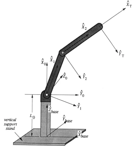
The 3-link manipulator was designed to have three revolute joints in an anthropomorphic configuration; shoulder yaw, shoulder pitch and elbow pitch. The
~
shoulder yaw joint axis, located at the manipulator base, is normal to the shoulder joint pitch axis. Since the shoulder pitch joint and elbow joint axes are parallel, the shoulder pitch/elbow section is identical to the 2-link manipulator. The 3-link manipulator is shown in Figure 3.1.3. 62
shoulder
pitch shoulder L1 yaw ~ii~Nii~Figure 3.1.3: 3-link anthropomorphic manipulator
The reference frame, frame (0), is affixed to the base. Frame (1) is attached to the shoulder yaw joint and aligns with the reference frame when the joint angle is zero. Frame { 2) is attached to the shoulder pitch joint. Frame { 3 , attached to the elbow joint, aligns with frame (2) when the elbow angle is zero. The tip frame, frame (4) is located at the end of the elbow link. The frame assignments for the 3-link manipulator are shown in Figure
A YT A
X
3 A '3 Y2 Zo Z1 ^. z//
I/1
A Y A X1FFrame assignments for 3-link arm
XA
XT
i
3.1.2.1. Forward Kinematics
The frame transformations for the 3-link anthropomorphic arm are:
-Sl Cl 0 0 C2 0 -S2 0 -S3 C3 0 0
OT
2'T
2
T
T=
Multiplying these matrices together, produces the desired forward kinematics:
C1S23
OT = SIS23 T C23LcO
CIC23 $1S23 -S23 0 -S1 Cl1 0 0 L2C1S2 + L3Cs1 23 L2S1S2 + L3S1S23 L1 + L2C2 + L3C23 1The kinematic equations relating the joint angles to the tip location, referenced to frame {0}, are contained in column 4 of (3.13a):
x = L2CIS2 + L3C1S2 3
y = L2SIS2 + L3S1S2 3 z = L1+ L2C2 + L3C2 3
(3.13b)
3.1.2.2. Inverse Kinematics
Since the 3-link anthropomorphic manipulator is essentially the 2-link planar arm augmented with a revolute base joint, the inverse kinematic mapping is easy to obtain. First, use the specified x, y tip position (in frame
{
0)) with the two argument arc-tangent tocalculate the shoulder yaw angle. Next, rewrite the specified Cartesian tip position in cylindrical coordinates, accounting for the base to shoulder pitch joint separation distance. (3.12) (3.13a) L3 0 0 1
Finally, apply the 2-link arm solution using the cylindrical coordinates. The complete inverse kinematic solution is given below:
01 = Atan2(x, y) (3.14) R = x2 +
y
2 (3.15) Hz-L 1 (3.15) H= z-L1 62 = Atan2(R, H) - Atan2(K2,K1) (3.16) 93 = Atan2(s3, c3) where: R2 + H2- L2 - L32 c3 = (3.17) 2L2L3 s3 = 1 - (cos 632 (3.18) K1 = L2+L3C3 (3.19) K2 = L3s3Equations (3.14) to (3.19), of course, are subject to the same constraints on the 2-link solution given in section 3.1.1.2. As a result, only the shoulder yaw angle has a unique solution.
3.2.
Manipulator Control Schemes
The control problem for serial-link manipulators is an inherently nonlinear one. Since a serial-link manipulator is a chain of rigid bodies, mass and inertia parameters are dependent on the manipulator configuration and are therefore time varying. Additionally, actuator non-linearities such as friction contribute to the difficulty of accurately modeling a manipulator system. Model based controllers, therefore, must compensate for changing manipulator characteristics by providing some form of adaptive or non-linear control. System linearization may be used to derive locally linear models if nonlinearities are not a significant factor about an operating point. This approach has limited usefulness, however, since it requires a changing linearized model as the manipulator moves from point to point.
For a manipulator operating in neutral buoyancy, modeling of the system is further complicated. Water forces (e.g. drag, damping and turbulence) are highly non-linear and strongly dependent on the velocity of moving components. As a result, it is even more difficult to derive a system model upon which to base a controller. Non-linear methods
such as sliding-surface offer the potential to alleviate this problem since such techniques are able to produce extremely robust controllers.
The following sections describe several methods for controlling serial-link manipulators. Specifically, techniques for position and velocity control of the end-effector are detailed. Sections 3.2.1 to 3.2.4 present joint-based controllers, in which controller errors are represented in joint-space. Such controllers are fairly easy to implement and are found on a vast number of current commercial systems. The final section (3.2.5) describes
a Cartesian-based controller which maps controller errors in Cartesian space rather than
joint space.
It should be noted that in all of these methods the manipulator is controlled with simple, error-driven controllers. Furthermore, each joint of the manipulator is operated independently without regard to the other joints by a localized servo controller. A serious deficiency of this methodology is that no attempt is made to derive and utilize a system model. At first glance, such an approach would appear to be a poor choice since it is impossible to guarantee optimal, or even fair, performance of the arm in all configurations. However, since derivation of a model structure is problematic and because determination of model parameters (e.g. inertia moments, center of mass, etc.) is difficult, the benefits offered by model-based control may be few. Moreover, such controllers are likely to be computationally intensive, requiring fairly powerful computer power. On the other hand, the individual joint approach based on simple control laws requires few calculations so that low computational power will suffice.
3.2.1. Open-Loop Position
In this control scheme, the manipulator tip is controlled open-loop since there is no direct feedback of tip position. As a result, this method has limited appeal for direct tip positioning control. During operation of the manipulator, joint position commands are fed directly on a joint-by-joint basis to position servocontrollers, which receive joint position feedback. This is illustrated by block diagram in Figure 3.2.1. The resulting tip location may be determined by applying manipulator forward kinematics to the joint positions.
For a human operator, this control scheme is feasible if the proper user interface is chosen. With an anthropometric manipulator, for example, one possible approach is to utilize similarity between a scaled model and the controlled arm. By controlling the tip of the scaled, master arm, inverse kinematics are implicitly performed and provide joint position commands for the slave manipulator. This technique has been used extensively for teleoperation tasks in the nuclear industry as well as for structural assembly research in the SSL.
Moreover, it is possible to "teach" a manipulator how to perform a specific task. This is accomplished by first having a human operator guiding (i.e. operating) the manipulator through a desired set of motions and sequentially storing sets of joint positions. Later, a sequencer plays back the series of joint sets, effectively commanding the manipulator to duplicate human actions. The primary application of teaching by showing is for programming a manipulator to perform repetitive tasks, reducing human operator workload.
3.2.2. Open-Loop Resolved Motion Rate
A more useful tip control scheme than open-loop position is referred to as resolved
rate or resolved motion rate control and is attributed to D.E. Whitney. In resolved rate
control, given desired manipulator tip velocities, joint rates are determined which will cause the manipulator tip to move at the desired velocities. One common approach is to utilize the inverse Jacobian mapping to resolve Cartesian velocities into joint rates:
Od = (0)-1 0Xd (3.20)
where the leading, superscripted zero indicates terms written with respect to the base frame. However, since the Jacobian is dependent on manipulator configuration, it is possible for it to become singular. In this case, the inverse Jacobian does not exist, and a determination of joint rates via (3.20) is not possible. Furthermore, as the manipulator approaches a singular configuration, the denominator of (3.20) tends towards zero and may result in excessively large joint velocities.
During resolved rate control the operator, in essence, "flies" the tip of the manipulator. Cartesian tip velocity commands are passed through a rate resolver to joint rate servos. The controller is shown schematically in Figure 3.2.2. Since there is no explicit feedback of tip position, tip control is technically in an open-loop sense. However, resolved motion rate control allows the operator to directly control the tip velocity in a
Cartesian sense. This is a significant advantage over open-loop position control since manipulator operation is more intuitive and places fewer demands on a human operator.
Figure 3.2.2: Resolved Motion Rate Control
An alternative to Jacobian-based resolved rate control is joint space differencing. In this technique, given a planned path of desired Cartesian tip states, X = f(t), joint positions are found by applying manipulator inverse kinematics. Joint rates are then determined by differencing of joint positions and are passed to the joint rate servos. This approach is perhaps easier to implement since fewer calculations are required than computing the inverse Jacobian. Differencing effects, however, warrant careful consideration (i.e. causality, sampling rate, noise, etc.) It should be noted that multiple solutions and singularities generated by inverse kinematics are also problems.
3.2.3. Closed-Loop Position
The simplest closed-loop scheme focuses on feedback of tip position. Desired Cartesian manipulator location, typically tip position with respect to the base frame, are converted to joint positions via inverse-kinematics. These positions are then directed to joint position servos. Since the servos operate on joint position, control errors are reflected in joint-space. This system operates in a closed-loop sense since tip position, transformed into joint positions by inverse-kinematics, is reflected in the joint-space controller error. Figure 3.2.3 shows a block diagram of closed-loop position control.
ma
Xd
Operator
4
Figure 3.2.3: Closed-loop Position Control
In practice, this control scheme is generally augmented with a path planning module (either Cartesian or joint-space) which generates trajectories between specified endpoints or
singularity handling, smoothness of trajectory (i.e. continuous first and second derivatives), and obstacle avoidance. The addition of a trajectory generator, however, dramatically increases computation demands on the manipulator controller and is not always feasible for real-time operations. The augmented closed-loop controller is shown below in Figure 3.2.4.
Figure 3.2.4: Augmented Closed-Loop Position Control
3.2.4. Closed-Loop Tip Control
Although the closed-loop controller described in the previous section has some usefulness, it cannot be used to explicitly control tip velocity. The only means of specifying velocities to this controller is through the augmented path planner (i.e. velocity transformed into trajectory positions). This approach is suboptimal, however, since the path planner must produce joint position commands closely spaced in time to achieve any degree of velocity precision. Moreover, there is no direct tracking of velocity error since the controller operates solely on joint position.
The preferred means of tip position and velocity control is to implement a multiple-input, multiple-output (MIMO) controller. In this scheme, desired cartesian position and velocities are resolved into joint angles and rates which are transformed into joint commands via some type of state-space control law structure. Transformation of position to joint angle is usually performed with inverse kinematics, while resolution of velocity to joint rate is accomplished by the inverse Jacobian. Since the controller is based in state-space, there is a vast assortment of possible control structure (e.g. pole-placement, LQR/LQG, etc.). Depending on the choice of control law, the low-level joint controller may be either a position or a velocity servo, though the latter is more common. A block diagram of this controller is shown in Figure 3.2.5.
Figure 3.2.5: Closed-loop Tip Controller
As the figure shows, tip position and velocity errors are reflected in joint-space, with the MIMO controller inside the feedback loop.
3.2.5. Inverse Jacobian Controller
The tip control schemes described in previous sections (3.2.2 to 3.2.4) operate on errors described in joint-space. Since operator commands are generally given in Cartesian space, all of these methods require conversion to compute joint-space parameters. The primary difficulty with this approach is that the conversion process is computationally expensive (e.g. inversion of the Jacobian and its derivatives), particularly if higher order path derivatives are specified. In practice, typical current systems only transform position commands to joint angles. Velocity, and any other higher derivative, is then computed using differencing techniques. Differencing, however, may introduce undesirable side-effects such as lag and noise amplification. (Craig, 1986). Since commanding higher order derivatives (e.g. acceleration, jerk, etc.) is desirable, the problem is to suggest an alternative to joint-based control which requires fewer computations to obtain the required derivatives.
One approach to manipulator control which offers a potential solution is described in (Craig, 1986) as the Inverse Jacobian controller. In this scheme, controller errors are mapped to Cartesian space by introducing coordinate transformations directly into the servo loop. Cartesian errors (presumed to be small) may be mapped to joint-space displacements using the inverse Jacobian. These displacements are then converted to actuator commands which reduce the Cartesian errors. The structure of this control scheme is shown in Figure
3.2.6.
3.3.
Revolute Joint Design & Testing
In order to realize the serial-link manipulators described in section 3.1 in a neutral buoyancy environment, it was necessary to create a revolute joint for underwater operation. To implement the controllers detailed in section 3.2, it was additionally necessary to devise joint position and rate servocontrollers. Details of the development process and final design
for both are given in the following.
3.3.1. Development of Neutral Buoyancy Actuators
The underwater setting associated with neutral buoyancy simulation is an extremely challenging environment for actuator design. Among the difficulties that must be considered in the design of such devices are corrosion, lubrication, and the electrical conductivity of water. The situation is further complicated when humans are introduced to the scene since consideration must be made for confinement of contaminants and safety factors. Moreover, since the baseline specifications for SPAM called for a high-torque revolute joint and a high-force linear actuator, it was mandated that any actuator design be capable of high power output. Taken collectively, these factors meant that the development of actuators for SPAM was not a trivial task.
Three fundamental criteria were selected to drive the actuator design. First, to minimize the deleterious effects of water, moving components and linkages were desired to be as mechanically simple as possible. Secondly, the means used to power the actuator had to be safe to submerged humans. Finally, the actuator was specified to be as cost-effective as possible.
To fulfill these requirements, a substantial research effort was made to determine the viability of various actuation schemes. Among the methods rejected after evaluation were electrical torque motors with gearing, pneumatically driven motors, and hydraulics. The first approach, electrical torque motor with gearing, was abandoned because of potential high voltage/currents and due to the gear lubrication problems. Pneumatically driven motors, though offering high torque at a low cost, had to be rejected since the required lubricated air supply presented a potential contaminant problem. Finally, hydraulics involving oil was dismissed since absolute prevention of oil leakage and spillage is extremely troublesome.
After rejecting traditional actuation methods, research was focused on novel approaches to actuator design. One such approach is the "water over air" cylinder. In this scheme, compressed air is used to supply actuating force and water, assumed to be incompressible, is used for braking and control. Since compressed air is clean, and because
water is readily available in neutral buoyancy, it was decided to pursue development of a high-powered actuator using this concept.
The Pneumatic and Hydraulic Actuating Device (PHAD) is the result of these efforts. The PHAD, shown schematically in Figure 3.3.1, is a parallel arrangement of three cylinders, two pneumatic and one hydraulic. Air and water flow control is provided by solenoid valves. The air cylinders and solenoid valves are sized to meet force and supply demands. The hydraulic cylinder and solenoids are chosen according to braking and control considerations. Three cylinders were used in the PHAD design to guarantee balanced applied and braking forces.
Cylinder Mount Piston Block Block Water
...
.
Solenoid Valve . ... ....a
e
...
Air ... .O e....Solenoid
I::I:SB ~ :~ ·... :::::::'...-:
A
ir
'i"#;i~iiiii~iii
....
...
...
/
Valve
/
Piston RodFigure 3.3.1: Pneumatic and Hydraulic Actuating Device (PHAD)
(schematic)
During PHAD operation, compressed air is supplied to one side of the pneumatic cylinders. Since the hydraulic cylinder is sealed and contains an incompressible fluid (i.e. water), the PHAD pistons remain in a static position. Opening the water solenoid valves allows water flow, and hence, the pistons move. Moreover, if the period the water solenoids are open is regulated by some method (e.g. pulse-width modulation), precise linear actuation is possible. To illustrate this, consider the PHAD depicted in Figure 3.3.1. Suppling air to the left side of the air cylinders drives the pistons to the right, extending the piston rods. Controlling the water solenoids, and hence water flow through the hydraulic cylinder, regulates the piston rod extension speed. It should be noted that because the water
solenoids are used as ON/OFF switches, and do not actually regulate flow volume, the PHAD is essentially a linear stepper.
For all of the PHAD implementations, compressed air is supplied to the pneumatic cylinders from a first-stage scuba regulator mounted on a 72 cu. ft. air tank. The regulator used, Scubapro model MK100, delivers 125-140 p.s.i. high-pressure air depending on ambient pressure and flow rate demand. Air flow control is provided by Koganei 110-4E1-F11 solenoid valves equipped with a 12 VDC coil. The supply of water is obtained directly from the surrounding environment. Laketown or KIP solenoids are used to control the intake and output flow of water from the hydraulic cylinders. The choice of Laketown or KIP solenoids is implementation specific and is dependent on hydraulic braking force considerations.
Three implementations of the PHAD concept were constructed. First, a revolute variant was developed to provide the in-line pitching required by the serial-link manipulator shoulder and elbow pitch joints. Since the PHAD is a linear device, it was necessary to employ a 5-bar linkage to convert motion from translation to rotation. This variant is
described in section 3.3.2. Secondly, a different revolute variant was designed to provide
the rotation required by the manipulator base-mounted shoulder yaw joint. For this variation, described in section 3.3.3, a 2-bar pivot was used. Finally, a linear PHAD was constructed for actuation of the Stewart Platform. This implementation is discussed in detail in section 4.3.1.
3.3.2. Revolute PHAD-A
To provide the pitching motion required by the SPAM manipulator shoulder pitch and elbow joints it is necessary to convert PHAD linear motion to rotation. Of the many
potential means of performing this conversion, gearing and closed-chain linkages were
studied. Gearing, using a toothed rack and gear system, is highly desirable since it produces constant rotation for constant linear motion and constant torque for constant linear force. Unfortunately, several problems (e.g. underwater lubrication, required gearing ratio, mounting location) made implementation unfeasible. Closed-chain linkages, on the other hand, are extremely simple mechanical devices and do not have these intrinsic difficulties. The disadvantage is that all closed-chain linkages have a non-linear relationship between linear and rotational motion. The logistical simplicity for implementation, however, resulted in a decision to utilize a closed-chain linkage with the PHAD, regardless of non-linearities.
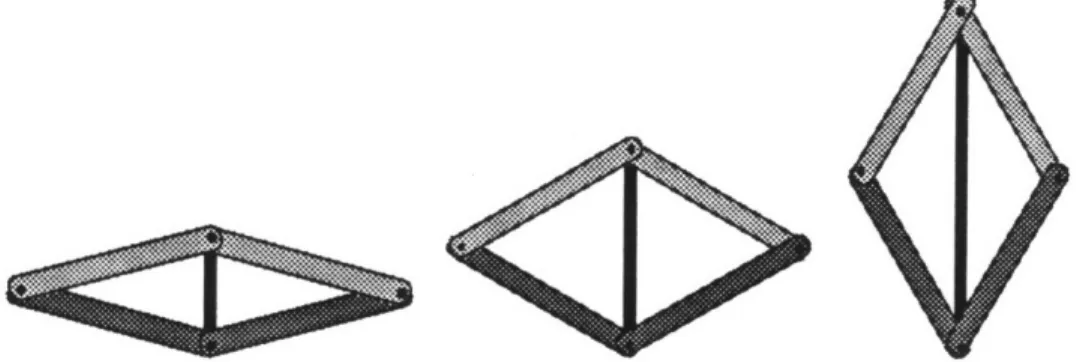
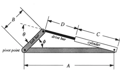
As a result, a diagonally-driven 5-bar linkage was used to convert PHAD linear motion to rotation. The 5-bar linkage was chosen since it is has few links, provides good
torque to force ratios, and is a compact spatial arrangement. As shown in Figure 3.3.2, the linkage is symmetrical with two upper link members and two lower link members joined by the diagonal drive.
UPper pivot
ower pivot
Figure 3.3.2: Diagonally-driven 5-bar linkage
In this configuration, extension of the center (drive) bar diagonally drives the linkage, causing the link bars to rotate about four pivot points. The motion is illustrated below in Figure 3.3.3
Figure 3.3.3: 5-bar linkage motion with diagonal drive
left to right - increasing drive bar extension