ABSTRACT 1
In conventional internal combustion engines, gas flow in and
out of the cylinders is controlled by poppet valves actuated by
a disc cam (usually through some linkage). A spring is used which
compresses as the valve lifts off its seat. This spring provides
the force which overcomes the inertia of the valve train during
that part of the cycle when the acceleration reverses direction
and the inertia forces tend to make the valve train lose contact
with the cam surface. This spring provides the force which
over-comes the inertia of the valve train during that part of the cycle
when the acceleration reverses direction and the inertia forces
tend to make the valve train lose contact with the cam surface.
This spring, then, controls the valve motion during the part of
the lift cycle whentthe valve is decelerating. However, vibrational
problems are inherent in systems containing springs, and resonating
and surging of the spring can be a major problem with this type
of design, sometimes leading to the breakage of the spring and
failure of the system.
In contrast to a valve system which is partially spring
con-trolled, a completely desmodromic valve mechanism may be defined
as a system which provides valve actuation which is not
spring-controlled during any part of the lift cycle. A fully desmodromic
system does not contain any springs. The term "desmodromicl is
usually associated with poppet valves, but if it is enlarged to
include any type of valves, then a sleeve valve engine has
desmo-dromic valve actuation.
A semi-desmodromic valve mechanism may be defined as one
which contains a precompressed spring which is not further
compress-ed as the valve lifts off.iits seat. This spring is merely used
to overcome "the inertia" Qf the valve k&rswhen the acaeleration
changes sign. Since the spting does not experience cyclical
com-pression and expansion, vibrational problems are not a factor. The spring functions at constant lengU] Iless the engine speed is raised above that which was used to calculate the spring preload
necessary to overcome the inertia forces.
A valve actuation system can also be designed which combines
the best features of full dedmodromic and conventional systems.
This type of system has many advantages under certain conditions.
This might be called a three-quarter desmodromic system.
The valve actuation system designed is meant to be run as a
three-quarter desmodromic system, although it can easily be converted
to a semi-desmodromic system. It is designed for a standard C F R
eggtna, using as many standard parts as could be retained.
The design outlinedhere is for the standard C F R test engine.
The standard crankcase camshaft mounting id retained and the valves
are actuated by means of pushrods and levers. An engine speed of
5000R RPM was used for calculation of accelerations and stresses.
Initially, it was hoped that the design could be completed
in time to build and test the system, but this proved impossible
to accomplish Within the alloted time. Therefore, the project was
condidered as a design thesis only, with the hope that it might be built and tested as a separate thesis at some future date.
Thesis Supervisor:- ---
7---Prof. A. R. Rogowski
INDEX SUBJECT 1. Title Page 2. Abstract 3. Index 4. Acknowledgements 5. Introduction 6. Design Considerations
7. Comparitive Loads on the Camshaft for
Desmodromic and Convential Systems
Design Conclusions General Conclusions Figures 1 through 11 Sample Calculations Figures 31 and S2 Appendix Figures Al through A7 Design Blueprints PAGES 1-2
3
4
5-7
8-1617-19
8.9.
10. 11. 12. 13. 14. 15. 20 21 22-32 33-42 43-44 Al -A4I wish to thank Professor A. R. Rogowski of Sloan Laboratory for his advice on theoretical and practical aspects of the design.
Mr J. Collagero's intimate knowledge of the C F R engine and
available special components proved invaluable. I also wish to thank Mr. R. J. Raymond and Mr. P. Wassmouth for their advice and assistance.
'5
INTRODUCTION
In conventional practice, the valve actuation of an internal
combustion &ngine is accomplished by means of a disk cam which
con-trols the valve motion through various linkages (except in some
engines where the cam actuates the valve directly). The
recip-rocating parts are held in contadt with the cam by means of a spring
which is compressed as the valve is lifted off its seat. The valve
gear must be decelerated during the period of maximum lift when the
acceleration changes sign. During this part of the lift cycle, the
spring must be relied upon to provide enough force to balance the
inertia force due to the valve gear, so as to keep the linkage in
contact with the gear at all times. Therefore, during this part
of the lift cycle, the valve motion is spring controlled.
Because the spring is subjected to cyclical compression,
vibrational problems often aride. The spring, for instance, may
be subjected to a forcing frequency equal to the natural frequency
of the spring mass system. In this case, the spring often fails
to perform its function and the valve gear loses contact with the
cam surface. Usually, the natural frequency of the system is far
above the maximum driving frequency, but the driving motion is an
irregular one, and, as such, must be represented by a Fourier
series. If one of the lower harmonics of the driving frequency is
equal to the natural frequency, then trouble will result. The
kafmov CS
higher frequencyg are small in amplitude and generally are not
significant.
The spring may also fail because of surging. Surging is
essentially caused by the compression wave which runs up and down
the spring when it is subjected to a sudden displacement. This
wave is caused by the inertia lag of the center of the spring.
In extreme cases it can cause the spring to become overstressed a and break.
Valve springs also have another limitation. The maximum force
which can be exerted by the valve spring is fixed by the spring rate
and the maximum total compression. Valve accelerations, however,
6
rise as the square of the engine speed. Therefore, if the engine
is run above the speed where the spring force is just sufficient
to balance the total inertia force, the valve will tend to lift
be-yond the maximum lift provided bqr the camand smash against the cam
surface on the way down, causing shock loads and scuffing. If the
is run still faster, the valves may not close at all, but merely
oscillate in an open position. Since the burning gases can blow
out through both intake and exhaust ports under this condition, the
valves may be melted or a fire may start in the intake manifold, or the valves may bounce against the piston heads.
Valve bounce, however, can be plainly heard and is a warning
to slow the engine down. For this reason, valve springs are usually
designed to bounce below the speed at which some of the other
re-ciprocating engine parts, such as the crankshaft or connecting rods,
are liable to fail. Valve bounce usually produces insignificant
damage if the engine speed is reduced immediately, but a broken
crank-shaft is a broken crankcrank-shaft.
At times, when valve springs have become a limiting factor in engine development, designers have tried to design valve mechahisms
without valve springs, or mechanisms in which the spring troubles
could be eliminated or minimized. These are so-called "desmodromic"
valve mechanisms. Pictures and a brief description of some of these
are given in the Appendix.
A fully desmodromic valve mechanism may be defined as a
spring-less valve actuating mechanism. In this sort of design, the valve
gear will follow the cam profile closely at any speed up to the speed where one of the components fails through overstressing. This sort
of system requires extremely accurate machining and close adjustment. Also, it is very difficult to allow for thermal expansion in this
sort of design. Its advantages are that it completely eliminates
spring troubles and usually puts less of a load on the valve train than a spring-type valve systemfollowing the same lift curve at
the same engine speed. The most sucessfl desmodromic system built
7
in the Appendix).
A semi-desmodromic system may be defined as one which contains
a precompressed spring which is not compressed when the valve
is actuated at less than the designed maximum rate. The Ducatti
system
(
see Fig.A-7) can operate in this aay. If the forcedeveloped by the precompressed spring is sufficient to balance
the inertia force of the components which are driven by the spring,
then the spring will neither extend nor compress and no vibrational
problems will come about. The advantages of this system are that
the spring allows for thermal expansion and permits larger
ma-chining tolerances. The main disadvantage is that the average
load on the valve train is higher because of the constant spring
force and the added mass of the spring and retainers.
A third type of desmodromic system might be called
three-quarter desmodromic. This type of system can be explained by
again looking at the Ducatti system. A three-quarter desmodromic
system cotains a spring as in the Ducatti system, but the spring A
has a very low spring constant. When the valve is on its seat,
there is clearance between the opening cam and the valve stem.
The spring is being held compressed by the forked end of the bell
crank and provides a small force to seat the valve. Now, the cam
surfaces can be designed so that as lift starts, the opening cam
takes up almost all of the clearance between the flanges of the
spring retainers befbre the closing cam surface starts to drop
away. If the spring force is weak enough, the inertia force at
any engine speed in the operating range of the motor will keep
the spring fully compressed at all times. Some vibration is
bound to occur in the spring, but it should not be too serious
if the total clearance between the opening and closing cams is
small. This system has most of the advantages of the fully
desmodromic and semi-desmodromic systems. However, the fact that the spring is subjected to cyclical loadihg may lead to the very sort of spring troubles that the system is supposed to eliminate.
B
DESIGN CONSIDERATIONS
In attacking any design problem it is first necessary to
de-termine the considerations which limit the design. In this case
there were four general considerations:
1. The valve mechanism had to be for a C F R test engine
with standard crankcase. No modifications could be
made to the engine which would prevent its being
re-assembled in standard form.
2. The design should incorporate as many standard parts as possible, for financial reasons.
3. The design should be simp1qr#and-etsy and fairly
inexpensive to make and maintain.
4. The valve mechanism should be an improvement in som way
over the standard CFR valve mechanism.
Working within these considerations, and making compromises
where necessary, a design was evolved which is felt to have
enough advantages to justify its construction. The easiest way
to describe the design is to outline the principal parts and
point out the parameters which influenced the selection or design
of each part, after which the general characteristics of the
whole design can be considered.
1. Engine Crankcase: The engine crankcase used as the base
of the design is the standard crankcase for a CFR test
engine (made by War.kesha Motor Co.). Unfortunately, the
design of the crankcase prevented any practical means of
providing an arrangement to drive an overhead camshaft.
This was a big problem because an overhead camshaft would. have reduced the reciprocating mass of the system by a
factor of three, or so. However, such a drive could only
be obtained by some sort of bevel gear and shaft arrangement from the nose of the crankshaft, and this would entail new
castings and considerable engine modification. Therefore,
the standard camshaft position in the crankchs&tis retained
9
compared to the standard two, the crankcase must be cutaway somewhat to allow installation of a guide block
for the four cam followers. A similar block with two
holes with standard spacing will permit the crankcase to
be used with standard valve gear and camshaft. This is
the only crankcase modification.
2. Camshaft: This is the most complicated component in the
design. Theccamshaft is exactly like the standard CFR
camshaft except that there are four cam surfaces instead
of two.
2a. Cam Layout: Because there is only a limited
length available for these four cam surfaces
(
4 1/8" at the most), it was desirable to havethe cam followers have as small a face diameter
as possible. Also, it was desirable to use the
standard CFR cam followers if at all possible.
However, these have a face diameter of 1 3/16"
and four of them would not fit in the available
space. Now the minimum face diameter for any
cam is a function of the cam profile and the
width of the cam. It had already been decided
to use an assymmetrical mushroom cam profile in order to allow the use of flat-fpeed followers on
all four cam lobes. dith this type of cam profile
the minimum face radius increases with the widths of the cam lobe and with maximum lift at the cam
surfaces. Now the tentative maximum lift for both
valves was .36", and it was decided to retain the standard lobe width of 11/16" for the opening cams and to use a width of 3/4" for the closing cams. In order to reduce the minimum face diameter of the cam followers, it was decided to reduce the cam and produce the maximum lift of .36 at the valve by using a ratio of 2:1 on the opening rocker arms and
3:1 on the closing rocker arms. The lobe widths r
10
surfaces, By this means, it is possible to
use standard CFR cam followers with the face
diameter ground down to 1" for the opening cam
lobes and 7/8" for the closing cam lobes. The
reduction in lift was alsom necessary for another
reason. The cravnkshaft balance weights and the
bolt heads on the connecting rods pass very close
to the camshaft during part of their cycle. With
only two cam surfaces, the cam lobes can be
positioned so as to avoid any metal-to-metal contact.
With four cam lobes to fit into the same space,
however, the problem becomes much greater.
Measurements on layout drawings of the engine and
actual measurements on one of the CFR test engines
in Sloan Laboratory were necessary to insure that
the cam lobes would not interfere with crankshaft
rotation. These measurements were also used to
determine the maximum permissible zero-circle radius
of the closing cam lobes.
Because of the restricted space available, the
cam lobes are not situated symmetrically about the
cylinder centerline. Moreover, not all the space
available could be used, as it was desirable to
keep the centerline of the pushrods well inside
the centerlines of the studs which locate the
cylinder head on the 'cylinder. Because of this,
the centerlines 0f the closing cam followers could
only be offset 1/32" from the centerlines of the
closing cam lobes, although it was possible to offset
the opening cam followers 1/8".
2b. Cam Profiles and Timing: As already stated, it was
decided to use flat cam followers. This required
that the cam surfaces should at no point be
concave. This was easily ensured for the opening
cams profiles, however, had to be calculated
from the opening cam profiles allowing for the
rocker arm ratios. A very accurate 10x gcale
drawing was then made and the surface was
constructed to an accuracy of about plus or minus
one-hundredth of an inch to dtermine whether the
surface could be used with a flat follower, or
whether it would be necessary to use a roller
follower. In scale, this was plus or minus one
thousandth of an inch, so this method provided a
very accurate picture of the cam profile. Luckily,
the surface proved to be convex at all points, so
a flat follower could be used.
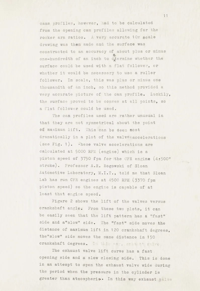
The cam profiles used are rather unusual in
that they are not symmetrical about the point
of maximum lift. This can be 3een most
dramatically in a plot of the valve(accelerations
(see Fig. 1). -hese valve accelerations are
calculated at 5000 RPM (engine) which is a
piston speed of 3750 fpm for "the CFR engine
(4:500"
stroke). Professor A.R. Rogowski of Sloan
Automotive Laboratory, M.I.T., told me that Sloan Lab has run CFR engines at 4500 RPM (3370 fpm piston speed) so the engine is capable of at
least that engine speed.
Figure 2 shows the lift of the valves versus
crankshaft angle- From these two plots, it can
be easily seen that the lift pattern has a "fast"
side and atslow" side. The "fast" side moves the
distance of maximum lift in 120 crankshaft degrees, the"slow" side moves the same distance in 150
crankshaft degrees. '1V
The exhaust valve lift curve has a fast
opening side and a slow closing side. This is done
in an attempt to open the exhaust valve wide during the period when the pressure in the cylinder is
12 blowdown may be more complete and pumping work
re-duced during the exhaust stroke. The valve is closed
slowly because it is felt that there is no real point in closing it faster.
The intake valve lift curve has a slow opening
side and a fast closing side. If the piston is
re-garded as a pump during the intake stroke and exhaust strokes, then maximum valve lift( and therefore max-imum flow area) should probably come at the point of
maximum piston velocity. In this design, however,
the maximuk flow area of the exhaust valve occurs
before maximum piston velocity in order to make best
use of the pressure in the cylinder when the exhaust valve opens. The point of maximum flow area for
the intake valve comes after maximum piston velocity
(see Fig. 3). Now, when running at high speed
the flow velocity will lag behind the piston
velocity, anyway, because of inertia. Since
this valve system is primarily meant fer
high speed operation, it is desirable that maximum flow area for the intake valve should occur after maximam piston velocity.
In reality, inertia and pressure wave effects can be so arranj2ed that it would be desirable to have the inlet valve wide open during its whole
cycle. This, of course, requires infinite
acceleration and is therefore impossible from a
kinematic standpoint. The intake cams, however,
could have had a fast opening side (120 crank degrees), a dwell of 30 crank degrees, and a fast closing side (120 crank degrees) without increasing
the duration of the lift. This would substantially
increase the maximum total load On the camshaft. If both intake and exhaust cams had had this profile, the maximum total camshaft loading would have been
very much larger, since this maximum occurs
during the period of valve overlap.
Valve timing must always be a compromise. The
large amount of valve overlap and large duration
period which allows adequate breathing at high engine speed permits flow reversal at low engine
speeds. Racing emgines generally have high volumetric
efficiency at high engine speed, but their volumetric
efficiency at low engine speeds is very poor due to the valve timing.
Desmodromic valve mechanisms have the
capability of reducing valve overlap and duration
period without any sacrifice in average flow area
by substantially increasing the valve accelera'tions.
The Mercedes-Benz desmodromic valve design operated
+ke eK9)IAe.
at peak valve accelerations of 1500 "g" andAhad a very flat torque carve over quite a range of engine speed with maximum volumetric efficiencies over 1000.
The valve timing used on the camshaft in this design is moderate in an attempt to make the engine
fairly flexible. V&lve accelerations are not very
high because of the large reciprocating mass involved.
5. Push Rods: The standard CFR push rods are lengths of
5/16" diameter round, steel rod w'ith the ends rounded.
Using'Euler criteria, their critical load (the load at
for
which they buckle) is about 890 lb & 6ngth-Appdoximately that required for the design. Now the peak load on the
opening pushrods is 7251bs. and the peak load on the closing
pushrods is 975 lbs. These pushrods are therefore inadequate
for this design. 1ew pushrods were therefore designed using
Shelby hard-drawn steel tubing (.,75" Q.D., .049" wall
thickness) with pressed-in ends. These have critical loads of 1310 lbs. for the opening pushrods and 1500 lbs. for the closing pushrods (which are slightly shorter).
4. Opening Rocker Forms: These rocker arms were originally designed to be made of steel, but were redesigned to be
made of duralumin. Steel inserts are pressed into the
end which contacts the valve stem to minimise waar. At
peak load, using a simplified model, calculated
maximum deflectionat the valveis .0072". The model
used is decidedly pessimistic and the actual maximum deflection
under peak load should be a small fraction of the calculated
valve. Liaximum stress occurs around the hole for the
pivot shaft brushing. Using a stress concentration
factor of 3, the maximum fiber stress at this point is
about 18,000 psi, well below the yield point for the
best aluminum alloys. The opening rocker arms multiply
the opening cam lift by a factor of twoas stated before. An analysis was made of the Change in lift ratio due
to pushod angularity and change in contact radius due to
rocker arm rotation and valve motion for both opening
and closing rocker armsto determine whether this
factor should be figured into the cam profiles. However,
it was found that the total effect was not as large, percentage-wise, as the machining tolerance for the cam
profiles.
5.Closing Rocker Arms: these parts are the sore point of
the whole design. They have to be rather long because
of the geometry of the engine, and the forked end concentrates
quite a bit of mass ataa large distance from the axis of
rotation. As a result, they have a large moment of inertia.
These parts were also originally designed to be made of
steel and were redesigned to be made of duralumin with
steel inserts at the contact points. Again using a
simplified model, maximum deflection at the valve was
figured to be .041". The model used here is very pessimistic,
but actual deflection may be about .(SZ5". If deflection
in practice proves to be larger than this, new parts should be made of steel with a slight increase in total reciprocating
mass. The closing rockers multiply the closing cam lift
by a factor of 3, as stated before. A sketch of the rocker
arm assembly is shown in Fig. 5.
6. Valves: the valves used are made by Thompson Products. They
have a face diameter of 1.32" (therefore the lift of .36" is
27% of the valve head diameter). The, stem diameter of these
valves is the same as he standard C F R valves, so standard valve guides may be used. The overall length of the valve is 6:' 3/16". This particular valve is used becausgt is longer than the standard C F R valvelbut weighs the same. The, extra length was necessary to provide clearance for
the closing rocker arm as it moves down.
7. Cylinder Head: the cylinder head used in the setup is a
standard removable C F R cylinder head. The only modifications necessary are to remove all obstructions on the top face
of the head. This involves moving the coolant outlet pipe to the side of the head, plugging the hole, and machining the valve guides off flush with the top surface.
8. Cylinder: the cylinder used in this design is a fabricated
cylinder with standard C F R bore (3.250"), originally used in some air compressor tests. The coolant outlet pipe must be moved because it interferes with the push-rodqland the base cut out somewhat to accommodate the guide block for the cam follower. These are the only modifications.
9. Springs: when the system is run as a semi-desmodromic system,
a spring has been calculated which has a free length of 1.25" (working length about 1"t). The spring constant is 575 lb/in.
The spring is precompressed to give a force of 150 lbs, which is sufficient to balance the inertia forces at 5000 R P M engine speed with as excess of 12Ibs. to take care of friction. If the friction is greater, the spring may be further compressed initially.
If it is desired to run the system as a three-quarter
desmodromic system, the above springsshould be replaced with
a standard spring which can be obtained from most spring
manufacturers. This spring should have a free length of
2" and should be able to be fully compressed without
set-ting((compression springs ardften designed on this basis).
The spring constant should be around 20 lb/in. At a
work-ing length of 1", this will give 20 lb. of force to seat
the valve. When running the system as a three-quarter
desmodromic system, the bottom spring retainers should
be replaced with the alternate ones which have been
17
COMPARATIVE LOADS ON THE CAMSHAFT
FOR DESMODROMIC AND CONVENTIONAL VALVE SYSTEMS
The camshaft is subjected to higher total loads than any other
valve train component. The camshaft loads are therefore indicative
of the relative load that any of the components has to carry.
Therefore, the total camshaft loads have been calculated and plotted
against camshaft rotation for the system used as a semi-desmodromic
system and as a three-quarter desmodromic system. In addition, the
camshaft loads have been calculated for a conventional system using
springs and following the same lift curve. In practice, this can
be easily done with the designed system by removing the closing
rocker arms, pushrods, and cam followers, and installing springs
to close the valves. Th spring necessary for this job should have
a freelength of 2 1/4". The initial compression with the valve
in the closed position should be 1/4"; a hardened spacer about 1/4"
thick must beplaced betweentthe spring and the cylinder head to
achieve this static load and prevent cylinder head wear. The spring
constant is 264 lb/in.
For purposes of comparison the cam loadings have also been
cal-culated and plotted for a fully desmodromic system of the
Mercedes-Benz type with an overhead camshaft. The same lift curve is followed.
In plotting the total camshaft loads, the forces have been
assumed to be all in the same direction. This is true in all cases
except for the fully desmodromic system where the' forces on the closing cam lobes are at about 90 degrees to the forces on the
opening cam lobes. For the sake of simplicity and consistency,
however, the loads on the camshaft of the fully desmodromic system have been piuAied as if they were in the same direction.
Figures 6,7,8,and 9, show the loads on the separate cam lobes when the system is being run as a semi-desmodromic system at an
engine speed of 5000 R P M. The loads on the individual cam lobes
when the system is run as a three-quarter desmodromic system are
5 kowti
1 3
(spring) load (40 lbs on the opening cam lobes, 60 6n the closing
cam lobes. Atlthe points where the inertia loads are negative,
there is no load on that particular lobe.
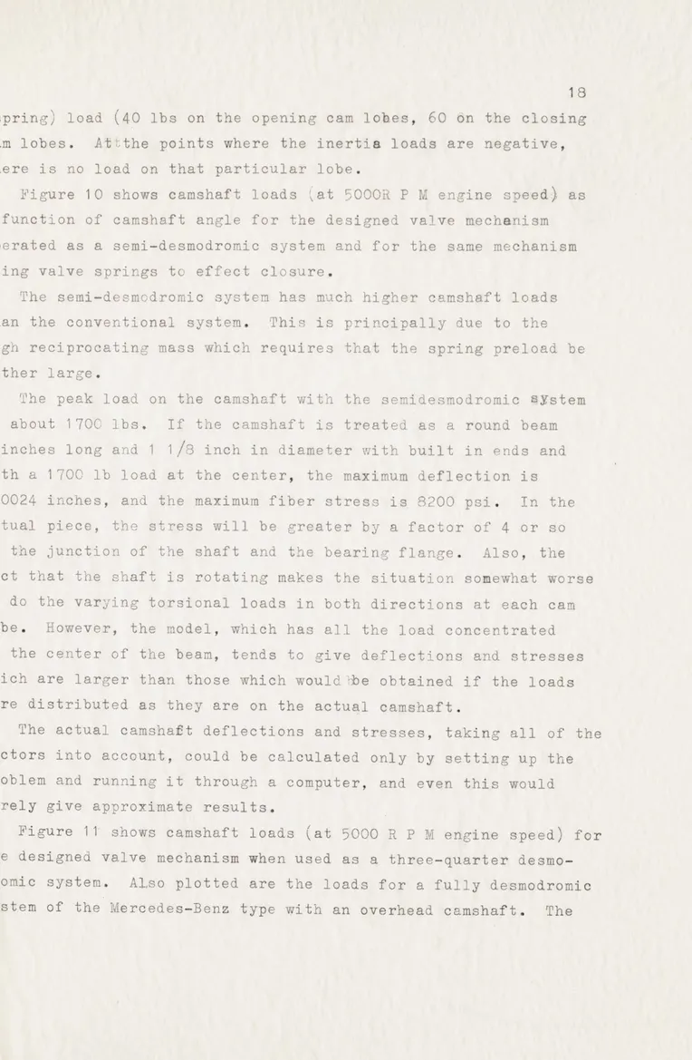
Figure 10 shows camshaft loads (at 5000R P M engine speed) as a function of camshaft angle for the designed valve mechanism operated as a semi-desmodromic system and for the same mechanism using valve springs to effect closure.
The semi-desmodromic system has much higher camshaft loads
than the conventional system. This is principally due to the
high reciprocating mass which requires that the spring preload be rather large.
The peak load on the camshaft with the semidesmodromic PYstem
is about 1700 lbs. If the camshaft is treated as a round beam
4 inches long and 1 1/8 inch in diameter with built in ends and with a 1700 lb load at the center, the maximum deflection is
.00024 inches, and the maximum fiber stress is 8200 psi. In the actual piece, the stress will be greater by a factor of 4 or so at the junction of the shaft and the bearing flange. Also, the fact that the shaft is rotating makes the situation somewhat worse as do the varying torsional loads in both directions at each cam
lobe. However, the model, which has all the load concentrated
at the center of the beam, tends to give deflections and stresses which are larger than those which would lbe obtained if the loads were distributed as they are on the actual camshaft.
The actual camshaft deflections and stresses, taking all of the factors into account, could be calculated only by setting up the problem and running it through a computer, and even this would merely give approximate results.
Figure 11' shows camshaft loads (at 5000 R P M engine speed) for
the designed valve mechanism when used as a three-quarter
desmo-dromic system. Also plotted are the loads for a fully desmodromic
calculations for this latter are-based on estimated reciprocating
mass for a system of this type mounted on a C F R engine, using
valves having the same weight, and following the same lift curve.
It, therefore , is a fairly accurate picture of the relative size
of the loads involved.
Figures 10 and 11 are drawn to the same scale, so direct
com-parisons cai be made. The curves are plotted on two separate graphs
only for the sake of clarity.
Comparison of the four curves shows that the semi-desmodromic
system is definitely inferior to the conventional system in this
instance, unless spring problems are present and can not be
elim-inated. The three-quarter desmodromic system, on the other hand,
has lower peak loads, despite all the added reciprocating mass. The curve of the fully desmodromic system is very much lower
than any of the others, and demonstrates the advantages of
20 DESIGN CONCLUSIONS
The designed valve mechanismican be operated as a
semi-desmo-dromic system. Indeed, all the stress and deflection calculations
are based on the peak loads encountered in hhis sort of operation,
to ensure that it would be possible to run in this manner.
However, if this system is built, it is advised that it be run as a three-quarter desmodromic because of the lower loads (and
there-fore lower wear)encountered.
If the system is run as a semi-desmodromic system, the spring otAsta:Wt
should be carefullyh hecked and the initial compression set carefully
in order to apply the correct preload.
If the system is run as a three-quarter desmodromic system, the
bottom retainer which has been designed for this purpose'should be
installed. T'he clearance between the opening rocker arm and the
valve button should be set at about .015" with the valve on its seat. The engine should then be turned over by hand until the valve is
lifted slightly off its seat. The clearance between the flanges
of the two spring retainers should then be set at .005". The engine
should be turned over completely a few times to check for interference
of any sort. It can then be motored at a range of speeds to make
sure that the spring does not surge.
In this case, spring surge may be caused by the acceleration of the spring, not by the relatively small displacement which i
it undergoes. Under these conditions, the vibrating mass is equal
to one half the mass of the spring, and the effective spring constant
seen by this mass is twice the spring constant of the spring itself.
For the spring described earlier, weight is .046 lb. and spring
constant is 20 lb/in. The natural frequency of surging is therefore
7800 cycles per minute. Since maximum camshaft speed is 2500 R P M,
only the fourth and higher harmonics of the motion have any chance
of exciting resonance. The amplitude of these harmonics is usually
small; however, if surging does occur, the spring should be changed and either a lighter spring, or one with a larger spring constant substituted.
GENERAL CONCLUSIONS
As stated before, it is believed that desmodromic valve systems
will be seen on production internal combustion engines in the future,
probably on the optional high performance engines which most
manu-facturers offer, and almost certainly on production sports car engines.
These desmodromic valve systems will probably be of the three-quarter
type. Very likely, the design will have both opening and closing
cams on an overhead camshaft, although it would also be possible
(and more desirable, on a production engine) to have two cams: an opening cam in the standard position in the crankcase, and a closing
cam in an overhead location, closing the valves by means of levers
IaumauamuI m suuIai~r~a
~ga
ma~
af~ua~uu ffo li 2 tolistuumna~****~.~* nI osmAn* a n Ki HUiMORH
.118 soL!~ W
~Uri
E3U
a CEUSH2UNE-umuw-a
~lUbUDDEWNU
DN USA:ua:s limits UN~~~~iNEUNDE148PRN~ UU33~na~lwia am u~uimm .WEumm~u~eiai
~3~
UERawl twuMss*NLWM 1 gas~ "up:Ew . U.uunsemi uuum aa0n4 *mmuN
~nn~aa~namma
um~sE EU~nJn V j.U.DM WV~f q 4. uugur-~~nq3~
'-.~uin a:: 11HII uuw~auminua~u~~nnmnn 5UMUm0UUEuUE 'S ue~P~-~ammauummmud.u~uUUUUUU cw.SSUlhWW u mumanuxmgw~ - U~~uu.UU.U t ona muOEMgmg2:9 HROESN ME1 11a am: a An .mmua~ Rival s11n ausmul A p nnsg 612 agogu us v7.mii wuu~antu Names~in Damao Afitl ammtil otuWaasumsmi Duu asaauanax nu Vll-alms msanam SOa suasmn~amua s Ma u $k& M-- aam a U 01 mug oOOO1BV fv S*KM wg d -cofoli even AX 1mS~ 21unussi ara sam
lu 4"oman & a m1.11111s may__llg vena~uesuu mPau -% m on~j a
inj
uf 1127 A MENmmmsA usuw 1 .SN -. uan uu m euuuuwm cmm msasm m~z smms ssmm aun am~~m was Susnniumiua i mallos unrmil as *11.1 u 10941 S was auasmm u ss USR sina a g!a na n u unu n
"nogoD asa.5 saaams go ti 3 % ammsuaras aa"umun snaa p u0In musaa H am Ama ER ulN 911141 Enumon Kill somel MEnmI u~s.saam umm saa uunm~aufuammut. w u s u 2*9mumau6%u"*suswsm~~ wssuuf~wa ama a aue mu.a so& Mu'r I
ummmljjt -w .1.m m lousmi~ -4umausnm s asumsnwunuu Stoasmmamanu Fa RogssSueNw mlla~m !SMA4 amaa"Imma a ua ** Img alBo mnuaamummomnounnall souasl aaus Bnsumm~mtmuURAsUsaa umunnamn aaasnrsu 3
m m a. tasmmnnmumam ummmauuanmmsmmAm uasmsnausmu U muausman~msaummmmmsa~gtmsmsamssnsmmuma. amuamsainanuwmssnsusumusmminssmmu ammm aunamssnutlfl
awasanD
msumuma usua0uaaaa a saumuuama5m9 uimso~aam~n wAu as an s m Uuflammaummuaumna iuumaamuuiiam assum SHIDsaa Nmm iSH: Rsswaam amuusale. ncaaammssussmsmumd ssm aNOaua a sau mmssums uumsaammsas~mmmunu smaummammma mmusmwsasummasvsn uin ulansaum
a S 11140 snan nm64un~ cymm : finmms~~al tm:mma 0111
ummmwaaammau Swumuua sMLNuNNau .aumuas Lemwus a Satmuim anum 'via, s-~ WEm~aamuU as Bmomau s" Me ins '..uasau .-msasnmmunumummrgun'amm~na,~xuuummss~
Snmusu~~a~ wnassxmn ams mns smuu oiluw Inmem Inauuamau i5mm INS!s H
~~.~mamssammu
a-m1 in asmmsPsasmwm :, a~ums~..a- .auaamsmaaanAmsw N.imansamsaaus' .~~t ausummusiaaAmsmm~amsa smmumrmmu~ausa'sad~~~smmmsma mmA~ uuma~aua~ga~
mummm ummam1mammnuaumaa mauumma smusolosaua~ amman
~
~
P E2-Eauusmmm mama um suusaaaa~ 0uu WINaamum ro~,I~m~ansm
umai umumu suffou anIRI an in a,, n N all. low mum> mnusasA 0 0 guaEsu.oEmms*aKnu 1m xwumluasauas f !Ksmns mv Mongolm.mnuum iusm nammmmmsuuum uss a sua aw alls uasnmiunsu a MR su. Sommermas nuuum umasIjmmssmmmuumam mmamaswsMa mnwm
~gsMan
aiw is mm Aus.am mamaam 'Lmrawuammm mmasuaummmsmu~u~msasam masmgsmnmusasmm onassmam mmuummausu~ ~
~ ~
~
~
~
~
~
~
~
~
~
~
~
omei sagas* masu Sammsamumu 0a smauzussqghamu usamaua! aa ao a0 IRmSw ImmuMi~mm~u INDwm muau~ss a muu m il a s w u matal ausssa um mmaasaam Woomm am m amugsuawwU~
PRO MR 1 RUu agmLamm ism me .aw a U e agImu notm a *mgumuss umna 01mmussa aua:l:mmlamsam amm~ usu~uf oluaa111mm m smas aamuu 9112NUm muau saa.u~mgaall, ala [w~uim ama.suimemmwAngmx~ masuumammsasmmmimmau
gssswsai Aua aam~mmusassanam u Masonaamumumu ausneaE m un as~namamuia imw a Samimau A smmaamama mm.ammamamuamwmnmmumaaaa ummuuaanamss mr usm1.22!ai msnamaussinsm~asmmsuuuma smammum~ anmammms
on ssssmmanumsmimumaau fmlumataamammamaanmuaiuaesmnmmauaamanf snsn aiu wa a mssi auuaas mmmuiuimam aismsmmm a wm ma a sni suam sa mw au~~u uiaum s au.magma msuaa mausm assm s amaum sn uns ;a~us mm~susmmaam amm NmURmuMsammmUumwa ssussas ama ewnaa ainu oxmu so7wam mimm ,asumnsaasms mu swaiamai nsmmmx uummnmmauwon mus aa'ammng NOWNnsamm. am Ori'.a maxx
uumsinmanmau annnuum suummmmm ammman un eous**# "Nauu n s mapsmasum ISM MRus~ am auvsgsamauaamausss-m..amm mmm~uiausminm.msuaumaa
VV;19un amu ssum wasmmmas m ua 13 mmsss sussIgasu n a 11:0. namus alaaas sm 1 m~s am as Wa u aa "a am~nsD ,sMRO SiMANS imau A M"*R Fanau AAum uin QmUINsN a aasoh. Ksms mamINES 19s $Romm mmn mma noq mamuismuanmmasmmm ma usmsatn nowmn-mma *041e Ma 90 101 "al min CH30 0aua~musm~umm~ 0 was lwa Nmusmm mssanm mmsi "Alhl ... 111"
us. Us~t aa masmin jamms amw ...
~
sLma mmm nsnmaflhEm
a
avuueummaaasassusagesmssaamasa as....aasaamaaiuassa saaaaiss aasmamsn aumxwaumuaannmsmussum marawam ainumuis muuuams~i
mas uuawmmuu as.umasnm *ms8sinamuns "I at malmunamw!! nim aamammasugs~amsimaunmauumaaasam a'isa unmanemil s umnu Kw us h mausmd mammuesummuma mmlumm~s
1 asm jmae ummnwcta -am.:mu !uu E S mam IRamm I maaiSuumsm mu WAuanie enus nalwuuum s 1~u mumuass a lzo "i ag aa sam nassasu s mmuama sis mimunsm ana ms aas uma asansm umma 0ms ina manmmmauam l[Iuaamm gumuuismman no nu"'mu xaas
411 main lo mil mau nsa Oil
moas uLinn..m lj U n aua
s m mmnmmanam s~ar amsasa E mi i4aai
Jmass aaa maammmm aa a~ u aIN ummnmmmm mammm amm rMu 1 uin~asss.ssmmsa mosum a u 11131l amwsw ,H:mm-.aa i- iummsimasumu*M~un aamssimit s -imam ms am iaumnosaio Naxosu
muss umainamuasm" ma au uO tomov AIUon He at US TAENUR ai uim muesnu~m
8!UM M aog a asaamamammma uKm141m sinu sum 31 m maagaa ln 3 am )N owl m~allsma~ fa11 A.,0 rtt I".RM GM 3 a 1n~ aul on Sol~5m3 5jngg.fl am
a n m
e loomsm uiOu munmansimu
3 GRAN earn am Mmari'a Ium Is SuEmM a
anmI rings m nom~smamma DE9~nI
111
mm Dm55.5mt asusam 3~ng m amamasas M ansinsna a ismm am musa Amumsmmuaunuaaisnma mmmgsuan mm mmsmuu smi s ummamusamaasu sma amama ,msmmmwnmsmJususamnIjamsanaE5D5smwsuusasmmmmma mm iu usaumIugummawuaamsmaaamnammu!a s m 1
nmIu Cr : 0in.maa i~u~~Em a 'msm.
~
s manm m uamms -amushssaallasamiu mmommaia m ammmam a m 5 ma t11 U uimuuumusu nmamumm~tmisnsnmmma~smminmgsuammgsimmREES - asnnmmsusua uasa 3mm uU~sasa~uun~sumsmmamsma asma,.aaauamamsinsasmaasmu~sm~sasu mmu.mauansasuammmamainsssaa us maga msu:Lg wng u in::nm 11 15~M ownssaam.4 ssa Saa an Imi Ila AmSmW
SRn I~lI! aln~l su9Meli smin uammspu mmom amanam mu al umintms inusmmmum lia5~ ajittms asum~wmi NmisUmK
us: HIM :H 1 1 m! ml~ aloa gaseoufftw inam a ,.uvxxwmg It, Iri in.a mumm m a an mml nij ui Amamumsmaxei in a s a m ma ma " inwm"R m91 13 "asm am .l mnas 111111s~m .rm.'sv
as allinmuausmnamsn.inusimi on ola..lon 3111i msnew IM ! Kil11
usswn man mKmSamsa M as Or log m i, n Monso ni usn mamma amaei sauuamam mumum m 'm s t assusuu 43 asnn ii 1 g ma m
~
~~
nsamaM.vnaamamusaa a mu 'u aas u.ua mga m sasmai mum us summu mmmnmlae 1mua n ninaimam
~
E [aa UNI sin INum~~ Nt~~~~~s~musmlamn a SHE mu lo umsua mm
u ama u mt um gmmammas. ma a mmos mmuop asj~m aaw an I'sbgsut ait~ R 6I*awp
ins M.um-a winnsus
m muss
ROM -a noma manm ma on",ama MINE * a l assou
atNH
*Ife:
H
l1uu!i0
u i
mnomlaaaml manw ma a an aa ma 5I:haJhma amaaafflm n aama mflamm n~man ' aWrmw'mmaaale ar .8maa,M maaamffl aamm aiailmaa mm ma na mammnla t mammam ammso m maRS al m-a agn man:I moaImmEIUULI wim
BONaNm ama 1aa mamma ma m mama m mmmamaaammmmm ll!
~
man on mavmm aoa amm Mmain am li---<~ua "a m I amlta main --O" A maw isma .m I.,u a aq
OWMN
mm w a ama mm aa a oa wnm on a aII a ME1 1W11l1 sun:a m a am amma a mame an. 0.mmmmmmma mae
aSOGNRylcsslsmans .0i a"a
mm l amae a *us m naw
~mf
m um a m maEmmaumnEsouin a mma "Immm t mm ma mwmma aam" amm~mam a19 maanmam aammmralla
'DdI
maus""m ImlOE nljlaa 2a10*:own
mamammama "illon :aaaamlmmmaaa Maxl~amaim a m mamamamaaa Mmm aine',a mama a lo a an a maa0 mama I HBO"aam ao amng" aamaammmaann amm 9mmammmmmmmm mam a1m amo mo~li l Rossa aammm amm 1 f~ifam hamaamnmamlmlmana a mama M a r man ar Ifm m~la~mama a 'qlahahimahm I . ama mm an
alaw llmimamgmammmmjlg_1 Iamaamilla maa
~
~
mama agam~hahighlaamlagama maana ammn~hmhgmaaniahmaa a mar mani a::m::~m :!!ifival i m a!::m
~!.~
mmammrmammm:mariamaammammon ia ammnamma :m mma m:L mamma Ial-am anm minimamammam mamalemmva ag
~
m upmaaaam mmaa mn q 1 W.ml maamaaa oasmmmaa pommm ilx Masm.maammma &a aaia~~~or
niluaam mamaam mamm amap Iammam Imaaamma immmammwmmaauaHiam amaaaaaa aaa. mmafaaalfilLmlimlaalammim mam m mflll aallalhama J mm manmamamammam aERa -m --- maaaamm mmaa aaa Aammmamma mn mamammamnamam
onaamm ammmmnnmmm manmaman amm mnaaaa ma 4 ammmmamams m: mm mm.amm ao mm md mmamm
nmaman mmail m ag maa. 11ii 0 ofimxamaaI :0immr, Irmlmamam~ama
manmamamKK malu nal a mammmamaua mama hiihmamnmmniia m amainan mmmmatmifllimmflam a maa ma mann a mmanam mmman m
amamaanonamHill-qmmr5 OWEa Rmmamnamma a
OamnaaaaamR*jaa aamm ammaaa
am am n
m mI m Im a m Zmmaama ama mamm Im aI maalalmam oamnm mamaammmm omammmmmmmmma mai 111:1 N' mm g s mamananmnmmu a
flowim Isaamim ammmmm Ham elfin Iam mamm aIn ama a aosoREF awGmam rin a mmmmameaammmm iilammmmnmama 111 maamm aaaaaa umm.m m amman a mmamn aa ma aiaa a A mm aam a mn ama mmnmmaaamfaamm mmmmmaimamaamammaanm *asmallmmaam
a S 8 e 's- an :amammamana msaman mama a cmn amnama maIRSmmnmm ma 1 am !amam ma m~mamLam aa amme3 aa soll 8mammummm a a amm a An am hamaia *mmaaaan amm m
mama mmnmv an W mamm aaamu a aamn m maamnam Nolaaamaaamm
ia IR aaamaa O.iaima ma .1 ma" usmmtmma aSaaamavmieanaa
mama ormamagsnmMmamnamama aanmma Nun um M a"X wnvmmo ama nnsWam n iama w anoamn anm
a a a ma m ma man mm a Mmm ammnaa m AlnV*mmamaa ONamam mam a Do a 9amma0i Sana a na mmaNliamill amma logo a1wC -mn- nna ama manna aa mamm IIaqlffga a mam amaam m mnanmmm aman amnmaa mmn amma mam maman
Evilsmam mmaa aami X nnIIII aaeaamma am mmm mi ulan m
asm"n ~lIma
I figR~am 7LNINE~w 1.' !:Mello HIn- 1,a Al ama as aanmamam ao ipasmalis a Sell Gomm ao iiflhiflaiamm am lrIUalH ____m araa.!: Wqi iiono R n ic
'
ma11 gglm ia a a a ama am m a1 N o Mns i" a a mamma mnamamma N~EEf~ a~ m am
Maa
Ill
~l~l
ag mmaNEm mamaII14
ajm-rmn
, Umax n am a a m aiau rm amn mmmI n Imm a af a unmammam m "s m m mmmaa ggsm gggn IImmma mam IS amamm iihhhm mamma* mana am a mm am amman
~xrlw
Hillma IWO SIR.namagogoawaalmammasal
a mannwnun an ignmmma am an a~
~
-nmmllilamquj~i HEama mama
a on l am:i~i aAWI mauanx a aam nihlnn=.~ 11hm1l~Ram mamaaauidmam=0
ZE NOl
~~
uE
~
iI a ma l~ m~~~~~
--Samo a onn Mel Bancomm Sos --anws "a :w 0n on IIona2In;I,mn man msa maIN. naam
111
film u 1mall:Sam inimmga4 a ma: a a an als mama man we namamamm
asJ
M gif amlAMna a Nibmgo maman am mam hf Bhifll.amam
aidma
mmINmalawa am'MOIS anma mm mama aRomaamn" amN
a
a maman,0Oln a a ma aS mnaaallaUm m m mamma mman anaanaaam ammmm asmm I
.00.. ft" awm uga amn mama19111 o 1 a 1 mm 51 11 iaammmnamaimmaama .2lx M, a "0 nw a "~ amm am "a a m a aimmammma ama m axo? Iam aa a mmaaaa nm m ummflama 1 aaal mm m a aa mm *mamm omufi r I 0m 1 1n!'o v aolINRCI I a: ina aa namormaaa mamma am ma mum a omm m anumama 0"60mammama manna asmmam Bama
mamma J In ui lilia~. 11, I::nmmaxualfu
Ii. mamaom momm la lm u"lg a m mmomummama49RPmroe
IS
am1111:Am "" a mm n m~l nam"Ir *~* on a~n wompoommoman *uNmmwmu;" g Uaows a in
.114
su.4.11. 1 -UUUUUU u~m.MUU1!ommo
samumona umu tom 0 :9 Nis. mman a *wu mm III! so 0 m u0 Ii!~I~m .;!Do:wn; UU maV mumu mm m u mm.. mum AM. a Itum auun H mi~ll~mol
mm
wamil
ner11MI
ansu is * ss u~ inumn .i:1 m m 1 1 pj11 r .mmuuiurI'tIkusMso
Ki f' uns 1111 man DU a~. I urn ammmass E HFill IN1D me Rol a'l 1 am~ U mu m Im N mmu w- _-m4 as muilmu m a MARN mmmmmrolog 1H T-wism OM *amal a Amos Ramapommean Noumea a OUROJAWjL an 0 lagoonman a mmun wasumumAka OWN muamn...upm 111 momsu mmmm 1mum .4.umpj so~u l mmnwr om m -dm mm m "mlnmmi11 ifII runmm anlli~ RinI 0~ mmmm u vlfl 61112 Bigm wal 114*11 Ia tr an mmi mum lipus:lreuu~~ 1m1.m*um~roIew
-m mumim mo tI~~n
111a g mm. ME Na mamam m ammnmnum ur winm .mum~
ff* i ummm mm ajmm aru a man mm uuw1 1IhL Pmmuuluill~~
H~m
u mu l ammmmm umuEN amim"uu~ ammin-pmrm HEm a MY ftmm"Immmuammmumiau m m mm u son" am we'a mi*mn O mo XOUII b.I aa~ a mm l~lflmmrnmma EU 10 t m l U m l 0- no Is mamm a uu a m ammmu m wiamum um mu M AIN umu IN~~mm mMR POmmuauINwmmu a1. 13 11 o t AMONG, g amm~mu mmamrmummgu an anmumom"jmA IN amunminn~
Omni 111 ONCE#::humnmaumU. imu Uiul~Ifm u M illrm uu ft no := planimu All.!: ' lo mm1,01 mm mu mu ma m amgal muC2 ua mm m mnmmmm mammmmu mm ummm u~. A m mmamuum wamm u ammmunummu umggmmumwmfmn an"u mim 01 m moin', 1IIIE 14 Imm rup aI ar Immmu~iEiUmmi~hmm um umuumumu a~I i dm mollmumlmm mmm mgaun-,mm W rum. Imnmmumm mas aM 9HH~ auur.II
mmuu vion mmmummmmul a 1104100WM8.4I umm611So .. w,! .uuuuuHE CAR l~E~m3 m 3gu~g~m mnmmmu . . m a IM a uam wmmaon ummni~U..nm m~
fl~ Alli iham m~.mljgi!
'00" Ha l Iam Ins, amI!!!lmm seemI!1 to W* am Uh u pfoniiv 0 gg Itmm mummggmm amNN sign~m m. uaua.mr U~l~l~fl m u~mm~on am rn in mmmmmmmmm amas.mm 1111' IimIIUIIIUIU mm muAm nnmm duumumil~lIim i: lima Oft A~. 112, am nmenn 111UsUa 0111"0104020 a~~~11IJl aI~iJ~:ihLiu
1111 mmmmu m1110c 400U P umj~j man1-:gjug4f mm sonmulfu mm mum. mumm aua-m mum N UH mmm mom ax mm mum* n NM al mm mmM aoaia~ am jg.jjjjjg ama wo u a jj1"flI mm a m m Imn mu_ 'U1ml lv -u~olo maqum Ion am a I Mason -aUhitIEIpi
*.Q1i
mINim mWmmmnumm
aa mm am :0gu.mu gikosgas 0u~ntMUa mo nammso am wm~mama alklmflm ma awa mamusm 3 o aa Iha wama ma mlm!l a n Monia .3 !auamo a-- :::hI aa! aiU uif ammuamaBeginammmaa mamuammmamamaamaamaaaa so Is lmma11 ma mm amama t.am1 "Mala mm am
m nx anamusM an amm man on aa mammam Jamesaaaammam Woaa MAIaE Ri... = gm 0
tie asoms am
a~ am
m9 lamEg 33 a asi mm~alai :alml! Ma:mn: 1 U: amm "MN anaagoaniv gamgma a immmammHmmaaa~mm a
~
~
~
~
~
~ ~
maaaa"ammaa an, m a mamma
~ma
amlbr mamx a 31 mu a am mmm ma aam maamanonaemma.himama mamaa m m maa maama amaHsia gjgmgmmma~aamm ag ammamaaamU mma m mm aumad mm a sfi m aaaamaamm aaammaag a ammmmu an aam mmmaaagamamm gammmaaaamemu a: a" m a aeo g am ma NOmaa am an ma4m:141 a
al: am ama a mamamamb1 Mmanoraaama aamsmaamIsaaaaamama a ASIN oAa aa mast amm m a am aumamamam amau EaMamaama M m mmmmmma U INam mamam% I ltPmmm onomnRs
GBU & an n maill~ a a a Ingi asmEam IBM: 1m ama amaa2 ma Mammmaa ammama DOESa if e i asjommma a
a
Billam am a11aNman WE.
am 11 to I ama
II~nlouuu
L..! mma mmm ma a m a It a00 ammamamas m. ama mama a eamRI aaa mmE NOEN am mmaaInmma amOmmmm mmli ammmaam ma omaammaavmnea ma mamma1 ammammma mamma ao III3Ha ammmm mama mas Ifuas"Wa asmm u maan anm mama aNaomaa a am Li m aamam Naa xosaamaam ma mmaa
mmm n a m~a m aa a Mamam mauma a maa m ammm aam m aamamammamm~aa
Egg
ammmaa aKi111 Ig.auii~a~i~ii~ a inn~iia !I msinw o main
mminm
~
111110ia ,aa a"ama "Aaa ma a e M emansaa a as Ia s a M fgm a mu maaa aBamnamm
~
amans mam a Vlai- am L ammmaa n minmmm mama t~ a ummama u-th aM a am aansmalm Willama amaaa asmaa mma aww MOaOmREmmm arn me m
a a m.m maammm amanmmm vanummaa am asma Lammaa mm a amman mamamamm
a" a m amma anm monooan a so ma Iammam loam wmu
rn sawAN ma maL;; maI - moe owningm amm enam mai no Noun *m"aBm q s 81 a a' 0mm amama -a mamm moma mAaamammmammaaa
amuu uslls manamm ma@ losItli a wa a amm almm wo-a INNE an
we13m~ m In manANa named amla
a am
IN nomaaammmm mamm ONE m am mamama a o am mi am11 mmaam aam iaa ' a m a aaaa HIMaa mammm maaa 111222
~
~ ~
~ ~
~ ~
~ ~
ammamma loop1 asue~ m am UN alalmammammamixn mam m m Sm a"
In t u m a Kil mmams amammamm ffmammmam amam.am
amosn meo mam auj monao .ama a ma atta 7.a,-g Itma
agmm Man ammmma on lazin aa mamain ama mam Siz: u *AL uhl kUl3ml ma~l~ m 3mim ama mumamaOt. ma.am mmmammm ofaaama
aa ama
am .B , mamw am"Nwn mmaa mama a mama asa al On...a ama aml a amamm uilaummaMamMe*awnmma__an aMaaamaa mmammam a as "oin areammno
unama
mammam mamamamm mma e::aa mamma~ox m u.mammmaa. a aamm
_ 1aaaam amammama aoo mamm mai mai .mmmmmmmaasl
mam amamiamammma man a mu F. a am 1mma MaMIN:m :mma
usHmaa asvm as ma w t& 1101 n111, umux mama1 ammamil ninon mg.aammm a~aapm.mm a 11aam mam Hillam mamn a ammamaammam .IN" mmnmmaalga M, g aamaaamammmmamauawineammmamam SoMINmama Kaamagjmo
lmama mm
mumma m usss u Nae a I as a w ma 1111"AAg ua. I* mam nees mamNEa minmam a va amma a a BCmaa~ama. -IN;-lmanau j] 7Wam ag mama ita mmalmr inmamnaama lif amai -- -- :r 7sma - - - mammaaa m ammanmmaana
Kim mila waxaminam oni m1011 a nw a mammea
~
Vai a none Am ,aa Isaama Itmmmm pum Of 91111miko m i~-i313:I 3I31 tiiih aamiinaaa Jmoainmm 0auma a m inmamaaaamamanmm amami ammamNN maam Iaama amammamin'A
mn inimmmami maaaa11aamma 1~m a maie ma ai m a
O'sama am mam amammaaena mmmmmaam l ma~ n 1'i"0um mamm a mmmmmuimmimman
Naommama
am, in ammu
aa
amnaaman a ME 1Ilh~ a mamm amma am ama ORaaaaaamamiammammmm iaama 0aa smmmailama mamma magso
a on
a a mgnamu*amaa a manm asi amaamn ama. mm mum am a sa w a amm assmamamamm mmaumamnaaammmamaammmammaamammaa amama
A maammamm aamaammal X mas" mm mam a a man ion amn a a a ina amm-m i a a owe
WE mW .0,2H;1asm ll: a m m o in amama a ainamm waamau:mauam mL m mam as Hishf I3N110: mmmiaa f
"'oan s*mamamamamm
am---
U1111 illll31oms
u1mi
Immma a X_3 a Am ama in fA mma a aalmallmunm aamm mamm ma am aa amm~'emua
Ran a main~minmaammauamamaaamam~naa mmammaain mam L~g~ amammamasma Dama low am
mm maagesm ma31UaaIB iIlJU
mi i Ia inma a n MISIO am man!E~aammm ama EaaiIi I
"am'Ii oa mainM asllllllI a a ma a am Be o C
~
ammuZamaam inamamin
1 aamll m a amm "11117A luimilam4lm a.l~~m eei am e asmmnaJ~um "UIaa N ao aaina~z~ sga "NN oamow 9nuta omo2 .me~ mmamumaa
31 mamajajmm-Vg m m m~~pjrAP-mui~~~~kmso mla amf 5 mma ain:lm aim am m maammmmaaammlIj
L is mon 9+4N I h Iaim a" a 11 a mm1m in. a am ono a 117.tk Or.... a NAME iigmw ma ama
Iaaa ammum mns ammma - a Aa a am mainn" O amaa maww onIansam ag mmm unmanm aM ag meam an Inai *Ros mNEWARK mow anme Go!m a NUNam mmwwalkauvxlo : wo Elms AN&*., Abas
ama Paloaamra .;Lrn aml"nlwnAt mamangteUK maam
mammaeMam i lsra a m A maM s
awaoo ponanom aN
rmmmol
mums 1111 In ma asawna :1ISOmh mall1 2 1 mua110 am ma an 14 m mas amaa mam a _aUmmm am ame aaau iamn nommmazmmmaiamma ama s.11a w an mmm as ai I"iulMlmmw"mpX a ma fl m m nuE IU m mm a i pse
I m mamma mammal so 1 mma i am mmmgm umana a~lm aaioa am am amanammmaimm nain aamma m m mmumm amos ma ia mms we 81111111 W=M a mannm m a oum l Rom sloganm
maaa--aamamammamaaamm am a mai IN a mm mina a mam w as a m
a a a ammf ali ma amamm ma
IlI