MITLibraries
Document Services Ph: 617.253.5668 Fax: 617.253.1690 Email: docs@mit.edu http://libraries. mit.edu/docsDISCLAIMER OF QUALITY
Due to the condition of the original material, there are unavoidable
flaws in this reproduction. We have made every effort possible to
provide you with the best copy available. If you are dissatisfied with
this product and find it unusable, please contact Document Services as
soon as possible.
Thank you.
Some pages in the original document contain
by
Courtney Browne
SUBMITTED TO THE DEPARTMENT OF MECHANICAL ENGINEERING IN PARTIAL FULFILLMENT OF THE REQUIREMENTS FOR THE DEGREE OF
BACHELOR OF SCIENCE AT THE
MASSACHUSETTS INSTITUTE OF TECHNOLOGY
MAY 2004
© Courtney Browne. All rights reserved.
The author hereby grants to MIT permission to reproduce and to distribute publicly paper and electronic copies of this thesis document in whole or in part.
Signature of Author:
Department of Mechanical Engineering May 5, 2004
Certified by:
Alexander Slocum Professor of Mechanical Engineering Thesis Supervisor
Accepted by:
Ernest Cravahlo Professor of Mechanical Engineering Chairman, Department
MASSACHUSETTSINST1
OF TECHNOLOGY
OCT 2 8 2004
LIBRARIES
Committee on Undergraduate Students
I
ARCHIVES
by
Courtney Browne
Submitted to the Department of Mechanical Engineering on May 5, 2004 in Partial Fulfillment of the
Requirements for the Degree of Bachelor of Science in Mechanical Engineering
ABSTRACT
The deterministic design process taught in MIT's 2.007 course (Design and
Manufacturing I) can be applied to many design situations. After taking the course, Browne developed a robotic car which has an articulated suspension. This car is a simple design that could be very useful to students in the 2.007 course; the robot cars
made in this course often have a solid base which makes it difficult to drive over small obstacles. In addition to being easy to manufacture and assemble by students in the 2.007 course at MIT, Browne's design addresses this problem. It also is a generic car that could be used as a base for many other interesting and useful mechanisms a 2.007 student might design.
Thesis Supervisor: Alexander Slocum Title: Professor of Mechanical Engineering
1. Introduction
Every spring at MIT, many students register for 2.007, Design and Manufacturing I. This course, with its unassuming name, is one of the most popular classes at MIT for one simple reason; students get to build robots. Although many students have high goals for what their robot will achieve, in reality, most robots get stopped by the simplest obstacle. For instance, when there is a feature of the course which is elevated above another, the robots can rarely drive over this impediment. Even misplaced balls and pucks (which are often used as a means to score in 2.007 competitions) can cause a
robot to become trapped. Therefore, these ensnared robots are doomed to futilely spin their wheels until the round is over. Therefore, Browne, a 2.007 student from spring 2003, decided to address this problem in her undergraduate thesis. She employed the deterministic design process taught in 2.007 to build a multi-purpose car with all-terrain
suspension. This car would be able to drive over obstacles of various heights. In addition, as the project progressed, it became clear that this design would be useful to 2.007 students in the future. Therefore, Browne endeavored to make her design so that any 2.007 student could construct the articulated robot with provided kit materials.
2.
Strategy
The first step in the deterministic design process is to develop a strategy to address the stated problem or functional requirement [1]. For Browne's thesis, the functional requirement was clear. If a 2.007 student decides to build a car as his or her robot, it is often simply a solid base plate with four wheels mounted on the plate. This works well until the car encounters an obstacle of a different height, such as a puck. A
robot might need to deposit the pucks in a collection bin in order to score. Sometimes these pucks are stacked on the competition table. If a car topples the stack of pucks, the pucks will fall all around the robot, and the robot may become trapped. If the car attempts to drive over the pucks, one of the robot's wheels will surely loose contact with the playing surface. If this wheel is one of the wheels coupled to a motor, the robot might not have enough motorized wheels in contact with the playing surface to be able to get back down.
In order to solve this problem, Browne developed a strategy that solved the previously stated problem. If a car were able to maintain wheel-to-playing-surface contact at all times, it would be operating under ideal conditions during the entirety of the competition. Therefore, the car must have a suspension system.
3. Concept
The next step in the deterministic design process is to generate a concept, or design parameter, which will implement the strategy. The concept consists of the actual
mechanism which will achieve the strategy [1]. The concept which Browne developed includes a central shaft which allows the two wheel axles to rotate independently in order to allow four-wheel contact of the playing surface at all times.
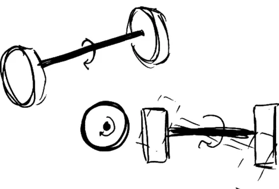
More specifically, if two wheels are attached by a common axle, and one looks at the center point on this axle, it is obvious that the axle can spin two ways. It can spin about the axis of the axle, or it can spin about the center point of the axis (Figure 1). Although the wheels will always spin about the center axis of the axle in the same way, the other degree of freedom depends on how the axle is attached to the car's frame. If
the two axles are allowed to move independently by the means of a central shaft that is attached to each axle's frame, then the wheels will be able to rotate in order to
accommodate obstacles, like those in a 2.007 contest.
4. Additional Concept
When developing concepts, it is useful to develop many mechanical solutions to the same strategy. One way to develop additional concepts is through research of
existing mechanisms which accomplish the same goal. Therefore, Browne sought out new concepts through research.
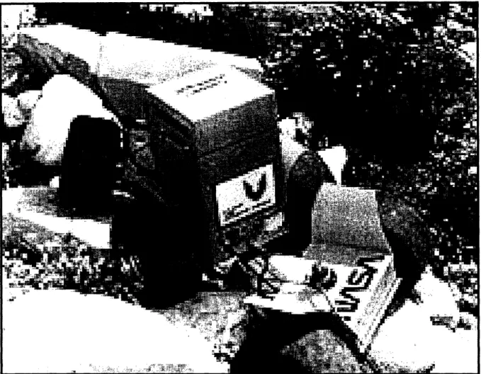
During early space research, a rover was needed that could traverse the uneven terrain of foreign planets. Therefore, a rover was developed with a "3-Segment" design which allowed each segment to move independently relative to the other segments (Figure 2). This allowed the rover to drive over uneven terrain while its wheels maintained contact with the ground, giving the rover more stability. However, this design was large and cumbersome [2].
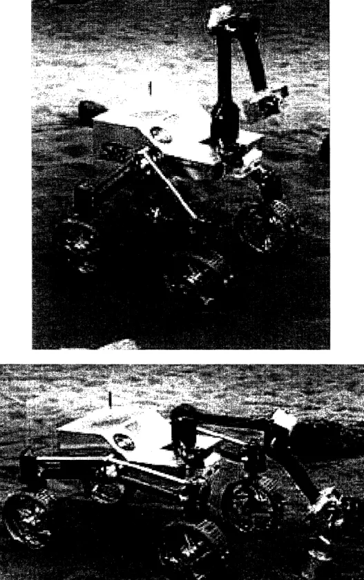
Later, other designs were developed which were smaller and more effective. For
instance, more recently the SSR (Sample Return Rover) was developed by JPL (Jet
Propulsion Laboratory) in California. It has a two shoulder joints that can be actively
changed to modify the rover's center of mass, and thus allow it to traverse uneven
terrain (Figure 3) [3]. This rover also has an articulated suspension that accomplishes the goal Browne established for herself in her thesis.
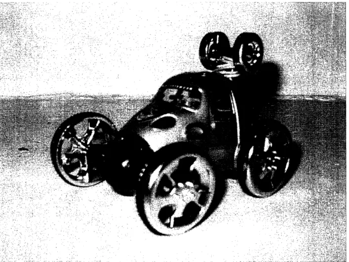
In addition, there are examples of articulated suspensions in the toy world. One such example is a toy car that has a central axle, which is driven by a motor (Figure 4).
This motor allows the car to flip the direction its wheels are facing and, thus, quickly change directions.
Although these concepts are all very interesting and novel, Browne felt that they were either too complicated for her purpose (in the case of the two space rovers), or
they addressed a different issue than the one she was trying to solve (the toy car). A passive center shaft would accomplish her goal of allowing 2.007 robots to drive over obstacles.
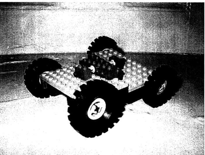
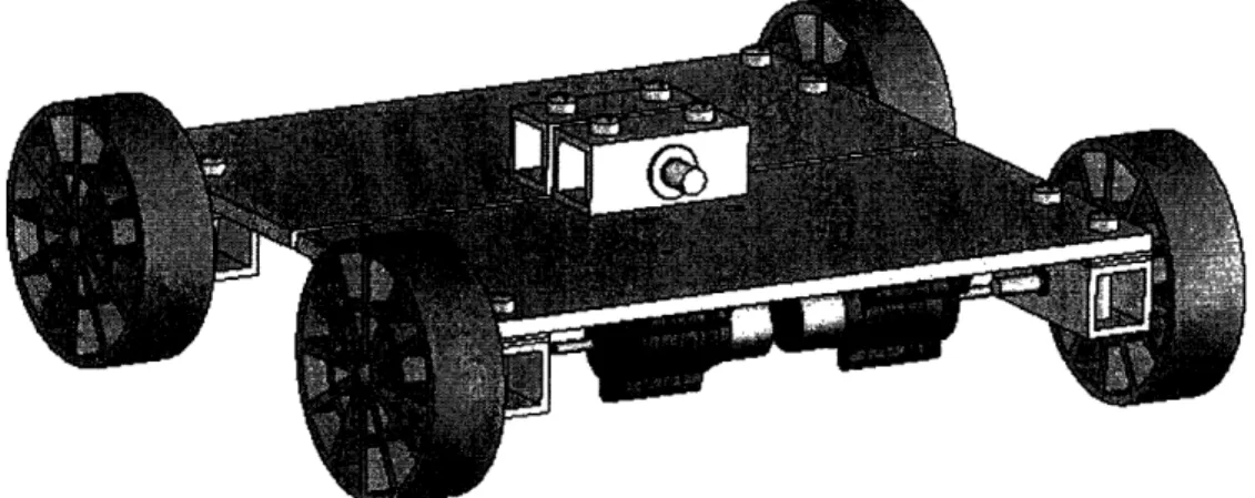
To determine the basic structure of the final design, Browne used LEGO building blocks (Figure 5). A simple design quickly emerged which could also be easily built with 2.007 kit materials. To further refine the idea, Browne built the robot in Solid Works to make sure that the parts would fit together as she envisioned (Figures 6-1 1). This was a straightforward design which included four motors that could be added or removed
depending on the end use of the car.
5.
Two-wheel-drive versus four-wheel-drive
In the 2.007 competition, many students decide to build cars that feature "four-wheel drive." This characteristic is desirable because it can provide more
maneuverability and stability. In the context of 2.007, "four-wheel drive" simply means that all four wheels are supplied power. Although coupling each wheel to a motor is one way to accomplish this task, this method leaves no motors for other functions (a
maximum of four actuators are allowed in the competition). Therefore, students often build a gear train to couple two wheels to one motor.
However, an ordinary gear train will not work with Browne's design. The distance between the wheels will be variable depending on whether or not the car is driving over an obstacle. Therefore, a system is required which will allow for this variable distance.
Browne designed a belt drive that would couple two wheels together so that only one
motor was needed for two wheels. For the belt drive, Browne decided to use a rubber
band (Figure 12). This would allow the flexibility needed for the variable distance between the wheels.
6. First Peer Review
An important part of the deterministic design process is drawing upon a
colleague to critique ones design. This is known as "peer review." For Browne's first
peer review, she consulted Alexis Weber, one the teaching assistants for the 2.007
course. He liked the idea of having four-wheel drive with only two motors, but he
thought that Browne's rubber band idea might create problems. Weber felt that the efficiency in transferring the power from the motor to the wheel which would not be directly driven by the motor would be low. Thus, the wheels might not run at the same rate, and the car would have unpredictable driving characteristics.
Therefore, Browne and Weber developed a concept which could drive the wheel not directly connected to the motor through the central shaft of the car. It involved gearing which would run through the central shaft. A worm gear, running the length of
the car, would mesh with a regular gear, attached to the motor. This mechanism would
drive two wheels, also connected through gearing. For this concept to function properly, two worm gears would be necessary. One would be thinner, longer, and run inside of
the second larger, shorter worm gear. They would both be mounted, by means of ball bearings, in the center of the car, thus acting as the central shaft and gearing system all at the same time.
Although this design is innovative, it cannot be easily built using 2.007 kit materials. It would require the manufacture of a specialized worm gear and bearing. Parts that require extensive machining with tight tolerances would be difficult to manufacture by a student with little machining experience.
Keeping in mind that Browne's goal was that her car could be built by any 2.007 student with little machining experience, she felt that the time necessary to manufacture the gearing module would be much to long to justify the added gain in performance. Therefore, from review session with Weber, Browne decided to go with the easier concept: two-wheel-drive. She would keep the four motors on her car as an example to 2.007 students of where they could be mounted, but for testing, she intended to run two
motors at a time. As a contingency plan, Browne decided that she would make
modifications only if after building and testing her robot she felt that four-wheel drive was necessary.
7. Second Peer Review
After the car was built, Browne showed the car to Fadi Ibrahim for another peer review. Ibrahim has done research on the performance characteristics of the Tamiya motors used in the 2.007 course. When Browne consulted Ibrahim, the wheels of the car were coupled to the motors by means of a flexible coupling. This method of coupling was invented as a quick solution for coupling motors in the 2003 contest. In
the 2003 contest, Tamiya motors were used for the first time. In previous years, Black & Decker drill motors were used. Since the drill motors were so much more powerful, the Tamiya motors behaved quite differently when subjected to side loads (they often locked up). Therefore, a need to mitigate the side loads arose. This need was fulfilled by the flexible coupling. Two shafts (one from the motor and one from the wheel) were press fit with plastic, flexible tubing. This tubing was then wrapped tightly with a fine wire. Although this method did solve the problem of reducing side loads, the efficiency was very low. The wheel shaft would often slip within the flex coupling, despite the tightly wrapped wire. In addition, the flex coupling's performance decreased over time.
Eventually, the strain on the wire became too much, and the wire broke, completely negating the role of the flex coupling.
To solve this problem, a new "flexible" coupling (Figure 13) was developed by Professor Slocum (instructor in charge of the 2.007 course). This became known as the "low-cost coupling" [1, p.29]. This coupling prevented the motors from being subjected to side loads as well; it only transferred the torque from the motors. Once Ibrahim saw
Browne's machine, he quickly suggested that the new couplings be used.
However, the wheel bearings were made to accommodate the old flexible couplings. In order to use the new couplings, the height of the wheel shaft had to be raised. Therefore, spacers (Figure 14) were manufactured to adjust this height. (See
8. Testing
Once the new couplings were installed, Browne performed tests to verify that the articulation of the car would perform as she had designed it. She connected the motors to the power supply used in the 2.007 contest and attempted to drive the car over a
21/2-inch-tall foam block. The test was a success. With four-inch wheels, the car easily surmounted the obstacle.
Next, Browne tested the speed characteristics of her car with Xue'en Yang, Professor Slocum's graduate student who provides technical support for the 2.007 course. For these tests, Browne and Yang used disposable batteries as the power source, since they have been the power source used in previous years' contests.
A Matlab simulation was developed by Professor Slocum's graduate student, Jian Li, to help students predict how fast their cars can run. First, Yang ran this
simulation to predict the speed of the car with parameters provided by Browne. These parameters were determined by direct observation (number of wheels, number of motors, gear ratio), measurement (weight, diameter of wheel, coefficient of friction), or through Solid Works (moment of inertia of the wheel). Figure 16 shows the user
interface of the Matlab simulation which allows the user to plot speed, distance, energy, and torque versus time (Figure 17).
Next, Browne and Yang ran two real-world tests, one in which they stopped the
car at approximately 25 feet (7.8 ±+ m), and another where they allowed the car to run at
full speed for 15 feet (4.68 +± .05m). As is apparent in Figure 18, the actual data and the
experimental data are quite similar. The discrepancies can be explained by the path the car took (not perfectly straight, due to slight wheel misalignment), and the fact that the
simulations do not take into effect air dynamics or battery drain. These simulations and test show that the car will perform well in a 2.007 contest because it can move 15 feet
(nearly two contest table lengths) in about five seconds (the competition rounds are 45 seconds long). These results further validate the decision to use two-wheel drive, especially since the two-wheel-drive car can easily surmount an obstacle.
9. Modifications made for the 2004 contest
After the car was built and tested, Browne learned that the 2.007 kit contents had been changed for the 2004 contest. The wheels that she used to build her car are not available to students for the 2004 contest. Therefore, Browne made modifications to her design so that the current 2.007 students could use the new wheels. She changed
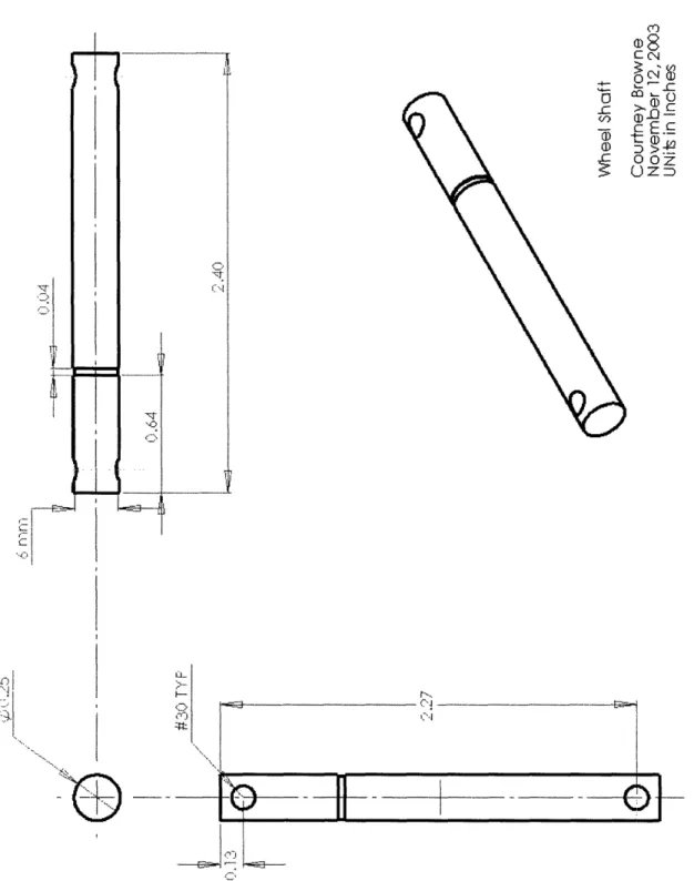
the wheel shaft to accommodate the different wheels. Browne determined that a 1/4"
hexagonal shaft could be press-fit into 1/4" round hole in the 3" wheels provided in the
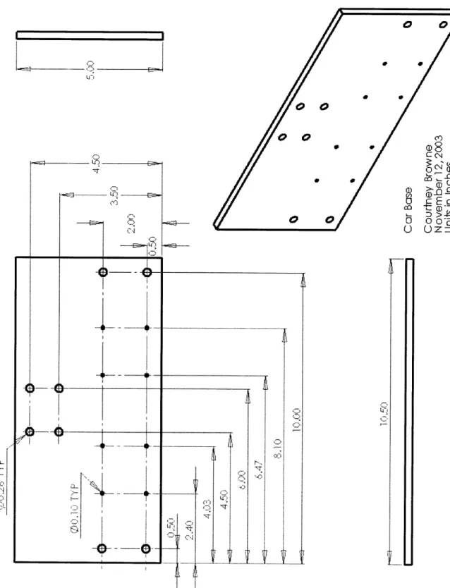
2004 kit. Therefore, a new wheel shaft (Figure 21) was designed which could be press-fit into the 3" wheel to couple the wheel's motion to the shaft, but still constrained so that the wheel would not slip off the shaft. Furthermore, Browne included slots instead of holes in the base plate so that students could choose which gear ratio to use in their design (Figure 20). Changing the gear ratio might require additional gear
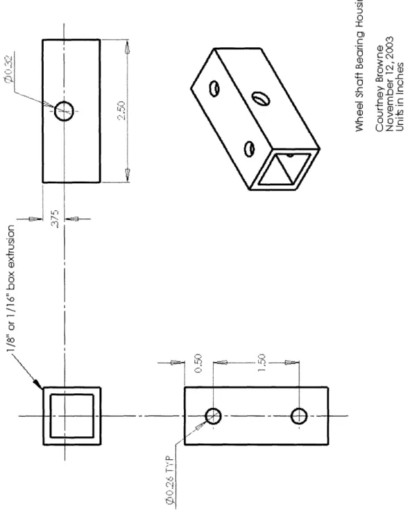
housings, which would increase the length of the motors, making the slot necessary. Finally, the wheel shaft bearing housing was modified to accommodate the low-cost couplings and to eliminate the need for spacers (Figure 22).
10. Fabrication
For the students enrolled in 2.007 in spring 2004, Browne wrote the following instructions. After all of the parts have been made (Figures 13, 20-24), these
instructions will guide a student when fabricating the actual machine with available kit
materials. (For a bill of materials, see Figure 25.)
* Press fit the wheel shafts into the 3" plastic wheels so the transition between the hexagonal and round shaft lies flush with the face of the wheel
· Insert the M6 nylon spacers into the wheel shaft bearings
* Insert the round portion of the shaft into the nylon spacers * Put the 6 mm E-clip in the other groove
* Use the arbor press or a vice to press a spring pin into the hole in the wheel shaft * Repeat 3 times so that you have four wheel assemblies total
Slide the low-cost couplings on the end of the shaft so that it slips over the spring
pin
* Attach the motor to the base plate. Slip the assembly onto the output shaft of the motor so that it slips over the spring pin. Secure the assembly with 10-32 nuts and bolts
* Slip the M8 nylon spacers into the suspension shaft bearing
Slip the suspension shaft through both of the suspension shaft bearings and secure with the 7 mm E-clips
11. Conclusion
By using the deterministic design process, Browne developed a robotic car which has an articulated suspension. Due to this process, this car is a simple design that could be manufactured and assembled by any student in the 2.007 course at MIT. It also is generic enough that it could be used as a base for many other mechanisms that a 2.007 student might design.
12. References
[ 1 ] Slocum, Alexander H. Course Lecture Notes for 2.007: Design and
Manufacturing . Available online at http://pergatory.mit.edu/2.007
[ 2 ] http://www.maqneticpie.com/LEGO/roverHistorv/roverSize.html [ 3 ] http://robots.mit.edu/projects/nasa/index.html.
13. Figures
Figure 1: Degrees of Freedom of a Wheel shaft Figure 2: Segmented Design
Figure 3: Rover with articulated suspension
Figure 4: Toy Car Figure 5: LEGO Model
Figure 6: Original Solid Model Figure 7: Original Car Base
Figure 8: Original Wheel Shaft
Figure 9: Original Wheel Shaft Bearing Housing Figure 10: Original Suspension Shaft
Figure 11: Original Suspension Shaft Bearing Housing Figure 12: Belt drive design
Figure 13: Professor Slocum's low-cost coupling Figure 14: Spacers
Figure 15: The Prototype
Figure 16: Matlab simulation interface Figure 17: Matlab results
Figure 18: Testing versus simulation results
Figure 19: Final Solid Model Figure 20: Final Car Base
Figure 21: Final Hexagonal Wheel Shaft Figure 22: Final Wheel Shaft Bearing Housing Figure 23: Final Suspension Shaft
Figure 24: Final Suspension Shaft Bearing Housing
Figure 1: Degrees of Freedom of a Wheel Shaft
Figure 2: Segmented Design
. , I I ll., I',- ".4% W I
""
I,
Figure 4: Toy Car
.~ ~ ' .. . :~;. -. : .~ i ,- :. , F¥ '
>;?
Ar. iX.. , ',.; xH~'? ,../i .7 .. .. A
alar>~ ~ ~ ~ ~ ~ ~~~~' ".~~..:~'' . '. .:;-, i~;? i'
' .'!~.~:~
i i" ~~,~i~:~~
i?!~, 't
:';
'
Figure 5: LEGO model i~~
~
~
4 , -W -. 'v'3g,-gs ... ,:. ;'-; ' ... . ,, , 47 2% ;~ '..,. ,. +:'i ' .,· ,.i:, , .,, , . .; .,,; ,_ ,'. ' . ,' f.''' rC ,¢",, , ' !i'' In -47 2 7 7 .,,,Figure 7: Original Car Base
I
toN~~~~~~~~~~~~~~~~ F=-L we
LI-Figure 8: Original Wheel Shaft I
,o
C )N C ~c . E .? O-r--o O-r--oZ C) Z ... 6--I.-I I Oi ,D I, I I I I I I .tv C', 'T (-,jFigure 9: Original Wheel Shaft Bearing Housing 0) 0 I 0)~~~~~~~~~~~~~~~~~~~~~~~~~~~~~~~~~~~~~~o kN4 '..f) C_ 47 C 0 'G75 .4---c 0 x O0 -. ~o c ~ I wo (D C N c- -0 -=D D'> 3: Uz Z _ ) ~ u3 I I I Q tiff C-1 Lq, N rID w t
Figure 10: Original Suspension Shaft --i-I
1
l Il I = ;-' CAI L© O _c oY) c-1 co~ C M C - C N < n E Zo - U CzD L1. 8I-' I]I, X~~~~~~~~ -- ---if. - --- -- ..-. - [ - - L i i ---.- i - z _...__.__~__ I CL-, I ,,- I .i -Z,,I-C',0
Figure 11: Original Suspension Bearing Housing c .C D 0 C O Q) C c -° o,1 Q o o : 0) z Q/) t1y D c E Vr - +- O 0 -tc) OD >-c 0 D x Q) x 0 10 .Q-6 ~o O Ij
Figure 13: Professor Slocum's low-cost coupling E ) 0 _C:
c-0
__x XO~ 0 o, ~
n.--OEC 0 (D D 'lIzIII... ... I - 1. I - -- 12_1, i ... ._..`F
1IFigure 14: Spacers co (D O c' O a.
On:
~ (DOc OO -> aD I. -( C-, II-L -.-
---- F-Ij III EFigure 16: Matlab simulation interface
Gear Ratio Optimization for Driving A Car
Inputs
Gear Ratio:
Secondary Gear Ratio:
Number of Wheels:
Number of Driving Wheels:
Number of Driving Motors:
C 1:16 ¢ 1:20 C 1:25 C 1:100 C 1:400 4 4 t 2
Rotational Inertia of One Wheel [kgxm'2: 7.1e-5
Car Mass [kg]: i 2.472
Wheel Radius[m]:
Dynamic Friction Coefficient: 0.0401
Static Friction Coefficient:
Push Force [NI: :N 0
Desired Distance
[ml:-Drive Train Efficiency:
Motor Resistance [ohm]:
Outputs
Acceleration Time [s]: 1 Total Travel Time [s:
Constant Velocity Time [s]: [ Peak power [W]: 21.672
Deceleration Time [s]: 4 Total energy 1J] [512
Figure 17: Matlab results
Plot of Overall Torque vs. Time
i ; l l _ I i I4-- - - - - -- -- - - -i i i i ... . ,i... , i
0
20 40 6(Plot of Tistantevs. Time
0 2 4 Time [s] -0 E a) CL cor 6 8 -0 2.5 2 1.5 1 0.5 0 L
Plot of Speed s. Time
2 4 6
Plot of [siime
Plot of e nergy rs. Time IUU 80
;-
60
40 LL 20 nu 2 4 Time [s] 6 0.2 Ez 0.1
a)I E 0 0 F--z -0. 1 I---0.2 4C1 I A '- -- - -- I- - -'- - ---- --- - - - --- ~~ -- -- i- - I I ._ ____ 4 4___V___ E 10 -, 0 Ic.u 4' 5 . _ 6 n 8 8 I o ~11,,Figure 18: Testing versus simulation results
Travel End Travel Time_ (s) _
Distance (m) Condition Experimental Matlab Simulation Excel Analysis
_ _ __I _ _ __A ~ ~~~ ~ ~~~~~~~~~~~~~~~~~~~~~~~~~~~~~~~~~~~~~~~~~~~~~~~~~~~~~~~~~~~~~~~~~~~~~~~~~~~~~~~~~~~~~~~~~~~~~~~~~~~~~~~~~~~~~~~~~~~~~~~. .... Stoppeda 7.8 0.1 IStopped at 6 0.2 6.36 7.73 end~~~~~~~~~~~~~~~~~~~~~I _ 4.68 +0.05 Nostop 5.2 0.2 4.1 4.24 e nd _ . . .
_
. . ._
_
_
Figure 20: Final Car Base
I I
,:D,
:I- C --
Figure 21: Final Hexagonal Wheel Shaft O) 0 0
a
c E C I-. -4-E .c 4--1:7 E) X i .'As-C)
i I3 '0 0 a) c Or
go
3:O ~ ( C o3-)O~o-2
(
o ©) .w=0 o '~: © D 4 -r -1 I b~ ~
~ ~ ~
.. I.....i II ( I (Figure 22: Final Wheel Shaft Bearing Housing CD c 0
I
'-i _ A~~~~~~~~~~~~ ___ C#~~~~~.I~
~
~ ~ ~ ~ ~~~~~~.
"
i] LOD 0 © 3 Co a Oo m- 0.
c >- C a)-k
Uu-n
C 0 2 .0 D x 0) 0 oD C) LO ,__j
I ---,4 I I.-Figure 23: Final Suspension Shaft C) 0 C-c 0 co C rn Vi D 60 Co (D I-CO o O~C 0 O C--ct D O-L- o0-F I,J I C'-1 *~ I,::
'0
-
-t
iI RFigure 24: Final Suspension Shaft Bearing Housing O) -.0CD 0 0) C 0 0 D x a) x 0 _0 Co~ 10I I II ',O co -I-0 -C c
0
o '~ C,, Q2) n COC4- D.-- Uo -d C c" .ULLuFigure 25: Bill of Materials
4 x Tamiya motors
2 x car bases
4 x 3" plastic wheels
4 x wheel shaft bearing housing 4 x hexagonal wheel shaft 8 x M6 nylon spacer 4 x low-cost coupling
4 x 1/8" spring pins 4 x 6mm e-clip
2 x suspension shaft bearing housing 1 x suspension shaft
4 x M8 nylon spacer
2 x 7mm e-clip
12 x 10-32 bolts 12 x 10-32 nuts