DESIGN AND DEVELOPMENT OF A THREE
DIMENSIONAL KINEMATIC SIMULATION,
STEERING SYSTEM AND SCIENTIFIC
INSTRUMENT DEPLOYMENT MECHANISM FOR
A PLANETARY MICRO-ROVER
by
Shane M. Farritor B.S. Mechanical Engineering University of Nebraska-Lincoln (1992)
Submitted to the Department of Mechanical Engineering In Partial Fulfillment of the Requirements for the Degree of
MASTER OF' SCIENCE IN MECHANICAL ENGINEERING at the
MASSACHUSETTS INSTITUTE OF TECHNOLOGY May 1994
© 1994 Shane Michael Farritor All rights reserved
0r A2~N
Signature of Author
Department of Mechanical Engineering May 4, 1994 Approved by
---o/ by Dr. David S. Kang
/ Ii 'Technical Supervisor
Certified by
Professor Warren Seering Thesis Supervisor Accepted by MASSACHW*%.'4 1'SN0L
AU~ Qj~8
7'r_
I
1 I~'V!Professor Ain A. Sonin Chairman, Department Graduate Office
DIMENSIONAL KINEMATIC SIMULATION,
STEERING SYSTEM AND SCIENTIFIC
INSTRUMENT DEPLOYMENT MECHANISM FOR
A PLANETARY MICRO-ROVER
by
Shane M. Farritor
Submitted to the Department of Mechanical Engineering In Partial Fulfillment of the Requirements for the Degree of
Master of Science in Mechanical Engineering
ABSTRACT
Three separate topics in the design of a planetary micro-rover have been investigated including the design and development of: a three dimensional kinematic simulation, a steering system, a scientific instrument deployment mechanism. The simulation models rover motion and sensor readings as the rover travels over various terrain. The simulation is used in the evaluation of the rover's hazard avoidance software. The steering system investigation explores three different types of steering for a rover with conical shaped wheels. These three types of steering include tank steering, steering using wheel speeds, and a hybrid steering system which uses a worm gear as a locking mechanism. A two degree of freedom deployment mechanism as been designed and built to deploy a scientific instrument from the rover. This design investigates different compliance techniques to improve instrument positioning in an unknown environment.
Technical Supervisor: Dr. David S. Kang Thesis Supervisor: Dr. Warren Seering
ACKNOWLEDGMENTS
First and foremost I would like to thank my parents for all they have done for me
throughout the years. I will never forget my time with them at the hardware store where I got my start in mechanical engineering. Their patience and wisdom was and is a
blessing. I dedicate this work to them.
Thanks go out to the rover team members: Sean Adam -electronics, Matt Ferdette
-software, Bill Kaliardos - sensors, Brenda Kraft -image processing, Giang Lam -design and manufacturing, Kent Lietzau -rover testing, Tony Lorusso -electronics, Steve Lynn -electronics, Calvin Ma -dynamic simulation, Eric Malafeew -control system and
Kimball Thurston -animation. Special thanks to Bill, Giang, Matt and Sean for their work on MITy-3 and Eric and Kimball for their help with the simulation.
I would like to thank Norm Berube at M.I.T. and Ed McCormack at Draper for all they taught me about machining.
I would like to thank The Charles Stark Draper Laboratory and NASA Space Grant Program for their generous financial support of my education and the micro-rover project. My thanks also go to Dr. Dave Kang and Professor Warren Seering my thesis advisors. Their contribution to my education is greatly appreciated.
This thesis was supported by the Charles Stark Draper Laboratory, Inc. (Lunar/Mars Micro-Rover Project.) Publication of this thesis does not constitute approval by The Charles Stark Draper Laboratory, Inc., of the findings or conclusions contained herein. It is published for the exchange and stimulation of ideas.
I hereby assign my copyright of this thesis to The Charles Stark Draper Laboratory, Inc., Cambridge Massachusetts.
Shane M. Farritor
Permission is hereby granted by The Charles Stark Draper Laboratory, Inc. to the Massachusetts Institute of Technology to reproduce part and or all of this thesis.
TABLE OF CONTENTS
Abstract ... ... 3 Acknowledgments ... 5 Table of Contents ... ... 7 List of Figures ... 10 Chapte Chapte !r 1: Introduction ... 12 1.1 Motivation ... 121.2 Rovers and Micro-Rovers ... 13
1.3 Mission Requirements .. ... 13
2.1.1 Goals ... 13
2.1.2 Environments ... ... 14
1.4 Thesis Scope ... ... 15
•r 2: The MITy Series ... 16
2.1 TheMITy Series ... 16
2.1.1 Basic MITy Structure ... 16
2.1.2 MITy-1 ... 19
2.1.3 M ITy-2 ... ... ... ... ... 22
2.1.4 Future of MITy Series ... 26
2.2 Other Rovers ... ... 26
2.2.1 JPL's Rocky ... 26
2.2.2 Russian Rover ... 27
er 3: Three Dimensional Rover Simulation ... ... 29
3.1 Motivation ... 29
3.1.1 Hazard Avoidance Testing ... 29
3.1.2 Aid to Rover Operations ... ... 30
3.1.3 Rover Teleoperation Testing ... 30
3.1.4 Sensor Evaluation ... 30
3.2 Simulation Structure ... ... 31
3.2.1 Kinematic Simulation ... 31
3.2.2 Simulation Coordinate Frames ... ... 31
3.2.3 Simulation Variables ... 33 ChaptE
3.3 Simulation Modeling ... 34
3.3.1 Ground Profile Model ... 34
3.3.2 Rover Platform Model ... 36
3.3.3 Hazard Avoidance Sensors ... 40
3.3.4 Navigation Sensors ... 42
3.3.5 Rover M otion ... 42
3.4 Simulation Performance and Evaluation ... 44
3.5 Results and Recommendations For Hazard Avoidance ... 48
3.5.1 Problem Situations and Control System Improvements ... 48
3.6 Expansion of Rover Simulation and Future Work ... 52
3.6.1 Deployment Mechanism Testing ... .52
3.6.2 Integration with Ground Station ... 52
3.6.3 Testing of New Hazard Avoidance Packages ... 53
Chapter 4: Development of the MITy-3 Rover ... 54
4.1 MITy-3 ... 54
4.1.1 Design Goal ... ... 54
4.1.2 Processing ... .... 54
4.1.3 Sensors ... 54
4.2 Limitations of the MITy-2 Design ... 55
4.2.1 Mobility ... 55
4.2.2 Steering ... 56
4.3 MITy-3 Mobility and Steering Issues ... 57
4.3.1 M obility ... 57
4.3.2 Steering ... 59
4.4 MITy-3 Platform Design ... 71
4.4.1 Initial Mechanical Design ... 71
4.4.2 Current Mechanical Design ... 72
4.5 Controller Design ... ... 78
4.5.1 Speed Control ... ... 78
4.5.2 Steering Control ... 78
4.6 Steering and Mobility Evaluation ... 83
4.6.1 Criteria ... 83
4.6.2 Test Results ... 84
Chapter 5: Scientific Instrument Deployment Mechanism ... 89
5.1 Motivation for Deployment Mechanism Development ... 89
5.2 Instrument Description ... 89
5.3 Design Considerations ... 90
5.4 Mechanism Geometry ... ... ... 91
5.5 Mechanism Design Analysis ... 93
5.5.1 Kinematic Analysis ... 93
5.5.2 Positioning of the Spectrometer ... ... 94
5.6 Mechanism Components and Construction ... ... 100
5.6.1 Motor Actuators ... ... 100
5.6.2 Gear Selection ... 101
5.6.3 Bearing Selection ... 102
5.6.4 Final Prototype Design and Construction ... 102
5.6.5 Integration with Rover Platform ... 105
5.7 Controller Design ... ... ... 105
5.7.1 Controller Development ... 106
5.7.2 Controller Performance and Testing ... 106
5.8 Conclusions and Recommendations ... ... 107
Chapter 6: Conclusion ... 108
6.1 Rover Simulation .... ... ... ... ... . 108
6.1.1 Simulation Motivation ... ... 108
6.1.2 Simulation Structure ... 108
6.1.3 Results and Recommendations for Hazard Avoidance ... .108
6.1.4 Future Work ... 109 6.2 MITy-3 ... 109 6.2.1 Steering ... 110 6.2.2 Mobility ... ... 110 6.2.3 Future Work ... 110 6.3 Deployment Mechanism ... ... 111 6.3.1 Performance Evaluation ... ... 111 6.3.2 Future W ork ... 111 References ... 112
LIST OF FIGURES
2.1 Basic MITy STructure ... . 17
2.2 MITy-1 and MITy-2 Steering ... 18
2.3 Photograph of MITy-1 ... 20
2.4 Photograph of M ITy-2 ... . 22
2.5 Basic Obstacle Map ... ...24
2.6 Weighted Maps ... ... 25
3.1 Simulation Coordinate Frames ... 32
3.2 Example Ground Profile ... ... ... 35
3.3 Ground Profile Matrix ... 36
3.4 Rover Model ... ... 37
3.5 Front Platform Kinematics in Rover Frame ... 39
3.6 Rover M otion M odel ... 43
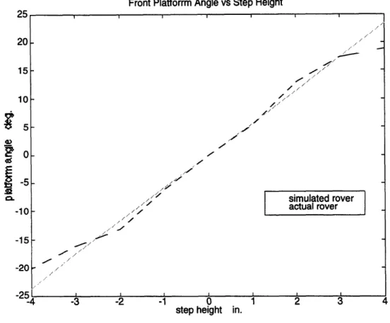
3.7 Front Platform Angle vs Step Height ... 45
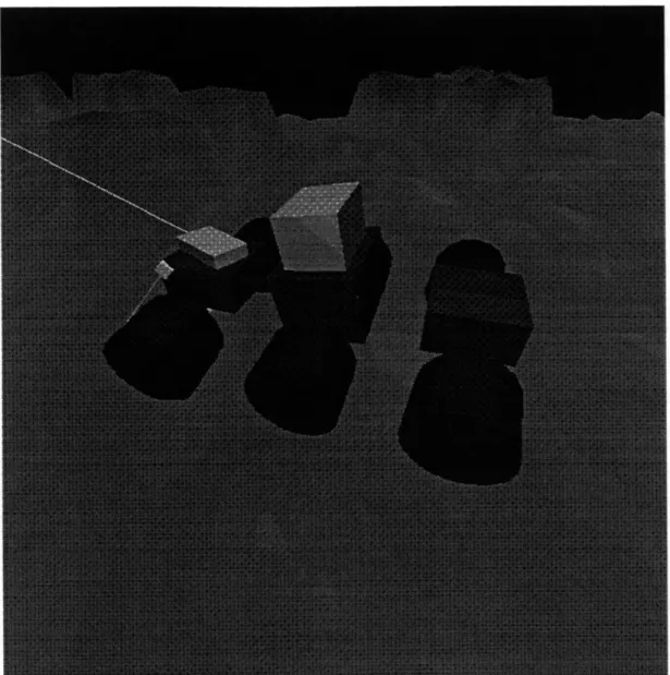
3.8 Three Dimensional Simulation Animation ... 47
3.9 Laser Misdirection ... ... 49
3.10 Proximity Sensor Misdirection ... 50
3.11 Hills and Valleys ... 51
4.1 Rover High Centering Problem ... 56
4.2 Wheel Disturbance Torque ... 57
4.3 Conical Wheels Reduce Dead Zone ... 58
4.4 Different Conical Wheel Types ... 59
4.5 Steering Torque ... ... 60
4.6 Actuated Steering ... ... 61
4.7 Tank Steering ... 62
4.8 Free Pivot Steering ... 64
4.9 A disturbance in Free Pivot Steering ... ... . 66
4.10 Hybrid Steering ... ... 67
4.11 Hybrid Steering Force Disturbance ... 68
4.12 Summary of Steering Systems ... 71
4.14 Current Mechanical Design ... 73
4.15 Photograph of Current Design ... 74
4.16 Wire Routing ... 75
4.17 W orm Gear Train ... 76
4.18 Photograph of Worm Gear Arrangement ... 77
4.19 System Block Diagram Representation ... 80
4.21 Actual and Simulated Step Response ... 81
4.22 Summary of Step Climbing Test ... 87
4.23 Steering System Summary ... 88
5.1 Basic Mechanism Concept ... 92
5.2 Definition of Coordinates ... 93
5.3 Spectrometer Positioning ... 96
5.4 Remote Compliance Center Mechanism ... 99
5.5 Front View of Deployment Mechanism/Spectrometer ... 103
5.6 Side View of Deployment Mechanism/Spectrometer ... 104
5.7 Deployment Mechanism Prototype ... 105
Chapter 1: Introduction
INTRODUCTION
CHAPTER 1
1.1 MOTIVATION
It has been twenty-five years since American astronauts first walked on the moon.
Twelve Americans spent a total of 300 hours on the surface of the moon. Then in 1972,
with the launch of Apollo 17, manned lunar exploration came to a halt.
There is no doubt that one day, in the near future, man will again explore the
surface of our moon, the surface of other planets, and other moons. However, this will
not occur before more is known about these distant places.
Today there is a different outlook on programs such as Apollo. Tight economic
constraints make such large expenditures of money difficult. Increasingly NASA and
other science organizations, are moving toward smaller, less expensive missions. These
smaller missions must be very efficient, providing sizable scientific return per dollar
spent. The use of robotic explorers can be an inexpensive and efficient way to gather
scientific information about our universe.
Robotic space exploration versus manned exploration of space has been debated
since the beginning of the space program. Each route has definite advantages as well as
disadvantages. The tremendous success of robotic probes such as Viking, Voyager, and
Magellan have shown that such missions can provide a wealth of information. However,
robotic exploration has its limitations, robots cannot perform many of the tasks that can
only be accomplished by humans.
The desire to return to the moon and then on to Mars is present. This was
expressed in a speech made by President Bush on July 20, 1989, the twentieth
anniversary of the launch of Apollo 11. President Bush called for the development of a
major space station, the return to the moon for permanent manned presence, and a
manned mission to Mars [13].
To help accomplish these goals, within tight economic constraints, NASA has
proposed the use of smaller, faster and cheaper missions. These missions will gather the
knowledge required for such an ambitions exploration initiative.
The Mars Environmental Survey (MESUR) program is designed to increase our
knowledge of the planet Mars. This program includes a precursor mission called
MESUR Pathfinder. The purpose of the Pathfinder mission is to demonstrate Mars entry
and landing technology as well as the use of a micro-rover for exploration. Following
this will be larger missions to set up 8 to 16 science stations on the surface of Mars.
Chapter 1: Introduction
These stations will study meteorological and seismic activity for two Martian years (approximately four earth years). The effectiveness of these stations will be augmented by the use of a micro-rover. A micro-rover is a small vehicle which will extend the reach of each station by exploring the surrounding area and transporting scientific instruments
[15].
1.2 ROVERS AND MICRO-ROVERS
Rovers are vehicles that can be used to explore the surface of a planet. Rovers have been used by both the United States and the Soviet Union in the exploration of the moon. These rovers have been manned and unmanned.
The United States launched a rover with the Apollo 15, 16, and 17 missions. This lunar rover was a four wheeled vehicle designed to transport two astronauts. These rovers could traverse large distances and it greatly increased the area that could be explored by astronauts.
In 1970 the Soviet Union also landed a roving vehicle on the moon. This rover was an unmanned vehicle used to gather scientific data. It operated for 220 earth days (7 lunar days). The Soviet Union controlled their rover from a station on earth. This
method or robotic control is called tele-operation. This rover was followed by another successful rover mission in 1973.
A planetary rover must be highly mobile to traverse the unknown surface of another planet. The rover must be capable of transporting payload to various locations across the surface. This payload may be in the form of astronauts or scientific
instruments.
The recent miniaturization of electronic and mechanical devices makes the use micro-rovers possible. A micro-rover is a smaller vehicle weighing approximately 20 pounds (10 kg). Because of the micro-rover's small size transportation cost to the planetary surface is greatly reduced. This makes it possible to launch a small army of these vehicles to explore many diverse locations across the surface of a planet. A large number of independent rovers greatly increase the probability of a successful mission.
1.3 MISSION REQUIREMENTS 1.3.1 Goals
A rover would be carried to the surface within a stationary landing craft. This craft, referred to as a lander, will most likely be the communications link between the rover and earth. Various mission scenarios call for rovers to operate tethered to the
Chapter 1: Introduction
lander or as stand alone systems. The rover would receive high level mission commands from the ground crew on earth, while being required to make low level decisions on its own. For instance, the rover would be given a destination from the ground crew, then would be required to reach that destination on its own. Once the rover has arrived at it's destination it would transmit a video image to earth and perform scientific experiments. After this work is complete the rover would shut down for the day and recharge its batteries.
This video image would then be examined by the ground crew. A place of interest in the photograph would be chosen as the next destination. This ground image could be combined with a rover simulation to test the rovers ability to reach this destination. Then this new destination, along with hints on how to get there, could be sent to the rover for the next day's mission.
The current concept calls for a thirty day mission, with the rover traveling 100 yards (100m) per day. Each day the rover will transmit 2 video images [4].
1.3.2 Environments
For a rover to complete its task, it must be capable of surviving in the harsh environment of another planet. The rover will also be subjected to the harsh environments of launch from earth and transport to that planet.
During launch the rover will experience excessive vibrations from the rocket engines as well as static loads from its acceleration into space. Once in space the rover will experience temperature extremes, a vacuum, and intense radiation. When the rover arrives at its destination it must survive the loads experienced as it lands on the surface of the planet (impact loads estimate is 50g).
Once on the Surface of Mars, the rover will be subjected to more temperature extremes. Temperatures vary from -1930F (-1250C) to 710F (220C). Mars's atmosphere
is primarily carbon dioxide and a much lower density as compared to earth's atmosphere. The pressure of the Martian atmosphere is approximately 1% of earth's. Severe winds are common on the Martian surface, winds at the Viking landings sights reached 55 miles per hour (90 kph). These high winds, coupled with the fine Martian soil, make resistance to fine dust a necessity.
The lunar surface is a bit different than the surface of Mars, primarily because the moon lacks an atmosphere. The lunar terrain is much less rocky than the Martian surface but it is covered with a fine dust and many craters of all sizes.
Chapter 1: Introduction 1.4 THESIS SCOPE
This thesis describes work done to advance the development of a planetary rover, called MITy. MITy is designed to explore either the surface of the Moon or Mars.
In chapter two, previous work on the MITy series of rovers is described. Chapter three discusses work done on a three dimensional kinematic simulation used to test and evaluate the performance of the rover design and hazard avoidance ability. Chapter four describes the design and evaluation of the third prototype rover. Then, chapter five discusses the design and development of a mechanism to deploy scientific instruments from the rover. Finally, a summary of the conclusions drawn from this work can be found in chapter six.
Some work described in chapter three and four was conducted with the aid of other rover team members. In section 3.4 the simulation animation software was coded by Kimbal Thurston. Also, modifications to the rover hazard avoidance software
discussed in section 3.5.1 was done in cooperation with Eric Mallefew. Electronic work associated with the construction of MITy-3 was done by Sean Adam. The Author was aided in the mechanical construction of MITy-3. Giang Lam designed and built the conical wheels and instrument box frame and Bill Kaliardos helped in the construction of the steering system. Special thanks goes out to these team members for their
Chapter 2: The MITy Rovers
THE MITY ROVERS
CHAPTER 2
2.1 THE MITY SERIES
The MITy rover series has been developed at the Charles Stark Draper Laboratory in conjunction with the Massachusetts Institute of Technology. Development of the MITy rovers has been undertaken as a student project. This Project began in the fall of 1990 with an initial systems study completed in June 1992 [4]. To date, three prototype rovers have been built: MITy-1, MITy-2, and MITy-3. Development of both MITy-l and MITy-2 has been completed, while construction of MITy-3 continues.
While teleoperation of a rover on the moon is possible, the long communications delay between earth and other planets (up to 40 minutes) makes teleoperation impractical. For this reason the design of the MITy rovers has concentrated on a high degree of autonomy. Each of the three prototype rovers are completely self-contained units carrying with it its own power supply, processor, and sensors.
In order to complete its mission a rover must be capable of finding its way through an unknown environment. To accomplish this task, the rover must be able to sense its environment, detect problem areas, and avoid them. The rover must also know where it is, where it has been, and where it is going at all times. To accomplish this the MITy rovers are equipped with a complete navigation and hazard avoidance sensor package.
2.1.1 Basic MITy structure
Structure
Each rover is based upon an articulated three platform frame. Two wheels extend from the sides of each of the three platforms. Motors within each wheel provide
actuation. Connecting the individual platforms are two flexible steel rods. These flexible rods allow relative motion between the platforms in both pitch and roll rotations, but not yaw. The basic rover structure is illustrated in figure 2.1.
Chapter 2: The MITy Rovers
rover platforms
flex in
flex in roll
-x
4
Il•AIUIC• U ULl I UUD
Figure 2.1: Basic MITy Structure
Since the rover spends most of its time moving forward, the front platform is dedicated to hazard avoidance sensors. The front platform is also home to the video camera as well as the video and data transmitters. Within the center platform is the main processor and power regulation circuitry. Navigation sensors are also primarily located on the center rover platform. The rear platform carries the rover battery power supply as well as the recharging solar array. Space on the rear platform has been reserved for scientific instruments.
Locomotion
As the rover traverses rough terrain the flexible frame of the rover will adapt and conform to the terrain beneath it. This helps redistribute the weight of the rover, and
guarantees good contact between each wheel and the ground. The use of six wheels, as opposed to four, helps ensure sufficient wheel-ground traction. Using six individually powered wheels maximizes the number of wheels in contact with the ground. If one or two wheels would happen to loose traction, for whatever reason, the other wheels will still provide traction. Also, with six individually powered wheels, the system becomes more resilient to a motor failure and therefore much more reliable.
Steering
MITy-1 and MITy-2
Rover steering is accomplished by rotating the front and rear wheel pairs while the middle platform wheels remain fixed. A rover right turn is shown in figure 2.2a. MITy-1 and MITy-2 utilize an Ackerman steering system similar to that used on
Chapter 2: The MITy Rovers
near each wheel's contact point, reducing the torque required to turn them. Wheel steering is actuated by a servo motor located on the front and rear platforms. This steering servo is connected to the wheels by a linkage as shown in figure 2.2b.
servo
rotation
linkage
steering servo
a) Rover Right Turn
Top View b) MITy-1 and MITy-2 Steering Figure 2.2: MITy-1 and MITy-2 Steering
This linkage, along with the servo motor geometry, gives the rovers a fixed minimum turning radius. MITy-1 has a 24" turning radius while MITy-2 has a 19" turning radius.
This turning radius is a limitation that must be accounted for in planning the motion of the vehicle.
Power
Electrical power on a MITy rovers is provided by rechargeable nickel-cadmium batteries. MITy-1 carries a total of 54 watt-hours on board while MITy-2 and MITy-3 each carry 24 watt-hours. MITy-2 is also equipped with a solar panel to restore on board power. The current solar panel charges at a rate of six watts.
Processing
Processing for MITy-1 is provided by a Motorola 68HC11 processor. This is a 2 MHz micro-computer with 32 kbytes of memory.
Chapter 2: The MITy Rovers
MITy-2 and MITy-3 utilize a ZILOG Z-180 micro-processor. This is a more powerful processor then implemented on MITy-1. The Z-180 processor is a 12 MHz processor with 256 kbytes of memory. MITy-3 has a memory expansion to 512 kbytes.
Processor performance is a major concern since the processor is responsible for all aspects of rover operation. Obviously sophisticated sensors and sophisticated hazard avoidance planning place a great demand on the rover's processor. There are also strict size and power restrictions placed on the processor.
Vision
Both MITy-1 and MITy-2 are equipped with on board video cameras. These cameras are used to gain information about the rover's surroundings. Obtaining this picture information would be a primary goal of a planetary rover's mission. Currently the video information is merely transmitted to the ground station and is not used by the rover itself. Work is in progress to utilize this video in navigation and hazard avoidance. For more information on this work see [6].
2.1.2 MITy-1
MITy-1 was a proof-of-concept platform. The intention of this rover was to show that a vehicle could be built that would satisfy the basic mission requirements such as
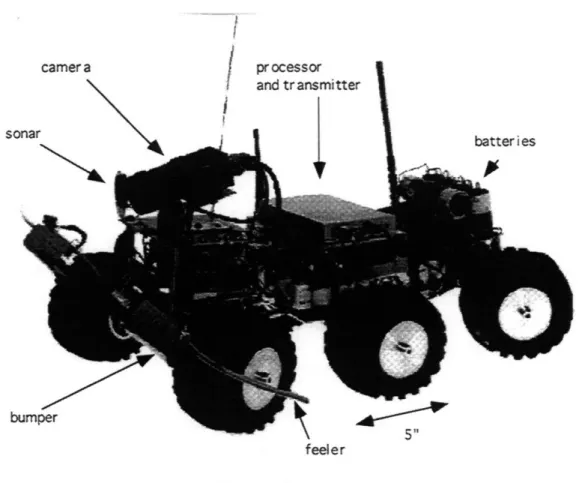
size, weight, cost and vehicle performance. A picture of this rover can be seen in Figure 2.3.
Chapter 2: The MITy Rovers
Figure 2.3: MITy-1 Platform
MITy-1 is the smallest of the three MITy rovers. MITy-1 is 26" long and 13.4" wide weighing approximately 20 lbs. (8.9 kg).
MITy-l's locomotion is provided by six IM-13 globe motors. These motors are accompanied by a spur gear head with a speed reduction ratio of 96:1. After gearing these motor's theoretical stall torque is 327 oz.-in (2.314 N-m). This allows the rover to climb a 3.75" step consistently, approximately 75% wheel height.
Sensors
Sensors implemented on MITy-1 are not realistic sensors for use in a planetary mission. Since MITy-1 was a proof of concept vehicle, sensors were chosen on the basis of cost and simplicity, rather than actual mission performance.
Navigation
MITy-1 uses a drag wheel to measure distance traveled. A drag wheel is an unpowered wheel that is pulled behind a rover platform. An unpowered wheel provides
Chapter 2: The MITy Rovers
better distance information than a powered wheel because it is less susceptible to slip. Drag wheel rotation is measured by an optical encoder from which rover travel distance can be calculated.
A magnetometer is used on MITy-1 to determine vehicle heading. This heading information, coupled with vehicle travel, allows the rover to determine its position relative to where it began.
This method of indirectly determining location is called dead reakoning. In dead reakoning, motion information such as wheel speed and heading are integrated to
estimate vehicle position.
Hazard Avoidance
Since the rover is traveling through an unknown environment it must be capable of detecting hazards and avoiding them.
For this purpose, MITy-l's primary source of information is three sonar sensors. These sonars are mounted on the front of the vehicle and provide distance information on objects in front of the rover. The sonars are sensitive to objects in a 240 beam width. The combination of the three sonars gives MITy- 1 a 60' field of view with slight gaps.
MITy-1 utilizes feelers to detect its local environment. Feelers are rods that extend from the front edges of the MITy-1 platform. If MITy-1 passes an obstacle too closely the feeler will deflect. The amount of deflection determines the distance to that obstacle.
As a last line of defense MITy-1 has bumpers on the front of the vehicle. If the rover runs into an obstacle, the bumper will be depressed, and a switch will be activated. The bumper is placed above the rover's maximum climbing height.
Vehicle Control Software
MITy-1 is capable of autonomous travel through hazardous terrain. If the rover is given a target with respect to its initial position, it will then drive toward that target while reacting to and avoiding obstacles.
MITy-1 has a purely reactive hazard avoidance scheme. This is to say that the rover does not plan ahead, but merely reacts to the situation in which it is placed. Sonar, feeler and bumper information is integrated to determine the best direction for the rover to travel. Decisions are made based on this sensor information and subgoals are placed to help lead the rover to its destination [1].
All decisions are made based on the assumption that the rover is operating in a two dimensional environment. Tilting of the vehicle due to rough terrain or hills and valleys is not considered in the MITy-1 vehicle control algorithm.
Chapter 2: The MITy Rovers 2.1.3 MITy-2
MITy-2 was the next stage in MITy rover development. It was a big step beyond MITy-1 both mechanically and electrically. The primary goal of MITy-2 was to develop a more mission-ready rover. Mechanical structure, sensor package and software all were upgraded. A photograph of MITy-2 can be seen in figure 2.4.
Inclinometers Su Camera N,
/n
Sei
/
nsor Gyro Solar Panel .000 Laser Range Figure 2.4: MITy-2 PlatformThe platform for MITy-2 is very similar to the first prototype rover. MITy-2 is larger than MITy-1 because additional space was required to house added sensors and equipment. M1Ty-2 is 29" long and 18" wide. MITy-2 also utilizes more powerful drive motors than MITy-1 to increase vehicle mobility. MITy-2 uses Micro Mo 2842 DC motors with a planetary gear reduction of 134:1. These motors have a theoretical stall torque of 924 oz-in (6.53 Nm) after gearing. The gear head efficiency is estimated to be 60%. These motors are also equipped with tachometers.
Sensors
The goal of MITy-2 was to implement a more mission ready sensor package while keeping performance high and costs low. The MITy-2 rover also includes redundancy in
Chapter 2: The MITy Rovers
sensors wherever possible to increase reliability. For more information on MITy-1 and MITy-2 sensor systems see [2].
Navigation
For odometery, MITy-2 uses both an unpowered drag wheel and motor
tachometers. The use of two independent systems increases reliability and accuracy. On flat ground the drag wheel provides more accurate distance data. This is because the drag wheel is unpowered and not as susceptible to wheel slip. Conversely, in rough terrain the drag wheel has a tendency to loose contact with the ground surface and the tachometers provide more reliable information.
MITy-2 uses a sun sensor and a gyroscope to ascertain vehicle heading. Both sensors are mounted on the center platform. The gyroscope measures the angular velocity of the vehicle. This information is then integrated to determine angular
displacement. Over time, the gyroscope is susceptible to drift; therefore, it is used as the secondary system. The sun sensor is used to calibrate the gyroscope and is the primary sensor used to determine vehicle heading. The sun sensor uses a fish-eye lens to project light from the sun onto a position sensitive detector. This information, coupled with inclinometer readings, the time of day and geographic location determine vehicle
heading. The sun sensor is used if a strong signal is received, if this signal is weak or lost the gyroscope becomes the primary heading sensor.
The center platform is equipped with inclinometers to determine it's pitch and roll. These inclinometers are used to avoid situations in which the vehicle might tip over. Readings from these inclinometers also allow for three dimensional navigation.
Hazard Avoidance
The primary hazard avoidance sensor on MITy-2 is a laser range finder. This range finder is mounted on the front platform. The range finder utilizes a triangulation method to provide distance information on obstacles from zero to ten feet. This range
finder is mounted to a rotating turn table to give 180* of coverage in front of the vehicle. MITy-2 utilizes two optical proximity sensors on the front platform to detect crevasses and drop-offs. These sensors are pointed downward in front of the vehicle to determine if the surface ahead of the vehicle is traversable.
The front platform is also equipped with accelerometers to determine the pitch and roll of the front platform. This information is needed to ensure the reliability of other sensors located on this platform such as the laser range finder and proximity sensors.
As a last line of defense, MITy-2 is equipped with bump sensor on both the front and rear platforms. These sensors determine if the rover has contacted an obstacle.
Chapter 2: The MITy Rovers Vehicle Control Software
Hazard Avoidance Software
MITy-2 is able to autonomously navigate hazardous terrain in order to reach a target destination. The rover is in contact with a ground station at all times to report information on its progress and provide real time video images.
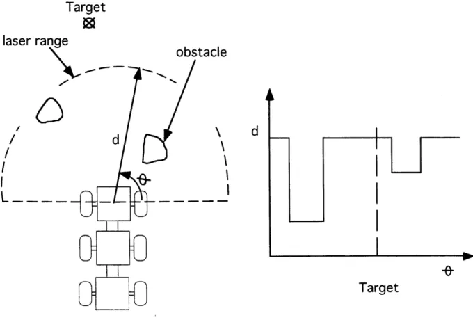
MITy-2 utilizes an effective algorithm which allows the rover to navigate difficult situations while maintaining a maximum degree of vehicle safety. This algorithm, like the MITy-1 control algorithm, is a reactive scheme. The primary sensor information for hazard avoidance comes in the form of distance measurements obtained by the laser range finder. As the range finder sweeps ahead of the vehicle, as in figure 2.5 a), the rover builds a local map of the surrounding terrain. Obstacles in this map appear as shorter distance readings and this is plotted against angular position of the obstacles. A sample map is shown in figure 2.5 b).
Target
laser range
\ obstacled
/ I I,,Target
Chapter 2: The MITy Rovers
Tracking and sensor errors make it is unsafe to pass too closely to an obstacle. For this reason, the obstacle map is adjusted to account for the rover turning radius as well as this passing safety distance to the obstacles, an example of this is seen in figure 2.6 a). This part of the routine balances the trade-off between the travel distance and passing safety while incorporating the vehicle turning radius.
Finally the map is weighted to include the target location and past motion of the rover, as seen in figure 2.6 b). This is to ensure the rover will travel toward the target while avoiding obstacles and will not oscillate left and right on its way.
d
d
Target
Best Steering
Angle
a) map weighted for safety b) map weighted for target location Figure 2.6: Weighted Maps
This planning algorithm also assumes that the rover is operating in a planar environment. Considerations such as hills, valleys, drop-offs, and rock climbing are not
directly considered. Therefore, rover performance is severely degraded when these three dimensional effects are present. Work to alleviate this problem is presented in chapter three of this thesis. Additional information on this work is available in [1].
Ground Station
To aid in the operation of the rover a full ground station has been developed. This ground station enables the user to control the rover via a radio link. The ground station sends commands to the rover and sensor information from the rover is returned to the
Chapter 2: The MITy Rovers
ground station. This is accomplished through a graphical interface on the ground station computer. The ground station allows the user to know exactly what the rover is
"thinking" at all times, so the rover can be monitored or controlled. The user can then teleoperate the rover. With the information gained by the rovers sensors, the user can make decisions for the rover and send commands for the rover to act. With the benefit of a "man-in-the-loop" the rover performance can be greatly enhanced.
This teleoperation can be done on a low or high level. Teleoperation on a low level amounts to sending the rover speed and steering commands. In this situation, the rover's safety mechanisms are still in effect to protect the rover. These safety
mechanisms include the bump sensors and proximity sensors. In a higher level
interaction the rover can be lead to its destination by the placement of subgoals, allowing the rover to decide how to achieve each subgoal. The coding of the ground station was
done by rover team member Matt Ferdette. 2.1.4 Future of MITy Series
With the tremendous success of the first two prototype rovers, work was begun on a third prototype. This rover, MITy-3, is currently under construction and much of this work is included in the fourth chapter of this thesis.
Problems with vehicle mobility are addressed with this third prototype rover. Conical wheels are utilized to increase vehicle mobility and prevent the rover from becoming "high-centered" on obstacles. With the use of conical wheels came the need for a new steering system.
With future prototypes other problems will need to be investigated. The brunt of these problems are associated with the space environment the rover will experience. This includes things such as extreme temperature variation, severe dust, launch vibrations, radiation and the vacuum of space.
2.2 OTHER ROVERS
Micro-rover design is not unique to the MITy series. Development of planetary rovers has been undertaken by teams at the Jet Propulsion Laboratory, Russian Space Agency, Martin Marietta and Sandia National Laboratory. The most advanced planetary rovers have been developed by JPL and the Russian Agency.
2.2.1 JPL's Rocky
The Jet Propulsion Laboratory (JPL) has been working on development of
Chapter 2: The MITy Rovers
Rocky is roughly equal in size to MITy-2. The Rocky series will culminate in 1996 with the flight of a vehicle to Mars in the MESUR/Pathfinder mission. Additional rovers will be launched on later MESUR missions.
JPL's design philosophy has differed from the MITy series in that JPL is creating a space qualified rover. Due to budget constraints this is not yet possible with the MITy program.
Rocky, like the MITy rovers, is a six wheeled vehicle with an articulated frame construction. Rocky's six wheels are individually powered by motors mounted within the wheel. Steering is accomplished by individual steering motors which rotate the four corner wheels. The steering motors pivot these four wheels about the point of contact between the wheel and the ground minimizing tire scrub. JPL also utilizes a discretely articulated flexible frame to increase vehicle mobility. Rocky's frame is hinged to allow the structure to adapt to the ground profile. This arrangement allows Rocky to turn in place and climb vertical steps somewhat higher than its 5.12" (130mm) wheel height. The ground clearance of the rover's main body is slightly higher than this climbing height limit. Although the area beneath the rover is higher than the rover's maximum climbing height, this is still a space where the rover can become high centered and stuck.
For hazard avoidance, Rocky is equipped with two laser range finders and mechanical contact sensors. The range finders flash a strip of light across the ground profile. This signal is detected by a CCD and then distance readings are obtained using triangulation.
JPL uses stereoscopic video images from the lander and the rover to plan Rocky's path. The rover then follows this path sent from the ground crew. The rover does this using on board software and dead reakoning. For navigation the rover uses a sensors such as a gyroscope, inclinometers, and wheel rotation counters. [19]
2.2.2 Russian Rover
The Russian Space Agency is also producing a rover for planetary exploration. The Russian rover, called Marsokhod, is a bit larger than the MITy series rovers. This rover is approximately 4' (1.2m) in length and 3.25' (lm) in width and weighs 175 pounds (75 kg).
Marsokhod also uses an articulated frame with six individually powered drive wheels. The frame connecting the three sections is hinged and these joints are powered so they can be moved or locked in place. This allows the rover to cross small crevasses. Marsokhod is equipped with a radio isotopic thermal generator (RTG) which provides
Chapter 2: The MITy Rovers
rover power. This system produces an abundance of electrical power and thermal energy. The Russian rover utilizes conical wheels as used on MITy-3.
The Russian Space Agency plans a 1996 mission to Mars that will deploy two planetary rovers and a balloon to explore the surface.
Chapter 3: Three Dimensional Rover Simulation
THREE DIMENSIONAL ROVER SIMULATION
CHAPTER 3
3.1 MOTIVATION
3.1.1 Hazard Avoidance Testing
The most challenging aspects of autonomous navigation rise from the lack of detailed information about the environment to be navigated. The problem is further complicated by the uncertain location of the vehicle within that environment. Both of these difficulties are amplified when the problem is considered in three dimensions.
In a two dimensional situation the rover position can be defined by an { x,y } location of the rover along with the rover rotation. Obstacles can be located by determining their { x,y } location with respect to the rover. In a two dimensional
navigation problem an area is either a passable space or an obstacle. If the locations of the rover and the obstacles can be determined, autonomous navigation can be attempted, although this task in itself is by no means trivial.
In a three dimensional scenario the task becomes even more difficult. The rover position must now be defined by at least six variables, three translational and three rotational. In the case of a multi-bodied vehicle, such as the MITy rovers, more variables are required. The definition of an obstacle is also less clear in a three dimensional
representation. Obstacles are no longer simply passable or impassable. Some obstacles may be surmounted while others must be avoided. The definition of an obstacle becomes more complicated including such things as hills and cliffs.
The physical construction of the vehicle is very important in a three dimensional problem. This will determine what obstacles will hinder rover movement and what obstacles the rover can climb. The location of the sensors and actuators can also be adversely affected by three dimensional terrain, therefore their performance may be degraded. For instance as the vehicle climbs a rock the laser range finder will not be in its normal operating position, it may be pointing toward the sky or directly at the ground, and therefore cannot be relied upon.
All of these problems must be considered in the design of a successful hazard avoidance system. Previously, a two dimensional simulation was used to design and evaluate the hazard avoidance system developed for the MITy rovers [1]. Now this work must be built upon by the evaluation of the hazard avoidance routine in more complicated
Chapter 3: Three Dimensional Rover Simulation
and more realistic terrain. To accomplish this, a simulation has been developed to subject the hazard avoidance system to more realistic situations.
3.1.2 Aid to Rover Operations
A three dimensional simulation can be of great use during actual rover operations. At the end of each day the rover will transmit a video image to the ground crew before it
shuts down for the night. This video image will most likely be stereoscopic, therefore, the ground crew can use this information to reconstruct a three dimensional map of the area ahead of the rover. Once this ground profile is constructed it can be used by a rover simulation. This would allow the ground crew to evaluate the rovers likelihood of arriving at its next destination. If problem areas are found the rover can be advised to avoid these areas before it gets into trouble. By identifying problems and avoiding them ahead of time, the rovers performance and reliability will be greatly enhanced. With this help the rover will be less likely to waste time and energy trying to get through areas that are impassable.
This reconstructed map will not be perfectly reliable and the rover will have do much of the work on its own, but the use of multiple simulation runs will increase the certainty of mission success.
3.1.3 Rover Teleoperation Testing
Another use for a three dimensional simulation is in the design and evaluation of a user operating station, or ground station, for the rover.
Work is currently in progress to operate the simulation in conjunction with the existing ground station software. Since the same rover control software is used with the simulation as is used on the actual rover, the ground station can interact with the
simulated rover in the same way it would with the actual rover. The rover control software is really blind to the environment, in other words the control software cannot tell if it is controlling the simulation or the actual rover. This leads to the fact that the rover can be teleoperated in the simulation in the same way as it would be in reality. Now, the simulation can be used to evaluate the user interface and the ground station, i.e. it can be used as a ground station development tool. In this manner the simulation could also be used to train a rover teleoperator.
3.1.4 Sensor Evaluation
Still another use of the simulation would be in the evaluation of proposed sensors. Proposed sensors could be modeled and incorporated into the simulation environment. Once incorporated, the simulated rover could be operated in various terrain and the
Chapter 3: Three Dimensional Rover Simulation
effectiveness of this new sensor could be evaluated. The use of the simulation in this manner would reduce the cost and time required to evaluate a new sensor system. 3.2 SIMULATION STRUCTURE
The evaluation of the hazard avoidance system in a three dimensional environment was the major purpose for which this simulation environment was developed. Therefore, the level of complexity of the simulation was limited by this complexity's contribution to hazard avoidance evaluation. The complete simulation was
separated into two distinct parts: the control system and the environment. The newly developed three dimensional environment has been incorporated with the existing control code to evaluate this control systems performance. Then the results of this merger were used to improve the control system by making it more functional under more realistic conditions.
3.2.1 Kinematic Simulation
In the simulation environment the rover and the ground profile are modeled kinematically. The shape of the ground profile is specified, then the rover is placed on this ground profile. The shape of the rover is completely determined by how it interacts
with, or "rests on", the ground profile. Then the motion of the rover is integrated and its position advanced. No mechanical dynamic effects are considered in the motion of the rover, this ignores things such as bouncing, vibrating or other dynamic effects.
Furthermore, no dynamics are considered in the rover interaction with the ground profile. This neglects thing such as soil conditions, wheel slip and rover sliding. These effects are
considered in a previously developed hi-fidelity simulation that focused on these issues in great detail [3]. The results of this dynamic simulation are used as operational limits for the simulation. For instance, the dynamic simulation placed limits on the maximum slope the rover could climb, and this slope was noted in kinematic simulation development. It was thought that the consideration of dynamic effects would bog down and not be relevant to the goal of the simulation.
3.2.2 Simulation Coordinate Frames
The simulation environment consists of the model of the rover itself as well as the model of the ground profile. The simulation environment is defined by two major
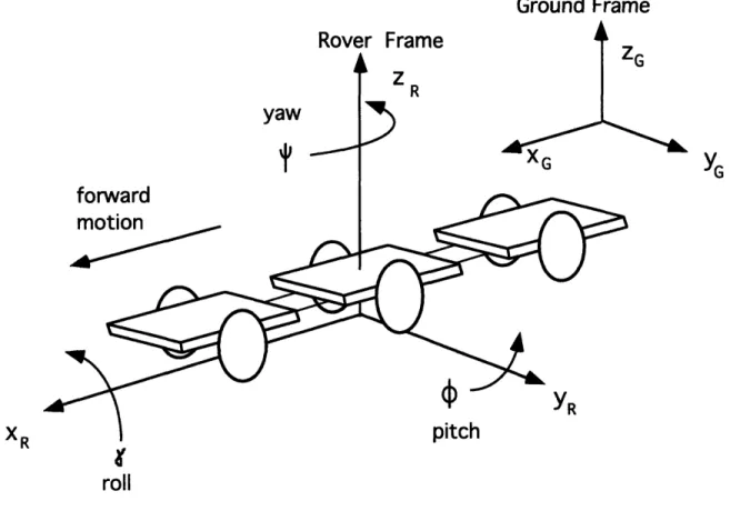
coordinate frames. One coordinate frame is an inertial frame fixed with respect to the ground profile. The second is a moving frame that is fixed with respect to the center platform of the rover. The moving frame is referred to as the rover frame and the fixed
Chapter 3: Three Dimensional Rover Simulation
frame as the ground frame. The origin of this rover frame is placed below the center platform at the midpoint between the contact of the center platform wheels with the ground. The { x } axis of this frame is parallel to the length of the rover with the positive direction forward. The {z} axis is oriented directly upward and the {y} axis is oriented to form a right handed frame. These frames are shown in figure 3.1.
Ground Frame
Rover Frame
yaw
forward
motion
Z
R -Gpitch
roll
Figure 3.1: Simulation Coordinate Frames
A transformation was used throughout the simulation to relate the two frames. The rotations of these two frames with respect to one another is determined by the roll (y), pitch (0), and yaw (xV) of the center platform. The displacement of the origin of the rover frame with respect to the moving frame is defined by the { x,y,z position of the rover.
A vector in the rover frame can be represented in the ground frame by the following transformation:
x
Chapter 3: Three Dimensional Rover Simulation
x cosocosy -sinosinysinW -sinwcosy sin~cosf + cos~sinysinw x rx
y
cos sinJ
+
sinysin cosW
cos y cosf sin40sin4 - sinycos40cosW/ y + ry
Z- G -sin cosy siny cosycos jLXJR rz-G
(equation 3.1) Where { x,y,z } G is a vector in the ground frame, { x,y,z }R is a vector in the rover frame,
{rx,ry,rz G is the displacement of the origin of the rover frame in the ground frame, and 0, y,
v
are the pitch, roll and yaw of the rover frame, respectively. Since the roll and pitch of the vehicle are expected to take on relatively small rotations while the yaw can take on any value, the order of rotation is yaw then roll then pitch. With the singularity in velocity occurring when roll takes on values of nnt/2.3.2.3 Simulation Variables
In the simulated environment the rover is represented by a geometric model. The position of the model is determined by a ten element state vector. The first six elements of this vector contain the { x,y,z } and { 7,,,
}
of the rover frame with respect to the ground frame. The next two elements are the roll and pitch of the front platform with respect to the center platform. Closing out the state vector are the roll and pitch of the rear platform with respect to the center platform. Knowledge of this vector completely determines the position of the rover structure in inertial space.The environment receives control commands for each time step evaluated. The commands are:
1) steering command (servo angle)
2) velocity command (drive motors signal) 3) range finder position command (servo angle)
The environment then integrates the rover heading and velocity to formulate the new position of the center platform. Next the position of the front and rear platforms are determined with respect to this new center platform location. This defines a new state vector for the following time step. Once the state vector has been determined the
orientation of the sensors are calculated and a reading from each sensor is formulated. At the end of this time increment the simulation environment returns to the control code the following variables:
1) rover position
2) gyroscope/sun sensor reading (rover yaw) 3) inclinometer readings (rover roll and pitch)
Chapter 3: Three Dimensional Rover Simulation
5) range finder and proximity sensor distance readings 6) contact sensor (bumpers) status readings
7) drag wheel distance reading
These variables are then used by the control code to produce commands for the next environment time step.
The only dynamics considered by the environment are those that occur on the time scale of the simulation time increment, usually around a tenth of a second. These variables have been found through experimentation to the be servo actuation of the
steering and laser range finder [1]. Both of these systems are modeled as first order responses.
3.3 SIMULATION MODELING
3.3.1 Ground Profile Model
Ground Profile definition is accomplished through the elements of a ground profile matrix. Each element of the matrix represents the height of the ground at that location. By defining the ground profile in this way, there is no distinction drawn between the ground surface and obstacles. An obstacle is simply a higher area of the
ground. The ground profile matrix divides the ground profile into discrete components. This division imposes a resolution onto the ground profile which can be varied to change
the shape of obstacles and to operate the rover on different scales of travel.
Modeling the ground profile has been done in three steps. Initially the ground's large scale variations are produced. This can be done through multiple if-then statements or by a functional definition. On this scale, variation in the ground profile is on a larger scale than the dimensions of the rover. This models things such as hills and valleys.
In the second stage of ground profile definition, obstacles are placed on this underlying ground surface. These obstacles can take the form of sharp hills, cliffs, rocks and craters. Obstacles can be placed randomly on the ground surface or each obstacle location can be specified. To place obstacles randomly onto the ground surface, a desired percent of coverage and nominal obstacle size must be given. Obstacles are allowed to overlap each other, this produces a more realistic looking ground terrain. However, this overlap is only considered once in overall percent of coverage. The height of each obstacle can also be randomly varied or specified. This height can become negative to produce "craters" in the ground profile. For certain situations, a specified obstacle set up may be required. To create a specific obstacle distribution, the {x,y} location as well as the obstacle height must be given.
Chapter 3: Three Dimensional Rover Simulation
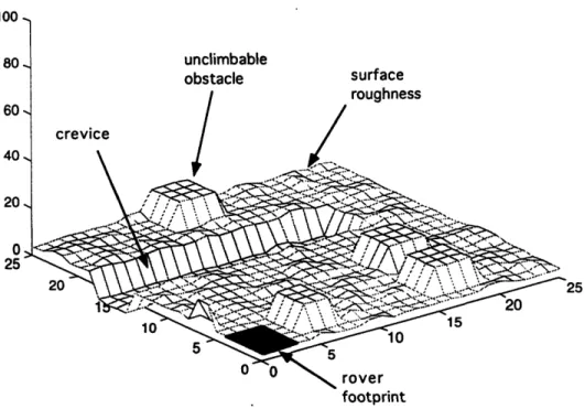
In the last stage of ground profile development, short bumps can be added to produce an overall surface roughness. Once these steps are complete their effects are added to the underlying ground matrix to produce the final ground profile matrix. This produces a very realistic and effective ground profile. An example ground profile can be seen in figure 3.2 .4 A I0 80 60 40 20 0 25 unclimbable obstacle surface roughness crevice footprint
Figure 3.2: Example Ground Profile
Once this matrix has been developed the height of the ground profile is defined continuously over the entire range of the matrix. This is done by interpolating points
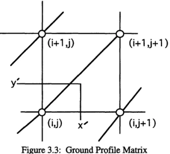
between each element of the matrix. Planes are fit between the elements of the matrix along the forty-five degree line between the elements as seen in the figure 3.3.
Chapter 3: Three Dimensional Rover Simulation
j+1)
.1)
Figure 3.3: Ground Profile Matrix
Once these planes have been defined, the height of any point on the ground can be found by determining on which plane it lies. The relevant grid square for a desired location
{x,y} is found by dividing by the grid resolution. Then {x',y'} is defined for the local grid square as seen in the picture. If x'>y' (as in the figure) with respect to the appropriate grid square, points (i,j), (i,j+1), and (i+1,j+1) are used to define the appropriate local ground plane. If y'>x' the point (i,j+1) is replaced by (i+1,j). These three points define a plane upon which the desired point lies. The corresponding ground height for this {x,y} pair can now be found.
This operation takes the form of a subroutine in the simulation environment. Given an { x,y } point in the ground reference frame a { z }, or height, value for the ground matrix is returned.
Determination of the ground profile in an actual mission would be done by stereo photography. A reconstruction routine has been developed to take such a stereo image and produce a ground matrix identical to the one used by the simulation environment [8]. Defining the ground profile in this way makes the simulation compatible with such photographic techniques. With this capability the control system can by tested on actual terrain data obtained by the rover. This is a powerful tool that allows the ground crew to simulate various runs over an actual ground surface prior to an attempt by the rover. This information can be used to aid the rover along its path.
3.3.2 Rover Platform Model
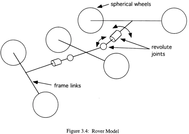
The rover platform is modeled kinematically. No mechanical dynamics are considered. Three rigid members are used to model the body of the rover. These members represent each platform of the rover. Four revolute joints are used to connect
Chapter 3: Three Dimensional Rover Simulation
the members of the model. These four joints allow the front and rear platforms to rotate in pitch and roll with respect to the center platform. The joints are free to rotate, allowing unrestricted motion between platforms. Therefore, the position of the front and rear platforms are completely determined by the underlying ground profile. At the end of each individual member is a sphere. These spheres are used to represent the wheels of the vehicle. It was found that spherical wheels made the rovers reaction to changes in ground profile more realistic than disc wheels. The model of the rover can be seen in the figure 3.4.
. spherical wheels
revolute
joints
links
Figure 3.4: Rover Model Center Platform
Since the rover coordinate frame is attached rigidly to the center platform, this platform is a the major determinate of the state of the vehicle. The { x,y } location of the center platform is calculated from the input commands of the control system. The { z
I
location of this platform is defined by the ground profile given its { x,y } location.
The roll of the center platform is defined by the left and right wheels, each wheel contacts the ground plane. This is accomplished using a numerical technique to solve the kinematics equations that determine the vehicle roll. The Newton-Raphson method is
Chapter 3: Three Dimensional Rover Simulation
used to solve these equations. This method is also used in the determination of the pitch of the center platform and in the determination of the position of the front and rear
platforms. A numerical method was required because of the non-linearity and complexity of the kinematic equations. The method of solution is discussed in the following section which describes its implementation with the front and rear platforms.
With the roll of the center platform determined the remaining variable is the platform pitch. Given only the ground profile and the spherical wheels the pitch of the center platform is unconstrained. To solve this problem two "artificial wheels" are placed in the model. These wheels are located to the front and to the rear of the center platform. These additional wheels are represented by spheres and constrain the pitch of the vehicle. Initially the pitch was defined by making the rover platform parallel to the ground profile. This constraint produced discontinuities in the motion of the center platform because of discontinuities in the slope of the ground profile. These additional wheels are used to smooth this motion and produce realistic values for vehicle pitch. The position of these wheels on the platform, as well as their size, were determined experimentally to emulate the actual vehicle motion.
Originally it was thought the height of the center platform would need to be modified when the rover climbed steep hills. In such a situation the center platform might loose contact with the ground surface. This height correction was calculated using the roll and pitch of the center platform. Correction factors for this purpose were
determined experimentally with the actual rover platform. However this problem is now avoided using the rover model equipped with the "artificial" spherical wheels mentioned above.
Front and Rear Platforms
Accurate modeling of the front and rear platform position was the greatest challenge in the creation of an accurate rover model. Once the location of the center platform is calculated, the front and rear platforms are considered individually. Each platform is positioned such that both spherical wheels touch the ground profile at one point each.
Positioning the front and rear platforms is accomplished by solving two
kinematic equations in two unknowns. The unknowns are the platform roll and platform pitch with respect to the center platform. The first step in setting up the kinematic equations is to define the ground plane beneath each wheel. This ground profile is represented by the equation of a plane under each wheel, and must be defined with respect to the rover coordinate frame. Once these ground plane equations are found the
Chapter 3: Three Dimensional Rover Simulation
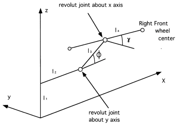
kinematics equations can be set up. The equations are given bellow (equation 3.2) for the location of the front right wheel in the rover frame as seen in figure 3.5
revolut joint about x axis
nt
eel
enter
aDout
y axis
Figure 3.5: Front Platform Kinematic in Rover Frame
X 12
y=1
z- front
[
(equation 3.2)
wheel
where 0 and y represent the pitch and roll of the front platform with respect to the center platform, respectively. These equations represent the position of the center of each wheel in the rover coordinate frame. This point must be one wheel radius distance from the
ground profile. To find the distance between the center of the wheel and the underlying ground profiles equation 3.3 is used:
R lax + byo + cz, +dl
Chapter 3: Three Dimensional Rover Simulation
Where a,b,c and d are the coefficients for the equation of the ground plane, R is the radius of the wheel and { xo,o,zo} are the coordinates of the wheel center (as given in equation 3.2). Specifying the distance between the ground and the wheel center in effect produces a spherical wheel. This wheel radius defines a solution to the equation.
There exists more than one mathematical solution to these equations. For instance both wheels could be beneath the surface or one above and one below and so on. These problems are solved by initially guessing the position of the wheels above the ground profile. Therefore the numerical routine approaches a solution from above. This is, in effect, "dropping" the wheels onto the ground profile.
A very similar method is used for the rear platform as well as the pitch and roll of the center platform. The only changes would be in the geometric position and sizes of the linkage members.
3.3.3 Hazard Avoidance Sensors Laser Range Finder
The primary source of information for the control systems path planner is the laser range finder. The range finder is modeled as a one dimensional beam of light. The range finder is physically located on the front platform and is situated on a rotating base. On the real rover this laser base is moved, in yaw, by a servo motor actuator. The response of the servo motor to a command signal is modeled as a first order response. This response is given by equation 3.4.
fIactual -V=actual + Ncommand
(equation 3.4)
Where Vactual is the actual servo angle, command is the commanded servo angle, and a is
the range finder servo time constant.
Once the range finder angle has been determined, a new coordinate system is placed on the rover. This coordinate system models the position of the range finder. The origin of the coordinate frame is the pivot point of the range finder turn table. The { x axis of this new frame is pointed along the direction of the laser. The transformation between this range finder coordinate frame and the rover coordinate frame is described by the pitch and roll of the front platform and the yaw angle (servo angle) of the range finder.
Due to the piece wise definition of the ground profile an analytic solution to find the laser intersection with the ground profile proved cumbersome. So to produce a range
Chapter 3: Three Dimensional Rover Simulation
finder distance reading, a vector is stepped out along the{x} axis of the range finder coordinate frame at a specified increment. This increment represents the resolution of the actual range finder. The range finder laser beam is then described by a constant
multiplied by the { x } axis unit vector in the range finder frame. This beam is a vector that is transformed into the rover frame and then into the ground frame. Once the laser beam direction is known in the ground frame it is checked to see if it has intersected the ground profile. If there is no intersection the laser beam is steeped out one more
increment until an intersection is found or the sensor's maximum range is reached. If there is an intersection the distance to this intersection represents the range finder reading. One range finder distance is returned to the control system for each time step.
Proximity Sensors
The proximity sensors on MITy-2 are close range optical sensors. These sensors are positioned on the front platform and are tilted downward ahead of the vehicle. Detecting obstacles, such as sharp drop offs, are the purpose of these sensors. A single sensor is located on either side of the front platform. These sensors can also be angled so that their beam passes in front of the front wheels. In this configuration they can also be used to detect unclimbable obstacles that are very close and the laser range finder has missed (similar in function to bumper sensors).
The proximity sensors are modeled in the same fashion as the laser range finder. A line representing the optical beam is found in the ground coordinate frame. Then successive steps are taken along this line until an intersection with the ground is found or the sensor maximum range is reached.
The sensors have a range of roughly twelve inches and resolution of a tenth of an inch. Both range and resolution are represented in the simulation.
Contact Sensors
bumpers
Contact sensors on the MITy rovers are in the form of bumpers. There is a bumper on the front and rear of the vehicle. These bumpers are the rovers last line of defense for obstacle avoidance.
Modeling of the bump sensors is similar to the other hazard avoidance sensors. A line is found that represents the physical orientation of the bumper. This line is first located in the rover frame and then transferred to the ground frame. Once a