PFC/JA-89-10
Design and R&D for the 22 T Central Solenoid for CIT
R.J. Thome, R.D. Pillsbury, Jr., E.S. Bobrov, R. Vieira, J. Feng
April 1989
Plasma Fusion Center
Massachusetts Institute of Technology
DESIGN AND R&D FOR THE 22 T CENTRAL SOLENOID FOR CIT R. J. Thome, R. D. Pillsbury, Jr., E. S. Bobrov, J. Feng, R. Vieira
Plasma Fusion Center, Massachusetts Institute of Technology Abstract
The poloidal field coil system in a tokamak provides the equilibrium, control and shaping fields for the plasma as well as the flux change which induces plasma current and ohmic heating. In CIT all the main coils will play an active part in all these functions. The PF system consists of 16 coaxial coils which will be external to the TF coils and located symmetrically in pairs with respect to the midplane of the machine. Six of the 16 coils comprise the central solenoid assembly.
The OH solenoid will have a bore diameter of 0.68 m, an OD of 1.4 m, a height of about 4.0 m, and a central field of almost 22 T. Geometric restrictions are such that an aggressive structural concept for the conductor is required; hence, the coil will consist of a stack of explosively bonded copper/steel plates. Each plate is machined by a water-jet cutting process. This paper presents features of the design and selected results from an R&D program which is underway.
OH Coil Configuration
The central solenoid will consist of 3 independently excited coil pairs as shown in Figure 1. Of the three coils, the one at the midplane is the most highly loaded and reaches the highest temperature during a pulse. Its temperature rise is determined to a large extent by the fraction of copper in its cross section. The maximum winding stresses averaged over a winding module are determined primarily by the radial geometric constraints imposed by the system and the required flux swing. The worst-case stress in the steel depends largely on the fraction of steel which can be allowed in the winding after allowances for copper, insulation, and cooling passages, as well as local geometric details.
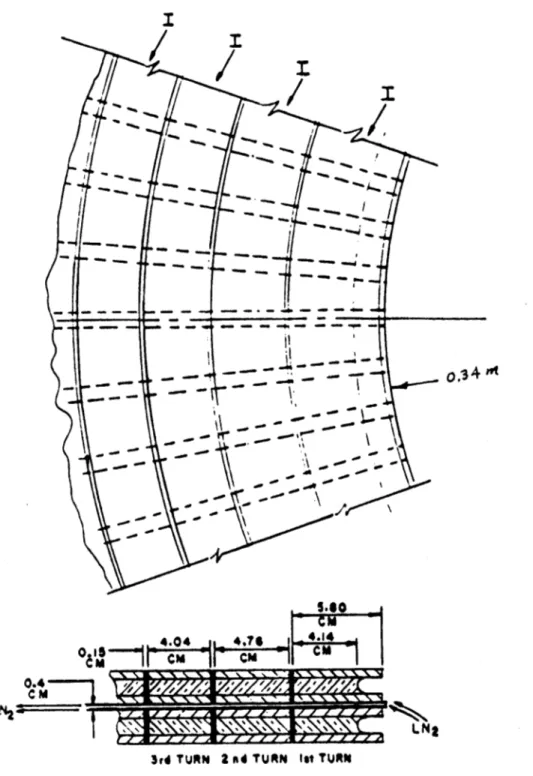
In a typical design with a uniform turn width (current density) distribution with radius, the hoop stress at the worst point averaged over the axial direction (copper and steel) would be about 73 ksi. The fatigue tests to date on laminate show that this level is too high to achieve a projected full power lifetime of 30,000 pulses. The latter is based on a design criterion factor of 5 times the desired number of OH pulses, that is, 6,000. As a result, design features are being implemented to reduce the operating stresses. In particular, a nonuniform turn width distribution is being employed and the fraction of steel available for structure on the first turn is being increased as shown in Figure 2. The result is that the hoop stress at the worst point averaged over the axial direction (copper and steel) has been reduced to 62,000 psi. This implies an improvement in fatigue lifetime approaching 30,000 pulses, but must be confirmed in the R&D program. The corresponding Tresca stress in the steel at the worst point in this "extended" steel or reinforced design is 92,000 psi. This is about 61% of the 718 steel yield stress.
The flux swing bias in the PF system is selected so as to achieve the same Tresca stress level in the steel at the worst turn in the OH at the two times during a machine cycle at which its load peaks. The temperatures at these times are about 100 K and 240 K,
respectively, and the maximum temperature for the coil is 300 K at the end of the pulse. Analyses have shown that the coils heat up essentially adiabatically so LN2 cooling during the pulse would not be effective.
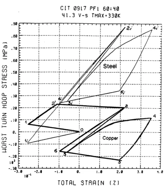
Figure 3 shows the worst-turn hoop stress in the copper and in the steel versus total strain (mechanical and thermal) for the first and subsequent cycles. Both the copper and steel are in a state of zero stress at room temperature at point 0. When the system is cooled down to 80 K, the copper goes into tension at point 1 and the steel goes into compression at point li. When the pulse moves toward the first load peak in the solenoid and the temperature simultaneously increases to about 100 K, the steel loads elastically from 1i to 2i and the copper loads from 1 to 2' where it yields and proceeds to 2. Next, the system unloads and reloads toward the second load peak where the temperature is about 240 K. During this interval, the steel passes from 2i to 3i to 4i, and the copper from 2 to 3 to 4. The system then unloads but still increases in temperature to a level of 330 K. The corresponding path for the steel is from 4i to 5i and for the copper, from 4 to 5. Finally, the system is cooled down to 80 K which brings the steel to 6i and the copper to 6. The paths which have been described occur only on the first cooldown and cycle. On subsequent cycles, the steel traverses the path 6i-2i-3i-4i-5i-6i and the copper follows 6-2-3-4-5-6. The derived paths are based on total (i.e. - mechanical and thermal) strain compatibility for the copper and steel at all points.
It is useful to subtract the thermal portion of the strain from the previous figure. The result is shown in Figure 4 which has cycle points marked to correspond to the previous figure. This plot clearly shows that the steel operates in an elastic range for all cycles and that the copper yields on the first cycle, but operates elastically on subsequent cycles with a strain range of about 0.35%.
R&D Status
Programs are underway in the areas of explosive bonding of the steel/copper/steel laminate and the subsequent water jet cutting of the bonded plates into the spirals to form individual pancakes. Three vendors have been used to produce bonded plates from 15 x 15 inches in area to 60 x 60 inches. The bonded plates have provided materials for mechanical and electrical test purposes, data on the requirements for an acceptable bond, and preliminary data on the bonding parameters necessary. The bonding effort is now entering the second stage which involves contracts with multiple vendors for a total of 16 full scale plates.
Water jet cutting has progressed to laminates at close to full scale. Cutting rates and surface finish conditions are promising. Issues presently being resolved involve cut width tolerances and removal of sharp corners.
Our laminate mechanical testing program has focused on determining the fatigue life in load controlled tests for materials in the "as received" condition. A total of 57 samples have been tested with the load parallel to the laminate under conditions of R = 0 (ie "tension-tension"). Tests have covered a range of copper to steel ratios from 60/40 to 50/50, since this is expected to bracket the requirements for the CIT solenoid.
Preliminary results indicate that:
a) The interface ripple amplitude between the copper and steel, which results from the explosive bonding process, should be held below a maximum value of about 0.005 in. This will limit the degrading effects of shear bands and microcracks in the steel. b) The orientation of the load relative to the ripple direction improves lifetime by about
a factor of 3 if the load is parallel to the interface ripple rather than perpendicular to it.
c) At a given average stress level across the laminate section, the lifetime at 80 K is about 4 times the lifetime at 300 K.
d) Lifetime is a strong function of average stress and also improves as the copper/steel ratio decreases.
The impact of the load orientation angle, alpha, is clearly seen in Figure 5 which is a 3D plot of the room temperature data for cycles to failure vs stress level with load orientation angle as the third axis. Lifetime increases with decreasing average stress and with increasing alpha, that is, with the load applied parallel to the bond interface waves. In the solenoid this would occur naturally if the plates were bonded with a center initiation for the explosion in the bonding process. If center initiation is not practical, it will still be possible to orient the plate during the cutting process such that the interface wave direction is most favorable in the vicinity of the most highly stressed points (e.g., at the inside joint or turn-to-turn transition).
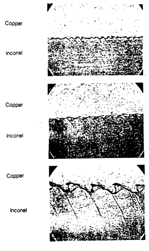
The impact of interface ripple amplitude is illustrated in the photomicrographs in Figure 6 which are all to the same scale. Each photo shows the ripple at a copper/steel interface, but the samples are from different plates which, because of variations in the explosion parameters, have substantially different ripple amplitudes (defined as peak to trough distance). In all cases the lines in the steel which angle down and to the right are shear bands, that is, areas of severe plastic deformation caused by the bonding process. The length and severity of these deformations increase as ripple amplitude increases. At large amplitude, the bands also involve microcracks. This was studied at length to determine an upper limit on wave amplitude, below which microcracks did not occur.
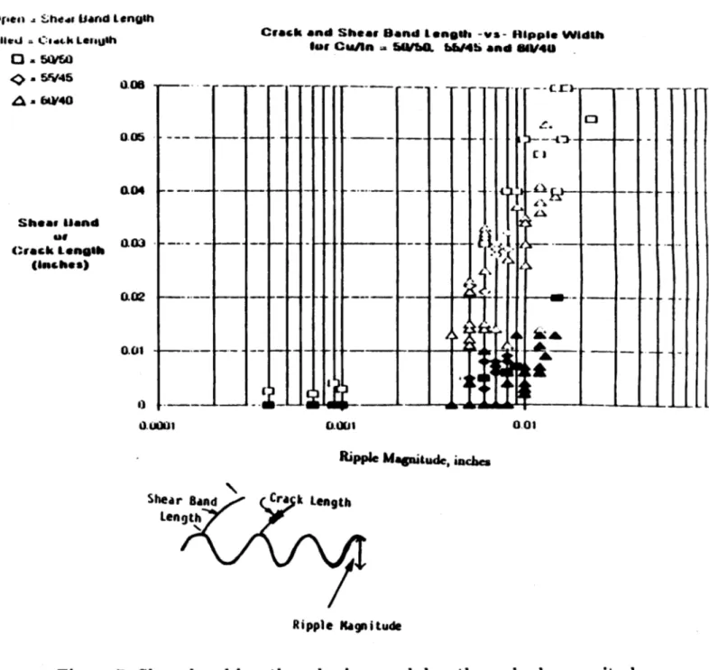
The interface character for samples over the entire range of copper/steel ratios tested was examined at 500 X and the plot shown in Figure 7 was constructed. The open points represent the measured length of the shear bands in the samples plotted vs the ripple magnitude. Results indicate that the shear bands decrease in length as ripple amplitude decreases, but that the shear bands were present in the steel in all cases.
If the ripple amplitude is large, the shear bands are severe and microcracks develop. The filled points in the plot represent the measured length of microcracks in the samples as a function of the ripple amplitude. The plot shows that the microcracks were not present provided the ripple amplitude was less than about 0.004 inches. The implication is that microcracks can be prevented if the bonding parameters are adjusted such that the ripple amplitude is less than this value. This amplitude will, therefore, be considered as the basis for part of a bond specification in the next round of explosion bonding.
Conclusion
A design and R&D activity is underway for a large bore, liquid nitrogen cooled central
solenoid for CIT. The system constraints require the use of an aggressive structural design involving a cu/steel laminate as conductor. Results from the R&D program imply that the explosive bonding and water jet cutting of the required plates are feasible and that fatigue characteristics are acceptable. Tasks involving development of suitable electrical and mechanical joints have been initiated and will be reported at a later date.
PF 3 (UPPER) (UPPER) PFI PF2 LOWER) PF 3 ( LOWER) PF3 STRUCTURE - TIE ROD - COMPRESSION COLUMN
I
D
Figure 15.6o
03 0
0.4
3, TURN 2 nad TURN lot TURN
Figure 2 The first turn has additional steel and the second turn is wider than turns 3 - 8
CIT 0917 PFI 60:40 41.3 V-s TMAX-330K .90 .80 .79 .60 .50 .40 . 30 -.20 .10 0. -. 10 -. 20 -. 30 -3. 3.I
Figure 3 Worst-turn hoop stress vs total strain (mechanical plus thermal) for copper and steel
for first and subsequent cycles
LLJ CO CCD
z
CC CI-, 0 7 -L.8 0. 1.0 2.6TOTRL
STRR[N (M) ' ~ I I I Tr T - 4' ... ... ..- ... ... ... -7 --- -- ---- --- ---- - - --- --- ---.. ... .. * Cpper~.... ...
...
-.---
--- --- ---..--- -.--
- -.--
- -
.
- ---. .. . ... . . . . | . . .... . .. ....-6 -2.8CIT 091.7 F1 60:4~0
41.3
v-s
TMAX-330K
19 1 .90 .70 .60 C!) Cf) .5 LLU .30 a-.30 0. - 10 . .20 -. 30 5.6Figure 4 PF1 worst-turn hoop stress vs mechanical strain for copper and steel for the
first and subsequent cycles.
. . . .. . . . . . . . . . . .. . . . .. , .. . . . . . .. ... *S /ta.e.,:: --- --- . . . .... ... . . .... ...--- .... .. ...---... .... Copper .6 1.0 2.6 3.0 4.0
MECH-RNICRL ST!9RIN (Z)
6.0106
All Samples at Room Temperature
I C), 104 --
0---
80
60
103 -...40
65
-0
20
75
80
0Alpha
Stress (ksi)
Figure 5 Cycles to failure vs stress and load orientation angle for laminate with a Cu/steel
ratio of 1.5
U-0
4-Copper
Inconel Copper.- - InConel---Copper. . *.*: ... Inconel 4.4W .Figure 6 Variation in copper-steel interface characteristics among samples with interface ripple amplitudes of 0.07, 0.15 and 0.40 mm.
a:.rsen .- :.heou band Lengsh
Vlied C:odck LessUlh Crack and Shear Band tength -vs- Hippie Width
fair Cua/Sn - 50/t&. hb/4h and 6/410
0 - 50/w . 5f45 A a 6iW40 Shear Hand Crack .ength (inches) 0.08 -r -- r -r-rr 0.05 004 a03 0.01 4--I- -- " -4 -++-[4-- i-0 f--0.0001 0.O01 - - - . -- Cr)---- I -2 0.01 --- I
-7
n
Ripple Magnitude, inches
Shear Band Cra k Length
Length
Ripple Magnitude
Figure 7 Shear band length and microcrack length vs ripple magnitude.
---i---L-L.L
- -- LO 11111 A -- ---- --M---i-- -V-I -t t r - -- M-f


