deForm: An interactive malleable surface for
capturing 2.5D arbitrary objects, tools and touch
The MIT Faculty has made this article openly available. Please share
how this access benefits you. Your story matters.
Citation
Sean Follmer, Micah Johnson, Edward Adelson, and Hiroshi Ishii.
2011. deForm: an interactive malleable surface for capturing 2.5D
arbitrary objects, tools and touch. In Proceedings of the 24th annual
ACM symposium on User interface software and technology (UIST
'11). ACM, New York, NY, USA, 527-536
As Published
http://dx.doi.org/10.1145/2047196.2047265
Publisher
Association for Computing Machinery (ACM)
Version
Author's final manuscript
Citable link
http://hdl.handle.net/1721.1/79860
Terms of Use
Creative Commons Attribution-Noncommercial-Share Alike 3.0
Detailed Terms
http://creativecommons.org/licenses/by-nc-sa/3.0/
deForm: An Interactive Malleable Surface For
Capturing 2.5D Arbitrary Objects, Tools and Touch
Sean Follmer
1, Micah K. Johnson
2, Edward H. Adelson
2, Hiroshi Ishii
11
MIT Media Lab
Cambridge, MA
{sfollmer, ishii}@media.mit.edu
2MIT CSAIL
Cambridge, MA
{kimo, adelson}@csail.mit.edu
ABSTRACTWe introduce a novel input device, deForm, that supports 2.5D touch gestures, tangible tools, and arbitrary objects through real-time structured light scanning of a malleable surface of interaction. deForm captures high-resolution surface deformations and 2D grey-scale textures of a gel surface through a three-phase structured light 3D scanner. This technique can be combined with IR projection to al-low for invisible capture, providing the opportunity for co-located visual feedback on the deformable surface. We de-scribe methods for tracking fingers, whole hand gestures, and arbitrary tangible tools. We outline a method for physi-cally encoding fiducial marker information in the height map of tangible tools. In addition, we describe a novel method for distinguishing between human touch and tangi-ble tools, through capacitive sensing on top of the input surface. Finally we motivate our device through a number of sample applications.
ACM Classification: H5.2 [Information interfaces and presentation]: User Interfaces.- Graphical user interfaces.
General terms: Design, Human Factors.
Keywords: 2.5D input device, Malleable Surface,
Deform-able Interfaces, Sculpting Interfaces.
INTRODUCTION
When interacting with highly malleable and deformable physical surfaces and forms in the real world, such as clay, there are diverse possibilities for input. Sculptors use their entire hands to shape and deform, not just their fingertips, providing nuanced control. Sculptors also use a variety of tools with complex shapes to displace clay or to add tex-ture. These tools afford higher precision and more variety than hands alone. But in addition to sculpting tools, any arbitrary object can be used to deform clay.
When sculptors deform clay, they also feel the feedback of the clay pressing back. This enables sculptors to accurately gauge how much material they are removing or the manner
in which they are shaping the medium. By combining these various inputs, sculptors transform blocks of clay into ex-pressive and meaningful forms.
What if we could combine the expressivity of clay with the benefits of digital interaction to allow for input from hands, tools and arbitrary objects with co-located visual feedback? Users could use their fingers and hands to pinch and de-press the form. They could use a physical sculpting tool to add fine detail, find a physical object to imprint a complex texture into the form. Users could also feel the defor-mations while producing them, because of the immediate feedback from an elastic input surface.
To capture complex interactions of hands, tools and arbi-trary objects, we propose using high resolution real-time 3D scanning. Dense real-time 2.5D/3D input has only re-cently become available and affordable, bringing the flexi-bility to use arbitrary objects as input. Some camera-based solutions often focus on mid-air interaction, and lack the physical feedback of real-world malleable surfaces. Other researchers have shown that passive haptic feedback can enhance precise, expressive input [16,27,33].
Our solution combines a passive deformable surface with real-time 2.5D capture to support a wide variety of input. Instead of directly tracking tools, objects, or hands, our system indirectly senses them through deformations of a highly pliable surface. This approach provides passive hap-tic feedback, and makes clear to the user where the surface of interaction begins and when objects are being scanned. Any object can be used as input, and its shape and 2D gray
Permission to make digital or hard copies of all or part of this work for personal or classroom use is granted without fee provided that copies are not made or distributed for profit or commercial advantage and that copies bear this notice and the full citation on the first page. To copy otherwise, to republish, to post on servers or to redistribute to lists, requires prior specific permission and/or a fee.
UIST’11, October 16–19, 2011, Santa Barbara, CA, USA.
Copyright © 2011 ACM 978-1-4503-0716-1/11/10... $10.00.
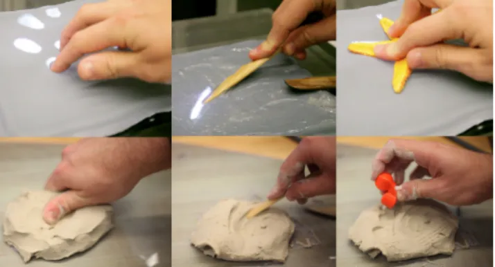
Figure 1. Above: Using hands, tools and arbitrary objects to input with deForm. Below: Using hands, tools and arbi-trary objects to deform clay.
scale texture, or albedo, are captured as it deforms the sur-face of the device. A high-resolution 2.5D capture system allows for increased complexity, overcoming the limita-tions of low-resolution generic deformalimita-tions in order to achieve the desired clay-like sculpting.
We introduce deForm, a real-time 2.5D surface interface that uses infrared (IR) structured light scanning and pro-jected visual feedback. We also detail our solution for tracking arbitrary and tagged tangible tools, touch and hand gestures. We then describe our method for discerning hu-man touch from contact with tangible tools. A number of sample applications highlight the flexibility of input pro-vided by our system; emulating a six-degree of freedom mouse, a sculpting application that uses real sculpting tools, and an application for remixing objects. A discussion of limitations and future work follows.
RELATED WORK
In this section we summarize 3D input and its limitations. We then describe how related work has sought to bring 3D input to 2D surface input.
3D Input
Advances in Stereo Vision and structured light scanning have made 2.5D real-time video capture a possibility. Most recently the Microsoft Kinect, made by Primesense, uses structured lighting to capture real-time, 30hz, 2.5D geome-try at a 640x480 resolution, but is tuned for room scale interactions with a wide angle lens [1]. Custom structured lighting systems have been shown to capture realistic ge-ometry at very high frame rates, by projecting fixed or time sequenced patterns onto objects [40].
One disadvantage of using 3D capture of points or video for input is that it does not provide physical feedback. In addition, these systems provide no physical mechanism to highlight to the user which information is being captured; there is only, in some cases, on-screen feedback. The work
of haptic interfaces such as The Phantom, have explored adding mechanical actuators to 3D input to provide tactile feedback [19]. But these systems only allow for single point interactions and contain many moving parts.
One successful approach has been to combine materials that can provide unactuated, passive haptic feedback with 3D sensing. Illuminating Clay used a laser scanner to scan the front of a clay surface at 1 Hz and projected feedback directly onto the clay [23]. However, the user’s hands inter-fered with scanning, as a result of the camera’s location above the surface. Passive foam blocks tracked with a vi-con system and tracked fingers and tools have been used to enable 3D sculpting [26]. However, this system required augmenting hands and tools with markers, and only provid-ed a simulation of deformations, as opposprovid-ed to capturing true deformations in the surface. We hope to expand on this work by adding real-time 2.5D scanning to a passive malle-able surface to capture real deformations with any object.
Extending Surface Input to 2.5D
There has been a wealth of research on 2D surface interac-tion [5]. Recently many researchers have explored adding more dimensionality to surface input through both above the surface interactions and into the surface interactions. Visual Touchpad used stereovision to enable above the surface 2.5D interaction [18]. More recent work has har-nessed depth-sensing cameras to facilitate above the sur-face interaction [6,10]. Although these systems allow for much larger areas of interaction, they lose some of the ad-vantages of tabletop surface systems, such as passive haptic feedback, and co-located input and output.
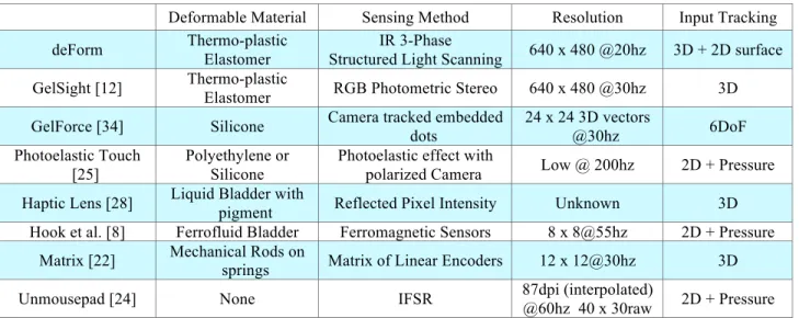
More closely related to our work, into the surface 2.5D interaction allows users to press hands and objects against or into the surface to capture more dimensionality, see table 1 for a comparison of the most relevant systems. Some of these systems measure pressure through force sensitive
Figure 2. Left to Right, Above, Hand deforming gel surface, 3D view and depth map. Below, starfish toy, 3D reconstruction and depth map.
resistors [24], or mechanical deformations [22]. Other sys-tems employ magnetic sensors and deformable magnetic material [8,11,31].
Another approach is to allow the surface to be deformable and to measure its deformation with a camera. Our system takes this approach, and as such we closely review other systems in this domain. One approach uses a deformable projection screen made of lycra fabric or latex rubber, which stretches when force is applied to it, either tracked by reflected pixel intensity [3] or by tracking dots on the surface[35].
A number of these 2.5D surfaces have used a deformable liquid bag or gel as their basis. These systems can more clearly resolve concave shapes. This occurs because the gel or liquid applies a stronger force back on the surface to fill in concavities.
One category of gel/liquid based 2.5D systems provide pressure-sensitive input through pixel intensity from a camera mounted below the surface. Pigment dispersed in a liquid contained in a bag reflects more light the deeper an object is pressed [28,30]. The liquid-based approach does not provide for high-resolution 3D scans, cannot allow 2D texture information to be captured, and has physical stabil-ity issues due to fluid movement [7].
Gel-based input systems provide a stable deformable sur-face to interact with. Photoelastic Touch, utilizes polarizers to measure the photoelastic effect of deformations into gel surfaces [25]. This provides a fairly low resolution spatial pressure map, limited to finger scale detail. Furthermore, spatial resolution decreases dramatically with increased input force. Smith et al. showed that a deformable gel on top of an FTIR multitouch system can provide pressure information [29].
A more sophisticated marker-based system, Gelforce uses two grids of visible markers vertically offset in the gel and a single camera to derive true 3D force vectors applied to the gel [34]. This system has many benefits, but its resolu-tion is limited by the size of the dots. These optical dots also obscure the surface and preclude 2D texture recon-struction.
GelSight uses a gel with a painted surface and a photomet-ric stereo system to capture 2.5D surface normals [12]. This system is limited to only accurately reconstructing shallow surfaces because photometric stereo does not capture pre-cise depth disparities [20]. In addition Gelsight is highly dependent on surface color, requiring a thick layer of paint. Furthermore it cannot capture independent 2D texture of an object. Our system uses structured lighting to triangulate surface geometry and is less sensitive to depth discontinui-ties.
Our system provides many benefits beyond existing work in into the surface 2.5D input. It allows for high-resolution dense surface reconstruction, 2D texture capture in the IR spectrum, to allow for simultaneous 2D visible light feed-back at interactive rates. This paper also introduces depth-based fiducials, and a method for discerning touch from passive tools.
Deformable Material Sensing Method Resolution Input Tracking deForm Thermo-plastic
Elastomer
IR 3-Phase
Structured Light Scanning 640 x 480 @20hz 3D + 2D surface GelSight [12] Thermo-plastic
Elastomer RGB Photometric Stereo 640 x 480 @30hz 3D GelForce [34] Silicone Camera tracked embedded
dots 24 x 24 3D vectors @30hz 6DoF Photoelastic Touch [25] Polyethylene or Silicone
Photoelastic effect with
polarized Camera Low @ 200hz 2D + Pressure Haptic Lens [28] Liquid Bladder with
pigment Reflected Pixel Intensity Unknown 3D Hook et al. [8] Ferrofluid Bladder Ferromagnetic Sensors 8 x 8@55hz 2D + Pressure
Matrix [22] Mechanical Rods on
springs Matrix of Linear Encoders 12 x 12@30hz 3D Unmousepad [24] None IFSR 87dpi (interpolated)
@60hz 40 x 30raw 2D + Pressure
Figure 3. The thermoplastic Elastomer deforms when force is applied but returns to normal state quickly, as seen in the middle image.
Table 1. A comparison of some existing malleable input devices. DeForm also supports tools, touch, collocated projection and 2D texture capture. Gelforce and Photoelastic Touch also have visual feedback.
SYSTEM DESCRIPTION
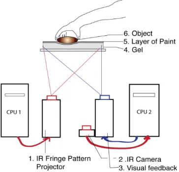
Our system for 2.5D input consists of two parts: a passive, deformable gel surface coated with a thin layer of paint, and a camera projector system for real-time 3D scanning of the paint surface from below.
We use a 1 inch thick gel surface, which is cut into a square measuring 8 by 8 inches. The gel is deformable, but very elastic, and returns to its normal state after the object is
removed. The gel is optically transparent and the surface is painted with a gray paint to capture only the geometry of the surface of the gel as opposed to objects above the gel. The painted surface can also be used as a projection screen. The gel sits on a piece of clear glass through which the pattern is projected onto the gel, see figure 4.
deForm uses a structured light system to capture defor-mations in the surface of the gel in 3D. Our system imple-ments the Three-Phase structured light scanning techniques described by Zhang [40]. Three sinusoidal fringe patterns are projected on to the gel surface in sequence and captured by a high-speed point grey camera. The patterns are time sequenced, which means our system requires three project-ed and capturproject-ed frames for one 2.5D reconstruction. With this system we are able to achieve a high-resolution, 640 by 480, depth map at interactive rates of 20 Hz. Figure 5 shows a single reconstruction captured in three frames at 60fps.
Three-phase structured light scanning can also reconstruct a greyscale texture image of the surface of the gel from the three phase images without requiring an additional camera or a reduction in frame rate [40]. The thin paint used lets through much of the surface color and texture, allowing us to simultaneously map the surface image of the object to its 3D scan.
Instead of projecting patterns in the visible light spectrum, the IR light spectrum is used to “invisibly” capture geome-try. This allows for simultaneous 2.5D input in IR and pro-jection of visible light interfaces on the gel surface for the user to interact with.
We initially attempted to use a Microsoft Kinect camera [1] for our 3D input, but found that it was not appropriate be-cause it was designed for room scale interactions. The 70 degree field of view, combined with an active sensing area
Figure 4. deForm system Diagram. CPU 1 generates IR fringe patterns, which are projected through the glass and onto the gel surface. An IR camera attached to CPU2 captures deformations in the gel, and CPU2 re-constructs 2.5D geometry. CPU2 provides visible light projection on the gel surface to the user.
Figure 5. 2.5D structured light reconstruction. Left: 3 different 120deg. phase-shifted sinusoidal fringe patterns pro-jected in IR on gel surface, sequentially captured. Middle Top: 2.5D depth map of Zebra toy. Middle Bottom: greyscale 2D texture reconstructed from fringe patterns. Right: 3D view with 2D texture applied.
starting 30in from the device, results in a minimum sensing area of roughly 42X31 inches. At its 640 by 480 resolution the maximum spatial resolution is roughly 15PPI, far lower than our system’s 80PPI. The Kinect also has a very limited z-depth resolution, at close to 0.5cm accuracy.
Accuracy
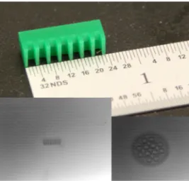
Our system is currently able to capture surface geometry with features as small as 0.8mm with spacing between fea-tures as small as 1.6mm. We evaluated out system using a number of lasercut depth targets, see figure 6. We are able to capture the overall geometry of a Lego gear, a fairly complex 2.5D object. There is some reduced accuracy due to the gel surface, but this is minimal. Deep concavities are not accurately reconstructed.
Tracking
Using a background subtraction algorithm on the recon-structed depth map, our system is able to easily detect ob-jects, fingers and tangible tools pressed into the surface. After segmentation and labeling, we are able to track these objects and classify their average and maximum depth if necessary.
We can also estimate the relative rotation and orientation of the object, providing 6 Degree of Freedom input. We esti-mate the pitch and roll, by averaging the normal vectors over the object. The rotation or yaw can be estimated by finding the major axes, but this approach only works with non-rotationally symmetric objects.
The system can also estimate the force applied by the ob-ject, based on both its depth in the gel and the surface area of the object in contact with the gel. The gel has a uniform durometer and so requires a relatively uniform force to de-form it. By integrating the area bounded by the object in the depth map, we can estimate the relative force in the Z di-rection. This could be useful for determining the pressure applied to a stylus as opposed to a flat hand.
TANGIBLE TOOLS
Our system can support input from both arbitrary objects and tagged objects such as tangible phicons (physical icons) [9]. Deformations from arbitrary objects can be mapped directly to input, while using special tagged tangi-ble controllers to pre-form specific operations.
Arbitrary objects/tools
deForm can capture, in 2.5D, arbitrary objects pressed into the gel surface. We can use these 2.5D geometries to de-form virtual meshes or to control 3D scenes. A wide variety of objects can be used to deform the surface, allowing for a diverse set of input means, beyond a single stylus. Multiple shapes can be captured at the same time.
For example, traditional wooden sculpting tools could be used to deform digital models. Many projects have sought to use traditional paintbrushes with digital interfaces [21,32], to capture particular properties and styles. Since deForm can capture both 2.5D geometry and 2D grayscale texture information, the system can function as a fast 3D scanner. Optical multitouch systems have used scans of 2D graphics, such as real photographs and docu-ments [38], to create an easy, direct way to input infor-mation. Our system adds another dimension to that intuitive approach. For example, a child could copy her toy by press-ing it into the gel. The toy could then be modified in the digital world or uploaded to represent a digital avatar in a game. We discuss the concept of “remixing” toys in the application section below.
Tangible Controls
In some applications, developers may require specific tan-gible tools to perform predefined operations. Many systems for tangible interaction choose optical markers to track tan-gible tools quickly and easily [13].
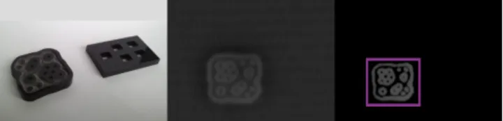
Our system is able to use 2D optical markers by detecting objects’ 2D greyscale textures. We have used Reactivision markers with our system and tracked them when pressed
Figure 6. Above: A target used to measure accu-racy with 0.8mm pins with 1.6mm spacing. Below: Left: target clearly resolved. Right: Lego gear clearly resolved
Figure 7. Tangible tools can be tracked as well from the depth map. Here a sculpting tool is background subtracted and labeled.
into the gel surface and on the surface. In addition, our sys-tem can estimate the pitch and roll of the markers through the techniques described above.
deForm also encodes marker information in physical depth rather than visible light, which can be tracked in a depth map. This approach allows for other information to be en-coded beyond a 2D pattern. In addition, the physical shape of a marker is easily changed, allowing for dynamic tags. This technique could also be applied to other depth-based input devices that do not capture 2D texture.
We encoded Reactivison information into depth markers by laser etching acrylic plastic, mapping black and white to height values. Using depth-encoded Reactivision markers, we are able to easily track these tags using just the depth map image, see figure 9. As a result of to the gel surface some error remains due to poor reconstruction of small, interior details . A modified Reactivision tag, with larger holes and fewer interior graphics, shown in figure 9, allows for a recognition accuracy of 95% when directly pressed into the material. The adjustment limits the address space but greatly improves tracking performance.
Mechanical components, such as buttons and sliders, could be added to these tangible controllers, as implemented for Slap Widgets [36]. We could encode different information into the depth of a single mechanical pin. For example, instead of a single on/off button we can have pressure sen-sitive buttons. Alternatively, rotation could be encoded in a pin by using a cam type system.
TOUCH INTERACTIONS
Our system supports traditional multitouch input, but due to its depth, it can capture more complex hand interaction.
Into the Surface Touch interactions
Iconic Gestures
Using the 2.5D depth map deForm is able to support a number of different pressure-sensitive touch gestures, such as pinching and rotating, by tracking finger positions in 3D. We can extract finger locations from the threshold depth map through thresholding and blob detection.
Beyond simply detecting gestures by finger tracking, we are able to detect certain gestures from the displacement of the gel. When an object or finger is pressed into the gel, the gel deforms around the object, increasing in height sur-rounding the perimeter of the object. When pinching, the gel is displaced between the fingers greatly. This provides
an easy way to detect pinching, by looking for areas in the depth map that have increased in height. This is just one example that highlights the differences between our system which captures the geometry of deformation, and a system which merely senses pressure.
The friction that occurs when users articulate their fingers while pressed deeply into the gel, necessitates a vocabulary of gestures based on mostly isometric relative change, ra-ther than absolute positions. This approach would also ben-efit from the passive haptic feedback that the gel provides.
Beyond iconic gestures
Because our system can detect more complex hand poses than simple touch points, there is a large opportunity to support touch interactions beyond iconic gestures. We can use the 2.5D geometry of the hands to directly manipulate a mesh, much as one would manipulate clay. This type of interaction is explored in later discussion.
Touch Interactions on top the surface
We can use the reconstructed 2D texture image of the gel surface to do basic diffuse IR multitouch sensing. In the texture image we can clearly see finger-tips finely resolved even before they greatly deform the surface, as shown in figure 10. We can use simple background subtraction and thresholding to find the finger or hand points in contact with the surface. This 2D image can then be compared to the background subtracted depth image to find touch points that are not pressing into the surface. This allows for touch interactions both on the surface and into the surface. For example, touch on the surface could be used as a hover mode, and pressing into the screen could select. Alterna-tively, touch gestures on the surface could change global application parameters, but touch gestures into the surface could change local parameters.
DISCERNING TOUCH FROM TOOLS
Many optical systems that support multitouch interaction discern touch points from other objects by looking for the size of the blobs [5]. This method is fairly robust, but is not foolproof. Un-tagged tangible tools, such as a sculpting tool, may appear similar to a finger. To resolve this ambi-guity, we propose the use of capacitive sensing in addition to optical sensing. Capacitive sensing relies on the change in capacitance between an electrode and the environment. Unlike human hands, non-conductive objects do not change the capacitance greatly. This allows deForm to distinguish between touch and tools.
Figure 8. Left to right: Raw depth map of fingers pressed into gel, Background subtraction, Thresholded 2.5D im-age
Figure 9. Depth encoded markers, designed for de-Form. Left: two laser cut reactivision markers modified to encode pattern in height. Middle: depthmap of de-pressed marker. Right: tracked and labeled marker.
Because our system relies on a very deformable and flexi-ble surface, embedding traditional capacitive sensors on the surface is not ideal. Rather, we use conductive paint on the surface. A thin layer of silver-based conductive paint is applied to surface of the gel. With this set-up the system distinguishes between the presence of a hand and a non-conductive tool.
TECHNICAL IMPLEMENTATION
The gel structure is a soft, shor 00 durometer, thermo plas-tic elastomer called Ultraflex sold by Douglas and Sturges, which is heated and cast. We have explored different du-rometer gels and found a narrow range acceptable; if the gel is too stiff, it will be more difficult to use, too loose and the gel surface will deform too easily and not retain its shape. Once painted, talc powder or cornstarch is applied to lessen the gel’s stickiness.
In order to capture each projected fringe pattern frame we synchronized the camera with the vsync line of the VGA input of a projector. We used a DLP projector because the mirror arrays can update within the frame interval, unlike many LCD projectors. Using a DLP projector, we were able to achieve rates of reconstruction at 20 Hz, by project-ing and capturproject-ing at 60 Hz. This technique should scale to much higher frame rates, as described in [40].
We calibrated the projector and cameras to correct for lens distortion using standard techniques [14]. To correct for gamma differences between projector and camera and phase errors, we implemented Zhang’s calibration for phase error correction, which uses a look up table to match the recorded phase with the ideal phase [39].
To project IR patterns, we modified our DLP by removing the IR cut filter in front of the bulb and replacing it with a cold mirror that reflects visible light and allows IR to pass [4]. We attached a IR pass filter to our Point Grey grayscale camera so as to capture only IR light.
We mounted the two projectors, IR and visible light, on the inside of a box shown in fig. 11. We mounted the camera
off to the side to observe deformations in the pattern pro-jected on the gel surface. We placed the painted gel surface on top of the box on a piece of glass.
One computer generates the patterns and another captures the geometry and displays interface elements. We created the software using C++, using Open Frameworks and openCV. We built our system on top of the open frame-works structured lighting library, ofxStructuredLighting [2].
DEMONSTRATION APPLICATIONS
We developed a number of sample applications to explore the possibilities of 2.5D input from hands, tools and arbi-trary objects.
6 Degree of Freedom Mouse
Using our depth based fiducial markers we were able to emulate a 6 DOF mouse. This type of interaction is mostly isometric and relies on relative input. In this sample appli-cation a 3D scene can be navigated by moving the tangible marker relative to its starting point in the gel. Pitch, roll and yaw are mapped to the rotation of the marker, and the cam-era can be dollied by moving the controller forward, back, right, left, up or down. This demonstrates the possibilities for using deForm to prototype new and varied 3D input devices quickly.
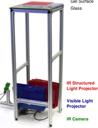
Figure 11. An image of the deForm setup. IR and Visible Light projectors mounted in 80/20 box project upwards through glass to gel surface. An IR camera off to the side captures deformations in the gel.
Gel Surface Glass IR Structured Light Projector Visible Light Projector IR Camera Figure 10. Using the reconstructed 2D grey scale texture to
provide on-the-surface multitouch. Above: Images are 2D greyscale and background subtracted greyscale image. Below: Depth information. Right: Depth information is sub-tracted from the greyscale image to find touches only on the surface, which are highlighted in red.
Sculpting Application
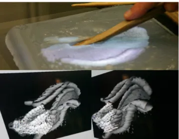
We also created a sculpting application that allows for use of real wooden sculpting tools and hands to deform digital clay. This application highlights the flexibility of the de-Form system to allow any object to deform a virtual clay model. The user views a model projected on the surface of the gel and can directly edit it through deformations. A secondary display provides an additional 3D view.
To use the raw depth map as input, we background subtract and threshold the depth image. We then break up the inter-action into sections where an object or multiple objects are deforming the surface. During the time that any object is deforming the surface, we currently find the maximum depth per pixel over that time. Once the object is removed, we add that maximum depth per pixel to the model and preview this to the user as they are deforming it.
Tangible tagged tools can be used to add reflective sym-metry, or undo actions. Hand gestures on the surface can be used to scale and rotate the scene. Currently the system is limited to only deforming a height map, but the system could be extended to manipulating and deforming a full 3D object, by rotating the model virtually.
Remixing Toys
A third application highlights the ease of 3D scanning with the deForm system. Current systems for 3D modeling are very complicated and not readily accessible to children. We present an interface for children to create their own toys. Instead of designing toys from scratch, children can copy different parts from existing toys and combine them to cre-ate a new toy.
In this application 2.5D geometry and 2D textures are cap-tured to allow children to scan their toys easily. Once cop-ied, children can erase, modify and add new geometry to make a new “remixed” toy which can be 3D printed.
Children can scan an object by pressing it into the surface. It then appears directly on the surface. Then they can use a tagged eraser tool to erase geometry, and stamp down other shapes. By making 3D scanning much easier, faster and more direct, copying can become a means for creation.
DISCUSSION AND FUTURE WORK System limitations
The resolution of our reconstruction is dependent on both the camera and projector, which makes this system limited or unsuitable for reconstructing large surfaces. The trade-off between size of the reconstructed area and the PPI is quite clear, so a table size system would have a less appeal. However, the system could be combined with a digital SLR to capture single higher resolution scans, especially when combined with projector defocusing, which removes the constraint of projector resolution [17].
Currently we are using a time-multiplexed approach to cap-ture the three required patterns to reconstruct the geometry. As a result of the time delay between each frame, large amounts of motion causes errors in reconstruction. This makes the current system ill-suited for applications such as gaming. However, smaller errors are corrected by replacing erroneous data points with information from the previous frame. Increasing frame rates could improve this problem. In addition, other phase-based structured lighting tech-niques have been developed to solve this problem. The 2 plus 1 phase approach is less sensitive to motion [40]. An-other approach is to separate the patterns by color (often Red, Green and Blue channels) as opposed to time. The current system requires a large total height due to the use of a camera and projector system, which can rarely be as thin as other approaches such as capacitive or FSR based input devices. It may be possible to reduce the height re-quired by using wider field of view cameras and short throw projectors, or by introducing some sort of wave guide, such as [15].
Figure 13. Children can create new toys by scan-ning and modifying with direct interaction. Left to Right: Pressing in a dog toy to scan it; projected feedback of the dog shape; eraser tool tracked with marker; copying a new panda head for a toy. Figure 12. An example sculpting application. Above,
users can deform 3D shapes with real sculpting tools and projected feedback. Below, two views of a sea dragon sculpted with the system.
Currently the system requires paint on the surface of the gel both to aid in reconstruction and as a projection surface. Heavy use degrades the paint over time, causing problems such as light leaks and lower quality reconstruction. Im-proving the robustness of the paint would lead to a more durable solution, and might also limit friction. Sliding and dragging are more difficult due to the friction caused by the gel and paint. Currently, we apply a lubricant, but this is an insufficient solution outside of the lab setting.
Future work
We believe that deForm points towards more flexibility and fluidity of input. Camera based systems open broad possi-bilities for novel input modalities. By combing high resolu-tion capture with a deformable, elastic surface we can begin to estimate interactions similar to sculpting clay. So much expressivity in hands that is lost when only using touch points. Previous work combined touch and 2.5D capture with physics based simulations [37], and we think deForm could be a great platform for further exploration.
We would also like to explore more interaction techniques for bimanual input, using a tool in one hand and touch in-put in another. By extending our capacitive sensing to a matrix-based approach we could locate the positions of hands and tools simultaneously to create interesting interac-tions.
We would also like to explore the use of arbitrary gel shapes as tangible controllers rather than a surface input device. The gel can be cast in any shape, such as the shape of a computer mouse. Physical affordances or buttons could be included in the form. These tools could be used on top of a traditional surface rear projection table, by using a technique similar to the Second Light system to project through the surface and onto the gel. This could be a good tool for prototyping 2.5D tangible input devices.
Finally we would like to explore how real users could in-teract with deForm. During an informal open house 50 par-ticipants including 4 children used the remixing toys exam-ple application. Initial feedback was encouraging; children particularly took to the direct manipulation provided by the system. We would like to run further evaluations of that interface and how users respond to the 2.5D input and pas-sive haptic feedback provided by deForm.
CONCLUSION
We have demonstrated a high-resolution 2.5D surface input device that can support a wide variety of input types includ-ing arbitrary objects, tangible phicon tools and touch. It can provide passive haptic feedback through a gel surface, while capturing 2.5D deformations in its surface and its 2D greyscale texture. We have shown this can be combined with invisible projection to create a 2.5D interactive de-formable surface interface, and have highlighted the tool’s strengths in 3D manipulation and digital sculpting through a number of sample applications.
ACKNOWLEDGMENTS
The authors would like to thank Matt Hirsch for his help troubleshooting computer vision problems and being
gen-erous with his time, and Hannah Perner-Wilson for her help with conductive paint. We would also like to thank Daniel Leithinger and the rest of the Tangible Media Group for their help and valuable input.
REFERENCES
1. Xbox.com | Kinect. 2010. http://www.xbox.com/en-US/kinect.
2. ofxStructured Light.
http://code.google.com/p/structured-light/.
3. Cassinelli, A. and Ishikawa, M. Khronos projector. ACM SIGGRAPH 2005 Emerging Technologies, ACM Press (2005), 10.
4. Chan, L.W., Wu, H.T., Kao, H.S., Lin, H.R., Chen, M.Y,Hsu, Jane, Hung, Y.P. Enabling beyond-surface interactions for interactive surface with an invisible pro-jection. Proc. UIST 2010, ACM Press (2010), 263–272. 5. Han, J.Y. Low-cost multi-touch sensing through
frus-trated total internal reflection. Proc. UIST 2005, ACM Press (2005), 115.
6. Hilliges, O., Izadi, S., Wilson, A.D., Hodges, S., Gar-cia-Mendoza, A., and Butz, A. Interactions in the Air : Adding Further Depth to Interactive Tabletops. Proc. UIST 2009, ACM Press (2009), 139–148.
7. Hilliges, O., Kim, D., and Izadi, S. Creating malleable interactive surfaces using liquid displacement sensing. Proc. Tabletop 2008, IEEE Press (2008), 157-160. 8. Hook, J., Taylor, S., Butler, A., Villar, N., and Izadi, S.
A reconfigurable ferromagnetic input device. Proc. UIST 2009, ACM Press (2009), 51.
9. Ishii, H. and Ullmer, B. Tangible bits. Proc. CHI 1997, ACM Press (1997), 234-241.
10. Izadi, S., Hodges, S., Taylor, S., et al. Going beyond the display. Proc. UIST 2008, ACM Press (2008), 269. 11. Jansen, Y., Karrer, T., and Borchers, J. MudPad: tactile
feedback and haptic texture overlay for touch surfaces. Proc. ITS 2010, ACM Press (2010), 11–14.
12. Johnson, M.K. and Adelson, E.H. Retrographic sensing for the measurement of surface texture and shape. Proc. IEEE CVPR 2009, IEEE Press (2009), 1070-1077. 13. Kaltenbrunner, M. and Bencina, R. reacTIVision. Proc.
TEI 2007, ACM Press (2007), 69.
14. Lanman, D. and Taubin, G. Build your own 3D scanner. ACM SIGGRAPH 2009 Courses, ACM Press (2009), 1-94.
15. Large, M.J., Large, T., and Travis, A.R.L. Parallel Op-tics in Waveguide Displays: A Flat Panel Autostereo-scopic Display. Journal of Display Technology 6, 10 (2010), 431-437.
16. Lecuyer, A., Coquillart, S., Kheddar, A., Richard, P., and Coiffet, P. Pseudo-haptic feedback: can isometric input devices simulate force feedback? Proc. IEEE Vir-tual Reality 2000, IEEE Comput. Soc, 83-90.
17. Lei, S. and Zhang, S. Flexible 3-D shape measurement using projector defocusing. Optics Letters 34, 20 (2009), 3080.
18. Malik, S. and Laszlo, J. Visual touchpad. Proc. ICMI 2004, ACM Press (2004), 289.
19. Massie, T.H. and Salisbury, J.K. The PHANTOM Hap-tic Interface: A Device for Probing Virtual Objects. Proceedings of the ASME Winter Annual Meeting Sym-posium on Haptic Interfaces for Virtual Environment and Teleoperator Systems, (1994), 295–300.
20. Nehab, D., Rusinkiewicz, S., Davis, J., and Rama-moorthi, R. Efficiently combining positions and nor-mals for precise 3D geometry. ACM Transactions on Graphics 24, 3 (2005), 536.
21. Otsuki, M., Sugihara, K., Kimura, A., Shibata, F., and Tamura, H. MAI painting brush: an interactive device that realizes the feeling of real painting. Proc. UIST 2010, ACM Press (2010), 97–100.
22. Overholt, D. The MATRIX: a novel controller for mu-sical expression. Proc. NIME 2001, AMC (2001), 1–4. 23. Piper, B., Ratti, C., and Ishii, H. Illuminating clay.
Proc. CHI 2002, ACM Press (2002), 355.
24. Rosenberg, I. and Perlin, K. The UnMousePad. Proc. SIGGRAPH 2009, ACM Press (2009), 1.
25. Sato, T., Mamiya, H., Tokui, T., Koike, H., and Fuku-chi, K. PhotoelasticTouch: transparent rubbery interface using a LCD and photoelasticity. ACM SIGGRAPH 2009 Emerging Technologies, ACM (2009), 1–1. 26. Sheng, J., Balakrishnan, R., and Singh, K. An interface
for virtual 3D sculpting via physical proxy. Computer graphics and interactive techniques in Australasia and South East Asia, (2006), 213.
27. Sile OʼModhrain. Playing by Feel: Incorporating Haptic Feedback into Computer-Based musical Instruments. 2000. https://ccrma.stanford.edu/~sile/thesis.html. 28. Sinclair, M. The haptic lens. Ext. Abstracts ACM
SIGGRAPH ’97, ACM Press (1997), 179.
29. Smith, J.D., Graham, T.C.N., Holman, D., and Borch-ers, J. Low-Cost Malleable Surfaces with Multi-Touch Pressure Sensitivity. TABLETOP 2007, IEEE (2007), 205-208.
30. Tom White. Introducing Liquid Haptics in High Band-width Human Computer Interfaces. 1998.
http://dspace.mit.edu/handle/1721.1/62938.
31. Valino Koh, J.T.K., Karunanayaka, K., Sepulveda, J., Tharakan, M.J., Krishnan, M., and Cheok, A.D. Liquid interface. Proc. ACE 2010, ACM Press (2010), 45. 32. Vandoren, P., Van Laerhoven, T., Claesen, L., Taelman,
J., Raymaekers, C., and Van Reeth, F. IntuPaint: Bridg-ing the gap between physical and digital paintBridg-ing. TABLETOP 2008, IEEE (2008), 65-72.
33. Viciana-Abad, R., Lecuona, A.R., and Poyade, M. The Influence of Passive Haptic Feedback and Difference Interaction Metaphors on Presence and Task Perfor-mance. Presence: Teleoperators and Virtual Environ-ments 19, 3 (2010), 197-212.
34. Vlack, K., Mizota, T., Kawakami, N., Kamiyama, K., Kajimoto, H., and Tachi, S. Gelforce: a vision-based traction field computer interface. Ext. Abstracts CHI 2005, ACM Press (2005), 1154–1155.
35. Vogt, F., Chen, T., Hoskinson, R., and Fels, S. A malle-able surface touch interface. ACM SIGGRAPH 2004 Sketches, ACM Press (2004), 36.
36. Weiss, M., Wagner, J., Jansen, Y., et al. SLAP widgets. Proc. CHI 2009, ACM Press (2009), 481.
37. Wilson, A.D., Izadi, S., Hilliges, O., Garcia-Mendoza, A., and Kirk, D. Bringing physics to the surface. Proc. UIST 2008, ACM Press (2008), 67.
38. Wilson, A.D. TouchLight. Proc. ICMI 2004, ACM Press (2004), 69.
39. Zhang, S. and Yau, S.-T. Generic nonsinusoidal phase error correction for three-dimensional shape measure-ment using a digital video projector. Applied Optics 46, 1 (2007), 36.
40. Zhang, S. Recent progresses on real-time 3D shape measurement using digital fringe projection techniques. Optics and Lasers in Engineering 48, 2 (2010), 149-158.