READ THESE TERMS AND CONDITIONS CAREFULLY BEFORE USING THIS WEBSITE.
https://nrc-publications.canada.ca/eng/copyright
Vous avez des questions? Nous pouvons vous aider. Pour communiquer directement avec un auteur, consultez la
première page de la revue dans laquelle son article a été publié afin de trouver ses coordonnées. Si vous n’arrivez pas à les repérer, communiquez avec nous à PublicationsArchive-ArchivesPublications@nrc-cnrc.gc.ca.
Questions? Contact the NRC Publications Archive team at
PublicationsArchive-ArchivesPublications@nrc-cnrc.gc.ca. If you wish to email the authors directly, please see the first page of the publication for their contact information.
This publication could be one of several versions: author’s original, accepted manuscript or the publisher’s version. / La version de cette publication peut être l’une des suivantes : la version prépublication de l’auteur, la version acceptée du manuscrit ou la version de l’éditeur.
Access and use of this website and the material on it are subject to the Terms and Conditions set forth at Effect of floor size on impact sound levels
Warnock, A. C. C.
https://publications-cnrc.canada.ca/fra/droits
L’accès à ce site Web et l’utilisation de son contenu sont assujettis aux conditions présentées dans le site LISEZ CES CONDITIONS ATTENTIVEMENT AVANT D’UTILISER CE SITE WEB.
NRC Publications Record / Notice d'Archives des publications de CNRC: https://nrc-publications.canada.ca/eng/view/object/?id=e53939f5-6c32-4ca2-80ed-c12665c72699 https://publications-cnrc.canada.ca/fra/voir/objet/?id=e53939f5-6c32-4ca2-80ed-c12665c72699
EFFECT OF FLOOR SIZE ON IMPACT SOUND LEVELS
A.C.C. Warnock
National Research Council Canada, Institute for Research in Construction
51.5
Abstract
Over the years, many have expressed reservations about the usefulness of impact sound pressure level measurements made with the standard 1, 2 ISO tapping machine. In countries where wood-joist and other light-weight constructions are used, current concern focuses on the frequencies around and below 100 Hz where such floors transmit much sound energy yet where standard tapping machine tests require no measurement. Recent research 3, 4, 5 has examined the possibility of new impactors, measurements at lower frequencies or modified ratings procedures to improve correlation with subjective reactions. When Blazier4
compared his measurements of sound pressure levels generated by walkers with those obtained at NRC, he realized that floor size was likely to be an important parameter. He found that the maximum sound energy occurred around 20 Hz when a joist floor measuring 3 × 4 m with 4 m long joists was walked on. McKell6 also found similar results on a timber joist floor of the same lateral dimensions. For floors tested at NRC with joists 2.4 m long, the maximum sound energy occurred around 50 Hz. This paper takes a preliminary look the significance of floor size, not just at low frequencies but also at standard test frequencies. Résumé
Au cours des années, beaucoup ont formulé des réserves concernant l’utilité des mesures du niveau de pression des bruits d’impact réalisées avec la machine à chocs
normalisée de l’ISO. Dans les pays où l’emploi de solives et d’autres types de constructions légères sont courants, on se préoccupe actuellement des fréquences avoisinant 100 Hz ou se situant au-dessous; dans ce cas, de tels planchers transmettent beaucoup d’énergie sonore mais les essais normalisés à la machine à chocs n’exigent pas de mesure. Lors de travaux de recherche récents, on a étudié la possibilité d’utiliser de nouveaux dispositifs d’impact, d’effectuer des mesures à des fréquences plus basses ou de modifier les méthodes de classement afin d’améliorer la corrélation avec les réactions subjectives.
BACKGROUND
In Ref. 7 it was shown that the maximum dynamic deflection obtained for a floor
proportional to 1 / kfn. For a joist floor, it can be shown that the maximum velocity is
proportional to L5 where L is the span of the joist. For a monolithic slab, fn is proportional to
(1/a2 + 1/b2), where a and b are the slab dimensions and kfn is proportional to (1/a2 + 1/b2)3ab. If we take a ≈ b ≈ L, then we see that the maximum velocity is proportional to L4. This simple analysis suggests that changing the size of a floor of a particular construction, changes the lowest resonance frequency and the radiated sound energy at that frequency. One would also expect changes in radiated sound energy at frequencies near other low-order modes of the floor. This is in qualitative accord with observation. If test procedures that extend to frequencies below 100 Hz are contemplated, the issue of the influence of specimen size on test reproducibility should be considered. There may also be effects due to specimen size within the frequency range of current test standards. This paper presents a preliminary look at this matter.
MEASUREMENTS
The new facility8 at NRC has a floor opening measuring 3.8 × 4.7 m and room volumes of about 175 m3. The floor in the old facility measures 2.4 × 2.4 m and the receiving room volume is 65 m3. Two nominally identical floors were tested in both facilities. These were 1) a 150 mm thick slab of reinforced concrete and 2) a wood-joist floor comprising a layer of 16 mm plywood, 240 mm wood-joists, 90 mm glass fiber batts, 13 mm resilient metal
channels, and 16 mm gypsum board. The joists were 400 mm apart and measured 2.4 m in the old and 3.8 m in the new facility. In both facilities, the same measurements were made, with the same techniques and instrumentation. Impact sound insulation1,2 was measured using the ISO machine, as were peak levels due to impacts from a tire machine and a male walker. The tire machine originally satisfied JIS14189 but was modified3 to reduce the maximum force delivered to the floor. Peak sound pressure levels were measured with a single microphone 1 m below the ceiling in the room below (which was deadened with sound absorbing material). Although not directly of concern for this paper, standard
measurements of airborne sound transmission loss 10, 11 were also made and are reported here for interest.
The joist floor in the new facility was constructed to make it easy to cut the floor into two parts. At one location in the floor, two joists were placed about 25 mm apart and the headers supporting the joists were installed in two pieces. After testing as a complete assembly, the floor was cut into two parts along the line between these two joists. One part measured 3.8 × 2.8 m and the other 3.8 × 1.9 m. The larger of the two parts was then tested as a separate unit. To reduce any radiation from the second smaller part, it was covered with an additional shield.
COMPARISON BETWEEN FACILITIES 150 mm CONCRETE SLAB.
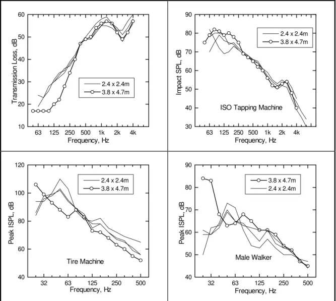
Figure 1 shows the results for the two 150 mm concrete slabs. The airborne sound transmission loss data are in reasonable agreement in the mid frequencies. Differences at low frequencies may be attributed to the floor size or the smaller receiving room volume; other work in this laboratory suggests that room volume is important at these low
frequencies but the specimen size may be too. The curve for the smaller floor slab shows some peaks and valleys that are probably associated with the resonances in the floor.
In the plots for the ISO tapping machine levels, there are pronounced peaks in the spectrum for the smaller floor but only a single peak at a lower frequency in the spectrum for the larger floor. The agreement between the two floors for the tapping machine
measurement is much poorer than that for the airborne sound transmission measurement. Similarly, in the results for the tire machine and the walker, the maximum response occurs at two distinctly different frequencies. The frequency where the peak occurs for the large floor is about half that for the small one. According to the simple model above, the level difference at the fundamental resonance frequency should be about 19 dB. This is in reasonable accord with the result for the tire machine but not for the walker. There are other factors that could influence the levels generated by the walker. The difference in floor size allowed a different walking pattern and may well have caused a difference in gait. Even
63 125 250 500 1k 2k 4k 20 40 60 80 100 2.4 x 2.4 m 3.8 x 4.7 m T ran sm iss ion Lo ss, dB Frequency, Hz 63 125 250 500 1k 2k 4k 40 50 60 70 80
ISO Tapping Machine
2.4 x 2.4 m 3.8 x 4.7 m Im p a ct S P L , d B Frequency, Hz 3 2 6 3 1 2 5 2 5 0 5 0 0 3 0 4 0 5 0 6 0 7 0 8 0 9 0 1 0 0 1 1 0 T ir e M a c hine 2 .4 x 2 .4 m 3 .8 x 4 .7 m Pe a k I SPL , d B F r e q ue nc y , Hz 32 63 125 250 500 30 40 50 60 70 80 Male Walker 2.4 x 2.4 m 3.8 x 4.7 m Pea k I S PL , d B Frequency, Hz
Figure 1: Airborne sound transmission loss and impact sound levels for two 150 mm thick concrete slabs measuring 3.8 × 4.7 m and 2.4 × 2.4 m.
strongly influenced by the floor size. The implication of this result for possible standardized laboratory measurement using similar impactors appears quite serious, but more data are definitely needed to clarify this issue.
COMPARISON BETWEEN FACILITIES WOOD-JOIST FLOORS
Figure 2 shows results for wood-joist floors tested in both facilities. Data here give a less clear picture. In each plot in the figure, the narrow lines show results for floors that have wood trusses as well as for floors with wood-joists. These are included because in a longer series of measurements they were found to behave very much like solid joists.
Figure 2: Airborne and impact sound transmission for wood-joist floors with joist lengths of 2.4 and 3.8 m.
The airborne results for the small floors agree well with each other but differ from the larger floor from 63 Hz to 315 Hz. There is no consistent pattern in the ISO machine results from 50 to 250 Hz. Part of the variation that is seen in this region is due to variations in construction. Other work at NRC has shown that for stud walls and joist floors, the distance
63 125 250 500 1k 2k 4k 10 20 30 40 50 60 2.4 x 2.4m 3.8 x 4.7m T ran sm iss ion Lo ss, dB Frequency, Hz 63 125 250 500 1k 2k 4k 30 40 50 60 70 80 90
ISO Tapping Machine
2.4 x 2.4m 3.8 x 4.7m Im pact S P L, d B Frequency, Hz 32 63 125 250 500 40 60 80 100 120 Tire Machine 2.4 x 2.4m 3.8 x 4.7m Pea k I S PL , d B Frequency, Hz 32 63 125 250 500 40 50 60 70 80 90 Male Walker 3.8 x 4.7m 2.4 x 2.4m Pea k I S PL , d B Frequency, Hz
between studs or joists and the spacing and tightness of the screws can strongly influence the sound transmission for several bands on either side of 125 Hz. The studs or joists divide the plywood or gypsum board into smaller panels and resonances in these panels strongly affect the sound transmission. Changes of several decibels can be made at times simply by
slackening screws and changing the depth of a resonance. One may conclude from such data that while floor size is an issue, there are other factors that cause results for nominally identical floors to be significantly different.
The results for the tire and the walker are similar from the point of view of frequency; the smaller floors show peaks in the response at 50 Hz while the larger floor has a peak around 25 Hz. The peak levels for the tire (although at different frequencies) have about the same amplitude while the levels from the walker are about 10 dB different. A difference of around 20 dB is expected from the simple treatment given above which evidently does not work well with these kinds of floors.
RESULTS FOR CUT-DOWN FLOOR
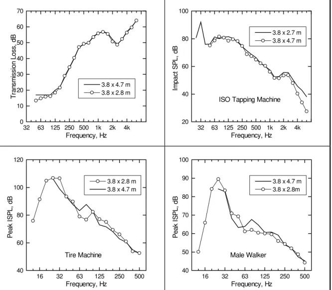
The simple analysis given at the beginning predicts that reducing the size of the 3.8 × 4.7 m floor by cutting it parallel to a joist should not significantly change the results; the fundamental resonance will not change. The results in Figure 3 support this prediction. Both standardized measurements agree well although there are differences above 3150 Hz with the ISO tapping machine. The measurements show that the ISO machine generates adequate amounts of energy below 100 Hz and suggest that it may be a useful impact source for testing below 100 Hz as suggested by Bodlund and in Ref. 3. While there appears to be some differences between the tire and walker responses around 100 Hz, the two results are fairly close together. This set of data supports the simple analysis which says that the joist length is the dominant parameter controlling the floor response.
CONCLUSIONS
The data presented here are from a very limited set. With time, more comparisons will become available. However, we may say with some certainty that when measurements are made to frequencies lower than those presently standardized in ISO and ASTM test methods, then the floor size is an important parameter. If new standards do not place some limits on joist length or slab dimensions, reproducibility of the test procedures will not be good enough. With standard tests, the floor size may be an issue, but there are other factors which complicate the comparisons and the data shown here do not allow unequivocal conclusions.
REFERENCES
1. ISO 140/VI Laboratory measurements of Impact Sound Insulation of Floor Elements
2. ASTM E492, Laboratory Measurement of Impact Sound Transmission through Floor-Ceiling Assemblies using the Tapping Machine.
3. Warnock, A.C.C. "Investigation of the Tire Impact Machine as a Standard Device for Rating Impact Sound Transmission of Floors", NRCC Report CR6132.2.
4. W.E. Blazier Jr. and R.B. Dupree, “Investigation of Low-Frequency Footfall Noise in Wood-Frame Floor Construction”, JASA in press.
5. Bodlund, Kaj, "Rating of Impact Sound Insulation between dwellings", J. Sound and Vibration, 102(3), p381, 1985.
Thesis, Heriot-Watt University, Edinburgh, April 1991.
7. E.E. Ungar and R.W. White, “Footfall-Induced Vibrations of Floors Supporting Sensitive Equipment”, Sound and Vibration, October 1979, p10.
8. R.E. Halliwell, J.D. Quirt, and A.C.C. Warnock, “Design and Commissioning of a New Floor Sound Transmission Facility”, Proc INCE 93, p995
9. JIS 1418 Japanese National Standard describing impact testing of floors.
10. ASTM E90 Laboratory Measurement of Airborne Sound Transmission Loss of Building Partitions. 11. ISO 140/III Laboratory measurements of airborne sound insulation of building elements
32 63 125 250 500 1k 2k 4k 0 10 20 30 40 50 60 70 3.8 x 4.7 m 3.8 x 2.8 m Tr an sm ission L o ss, d B Frequency, Hz 32 63 125 250 500 1k 2k 4k 20 40 60 80 100
ISO Tapping Machine
3.8 x 2.7 m 3.8 x 4.7 m Im pact S P L, d B Frequency, Hz 16 32 63 125 250 500 40 60 80 100 120 Tire Machine 3.8 x 2.8 m 3.8 x 4.7 m Pea k I S PL , d B Frequency, Hz 16 32 63 125 250 500 40 50 60 70 80 90 100 Male Walker 3.8 x 4.7 m 3.8 x 2.8m Pea k I S PL , d B Frequency, Hz
Figure 3: Airborne and impact sound transmission for a single wood-joist floor cut parallel to the joists to form two sizes of floor.