Publisher’s version / Version de l'éditeur:
Vous avez des questions? Nous pouvons vous aider. Pour communiquer directement avec un auteur, consultez la
première page de la revue dans laquelle son article a été publié afin de trouver ses coordonnées. Si vous n’arrivez pas à les repérer, communiquez avec nous à PublicationsArchive-ArchivesPublications@nrc-cnrc.gc.ca.
Questions? Contact the NRC Publications Archive team at
PublicationsArchive-ArchivesPublications@nrc-cnrc.gc.ca. If you wish to email the authors directly, please see the first page of the publication for their contact information.
https://publications-cnrc.canada.ca/fra/droits
L’accès à ce site Web et l’utilisation de son contenu sont assujettis aux conditions présentées dans le site
LISEZ CES CONDITIONS ATTENTIVEMENT AVANT D’UTILISER CE SITE WEB.
Student Report (National Research Council of Canada. Institute for Ocean Technology); no. SR-2005-02, 2005
READ THESE TERMS AND CONDITIONS CAREFULLY BEFORE USING THIS WEBSITE.
https://nrc-publications.canada.ca/eng/copyright
NRC Publications Archive Record / Notice des Archives des publications du CNRC :
https://nrc-publications.canada.ca/eng/view/object/?id=356c61ab-ce37-4039-9124-312ad7ec9adb https://publications-cnrc.canada.ca/fra/voir/objet/?id=356c61ab-ce37-4039-9124-312ad7ec9adb
Archives des publications du CNRC
For the publisher’s version, please access the DOI link below./ Pour consulter la version de l’éditeur, utilisez le lien DOI ci-dessous.
https://doi.org/10.4224/8895997
Access and use of this website and the material on it are subject to the Terms and Conditions set forth at
Industry company profile: Institute for Ocean Technology (IOT) offshore evacuation systems
REPORT NUMBER
SR-2005-02
NRC REPORT NUMBER DATE
April 2005
REPORT SECURITY CLASSIFICATION
Unclassified
DISTRIBUTION
Unlimited
TITLE
INDUSTRY COMPANY PROFILE: INSTITUTE FOR OCEAN TECHNOLOGY (IOT) OFFSHORE EVACUATION SYSTEMS
AUTHOR(S)
Colin Power
CORPORATE AUTHOR(S)/PERFORMING AGENCY(S)
Institute for Ocean Technology, National Research Council, St. John’s, NL
PUBLICATION
SPONSORING AGENCY(S)
Institute for Ocean Technology, National Research Council, St. John’s, NL
IOT PROJECT NUMBER NRC FILE NUMBER
KEY WORDS
Evacuation systems, Conventional Davit Lifeboat Freefall Lifeboat PAGES v, 17, App. A-D FIGS. 11 TABLES SUMMARY
This report composes an Industry Company Profile (ICP), which is an obligation to the faculty of Engineering Co-op office. This report is separated into three sections:
1. Industry Profile on offshore evacuation systems.
2. Company Profile on the Institute for Ocean Technology (IOT). 3. My role as an engineering work term student.
In the Industry Profile I discuss the history of evacuation systems, discussing what type of evacuation systems have been used and are currently being used and the advantages and disadvantages of each.
The Company Profile component of this report focuses on the Institute for Ocean Technology and mainly its first-class facilities. I also discuss the lifeboat performance project, and the life raft operational performance project.
The last section of my profile constitutes my role as an engineering work term student in the company. It deals with my involvement with both the full scale and model scale tests on life rafts in January and April of 2005. It also discusses how I played an active role in the analysis of lifeboat tests in ice.
ADDRESS National Research Council
Institute for Ocean Technology Arctic Avenue, P. O. Box 12093 St. John's, NL A1B 3T5
Institute for Ocean Institut des technologies
Technology océaniques
INDUSTRY COMPANY PROFILE: INSTITUTE FOR OCEAN
TECHNOLOGY (IOT) OFFSHORE EVACUATION SYSTEMS
SR-2005-02
Colin Power
SUMMARY
This report composes an Industry Company Profile (ICP), which is an
obligation to the faculty of Engineering Co-op office. This report is separated into
three sections:
1. Industry Profile on offshore evacuation systems.
2. Company Profile on the Institute for Ocean Technology (IOT).
3. My role as an engineering work term student.
In the Industry Profile I discuss the history of evacuation systems,
discussing what type of evacuation systems have been used and are currently
being used and the advantages and disadvantages of each.
The Company Profile component of this report focuses on the Institute for
Ocean Technology and mainly its first-class facilities. I also discuss the lifeboat
performance project, and the life raft operational performance project.
The last section of my profile constitutes my role as an engineering work
term student in the company. It deals with my involvement with both the full
scale and model scale tests on life rafts in January and April of 2005. It also
discusses how I played an active role in the analysis of lifeboat tests in ice.
TABLE OF CONTENTS Page SUMMARY i TABLE OF CONTENTS ii LIST OF APPENDICES iv LIST OF FIGURES v
1.0 INDUSTRY PROFILE: OFFSHORE EVACUATION SYSTEMS 1
1.1 Evacuation Systems 1
1.2 Primary Evacuation Systems 1
1.2.1 Conventional Davit Released Lifeboat 2
1.2.2 Freefall Lifeboat 3
1.2.3 Madrock Lifeboat 3
1.3 Secondary Evacuation Systems 4
2.0 COMPANY PROFILE: INSTITUTE FOR OCEAN TECHNOLOGY 5
2.1 Facilities 6
2.1.1 Offshore Engineering Basin (OEB) 6
2.1.2 Towing Tank 7
2.1.3 Ice Tank 8
2.2 Projects 9
3.0 STUDENTS ROLE AT IOT 10
3.1 Full-Scale Life raft Testing 10
3.1.1 Engineering Tests 10
3.1.2 Human Factors 11
3.2 Analysis of Lifeboat Tests in Ice 12
3.2.1 Straight Run Analysis 13
3.2.2 Turning Circles Analysis 13
3.2.3 Accelerations 14
3.3 Model-Scale Life raft Testing 14
4.0 CONCLUSIONS 15
5.0 BIBLIOGRAPHY 16
List of Appendices
APPENDIX A IOT’s Major Facilities A1
APPENDIX B Human Factors Preliminary Analysis A2 APPENDIX C Analysis of Lifeboat Tests in Ice A3 APPENDIX D Plotted Tracks and Acceleration Graph A4
List of Figures
Figure 1.1 Conventional Davit Lifeboats Figure 1.2 Freefall Lifeboat
Figure 1.3 Madrock Lifeboat Figure 1.4 Life Raft
Figure 1.5 Chute
Figure 2.1 Offshore Engineering Basin (OEB) Figure 2.2 Towing Tank
Figure 2.3 Ice Tank
Figure 3.1 Engineering Testing (16-person raft) Figure 3.2 Human Factors (16-person raft)
Figure 3.3 Model-Scale Life Raft Testing
2.0 INDUSTRY PROFILE: OFFSHORE EVACUATION SYSTEMS
As offshore petroleum exploration in Canadian waters grows continuously,
the need for improved offshore safety rises also. Companies will stop at nothing
to discover potential oil fields, including exploration in more challenging
environments. The unique weather conditions (wind and waves, cold
temperatures, and ice) of the Canadian coast must be addressed. Until recently,
not much effort has been put forth to investigate ways in which offshore
evacuations systems can be improved.
1.1 Evacuation Systems
The two main categories of evacuation systems are primary evacuation
systems and secondary evacuation systems. Each of these has their own
advantages and disadvantages and one may be more suitable for certain
situations than the others.
1.2 Primary Evacuation Systems
Primary Evacuation Systems includes lifeboats, and more specifically
Totally Enclosed Motor Propelled Survival Crafts (TEMPSC). These lifeboats
include the davit released Convention lifeboat, the gravity induced Freefall
lifeboat, and the Madrock lifeboat. The obvious advantage of these lifeboats is
that, since they are enclosed, they protect occupants from fire, gas, and the
harsh environment of wind, waves, and freezing temperatures.
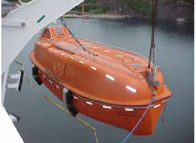
1.2.1 Conventional Davit Released Lifeboat
The Conventional lifeboat is the most commonly used lifeboat on ships
and offshore structures. It is released by the Davit system (shown in Figure 1.1),
which slowly lowers the lifeboat into the water adjacent to the abandoned vessel.
The risk involved here is the launch. There is the possibility of the hook
mechanism not releasing at all, in which the lifeboat will be at the mercy of the
vessel from which it was launched. There is also a risk of the lifeboat colliding
with the support boat on its way into the water. In addition to this, the round
shape of the conventional design causes it to experience a much greater roll
frequency than the other models, which can result in extreme discomfort of its
passengers.
Figure 1.1 Conventional Davit Lifeboat
1.2.2 Freefall Lifeboat
This lifeboat design gets its name from its ability to be dropped into the
water as opposed to being lowered like the other boats, thus providing a speedy
getaway from the source of danger. In the event of evacuation, this lifeboat is
launched from launch ramp, similar to a slide, on the deck of a boat or structure,
and “dives” into the ocean. Its shape is such that it decelerates at a minimal rate
so that injuries are minimized. This launching method, however, is also the
lifeboats downfall. The decelerations experienced by the occupants at the time
of impact with the water, is often times enough to cause injury. Furthermore, this
launching system is obviously inappropriate for areas where evacuation may take
place near, or in pack ice.
Figure 1.2 Freefall Lifeboat
1.2.3 Madrock Lifeboat
The Madrock Lifeboat is a design of MadRock Marine Solutions Inc. This
company is a part of OTEC (Ocean Technology Enterprise Center). Like the
Conventional lifeboat, this boat also uses the Davit launching systems, and
exhibits all the advantages and disadvantages that are expected from the Davit
system. The Madrock, however, is a more powerful lifeboat, which is thought to
be the primary reason that it handles better then the other two designs in all
types of weathers. Another advantage is that it has a forward canopy with
windows in the sides, front, and back, which provides better view for the
coxswain.
Figure 1.3 Madrock Lifeboat
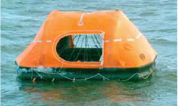
1.3 Secondary Evacuation Systems
Secondary Evacuation Systems, such as life rafts and chutes, should only
be used in the event that Primary Evacuation Systems are not available. Life
rafts such as the one shown in figure 1.4, are deployed to the water from the
support vessel, and inflate automatically on impact. A chute is then used to get
personnel from vessel to the life raft (figure 1.5). Since these rafts are not motor
propelled, the occupants must use paddles to escape the endangered vessel, as
the raft provides minimal protection from hazards such as fire, or the unforgiving
environment. At certain wave frequencies, the life raft is very susceptible to
capsizing, which greatly increases the risk of occupants becoming exposed to
frigid waters.
Figure 1.4 Life raft
Figure 1.5 Chute
2.0 COMPANY PROFILE: INSTITUTE FOR OCEAN TECHNOLOGY
The Institute for Ocean Technology (IOT) is a branch of the National
Research Council of Canada and is located on Memorial University’s Campus in
St. John’s, Newfoundland. IOT conducts ocean engineering research by
replicating ocean environments, enhancing the performance of oceanic systems,
and developing revolutionary technologies that assist the Canadian offshore
industry. With its combination of knowledge, experience, and outstanding
facilities, IOT has gained both national and international reputation as being a
world-class ocean engineering establishment.
2.1 Facilities
The three major facilities at the IOT are the Offshore Engineering Basin
(OEB), Towing Tank, and Ice Tank (found in Appendix A). The Institute also has
specialized equipment such as a cavitation tunnel, yacht dynamometer, a five
axis-milling machine, and a planar motion mechanism. IOT offers on site shops
for electronics, carpentry, machining, fiber glassing, welding, and painting.
These shops are occupied with experienced experts in these fields, and can be
consulted at any time by the researchers during an ongoing project.
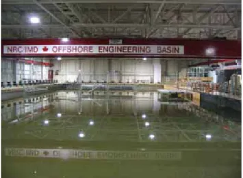
2.1.1 Offshore Engineering Basin (OEB)
The basin is seventy-five meters in length and thirty-two meters in width,
with an adjustable water depth of 0.1 to 3.0 meters. One hundred and sixty-eight
(168) hydraulically activated wavemaker segments produce waves of variable
wave height and wave period. These segments are banked along the south and
west sides of the tank. The facility also has fixed and moveable passive wave
absorbers on opposing sides of the wavemakers which act as a beach. Wind in
the OEB is created by a collection of twelve fans, which have a maximum gusting
capability of twelve meters per second at a distance of ten meters. The
advantages that the OEB has over other basins are its ability to generate oblique
and multi-directional waves as well as generate surface currents. This facility,
along with its instrumentation and data acquisition, is one of the most advanced
engineering basins in the world. The following tests can be performed in the
OEB:
Ship or structure behavior in multi-directional seas Maneuvering and station keeping
Tow out, set down and operation of offshore structures Sea keeping in oblique waves
Figure 2.1 Offshore Engineering Basin (OEB)
2.1.2 Towing Tank
The Towing Tank is a rectangular tank 200m in length, 12m in width and
7m in depth. Models are towed the length of the tank in either calm waters or
waves by an 80,000 kg carriage which spans across the width of the tank. The
carriage outputs 746 kW of power, and has a speed range of 0.001 m/s - 10.0
m/s. Banks of digital computer controlled wavemakers along the west side of the
tank generate regular or irregular waves. Wind is created with the exact same
bank of fans as used in the OEB. The following tests may be performed in the
Towing Tank:
Resistance and Propulsion Wave survey
Flow visualization Propeller open water Sea keeping
Floating and moored structures Loads due to wind and current Lift and drag
Dynamics of underwater vehicles Manikins and human subjects
Submarines and underwater vehicles
Figure 2.2 Towing Tank
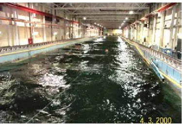
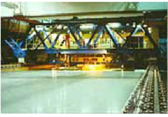
2.1.3 Ice Tank
The Ice Tank is a rectangular tank 90m in length, 12m in width and 3m in
depth, which makes it the largest ice tank in the world. Models may be towed,
self propelled, or moored a simulated Arctic environment. The 80,000 kg
carriage spans across the width of the tank andoutputs 745 kW of power, and
has a speed range of 0.0002 m/s - 4.0 m/s. Refrigeration is made possible by an
ammonia-based system with 26 evaporators. Temperature is controlled by
computers and ranges from -30°C to +15°C. The typical ice growth rate in the
tank is about 3.0mm/hr at -25°C, and ice can grow up to a thickness of 15 cm.
The following tests can be done in the Ice Tank:
Ship resistance, ship self-propulsion and maneuvering in ice Ice forces on moored and fixed structures
Offshore simulation
Figure 2.3 Ice Tank
2.2 Projects
Two projects that I have been involved with that are currently ongoing at IOT
are the lifeboat performance project, and the life raft operational performance
project. The vision of these projects is to improve the safety of personnel at sea.
The main collaborators of this project are MUN School of Human Kinetics and
Recreation, MUN Engineering, the Marine Institute, and the Offshore Safety and
Survival Center (OSSC). These projects assess the technical performance of
evacuation systems and observe the effects of the environment on them.
Evaluation of human factors and training also takes place. After tests are
performed, inadequacies of current regulations are addressed, and research
findings are applied to improve training of offshore workforce.
3.0 STUDENTS ROLE AT IOT
As a work term student at IOT, I worked under Lawrence Mak, a research
officer, and worked within the Escape, Evacuation, and Rescue (EER) research
team. I was involved with studies on Totally Enclosed Motor Propelled Survival
Crafts (TEMPSC) in ice, as well as tests on 16-person, and 42-person life rafts.
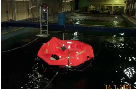
3.1 Full-Scale Life raft Testing
The full-scale life raft testing took place during the month of January 2005
in the Towing Tank. The tests involved towing a 16-person life raft in regular and
irregular types of waves and had two components: human factors, and
engineering.
3.1.1 Engineering Tests
As the raft is being towed down the tank, a program called Qualisys Track
Manager (QTM) continuously plots the rafts X, Y, and Z positions. QTM is a
modern, Windows-based motion capture software that allows the user to perform
two-dimensional as well as three-dimensional motion capture. It does this by
recording the positions of Qualisys markers that have known relative positions on
a body. This motion capture also includes the body’s yaw, pitch, and roll. In
addition to this, load cells were located on the towline, and drogue line, which
recorded the loads at these points. Other data, such as wave height, raft air
pressure, carriage position, accelerations, etc. were also plotted during each run.
My responsibility was to check these channels after each run, using the software
Igor Pro to ensure that all of the data was being collected and looked reasonable.
In the event that a channel looked irrational, I reported it, and ensured that the
problem was fixed before further tests were completed. I was also responsible
for retrieving the drogue after each run as well as deploying it at the beginning.
Figure 3.1 Engineering Testing (16-person raft)
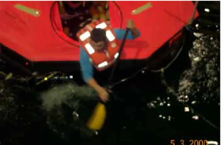
3.1.2 Human Factors
Dr. Scott Mackinnon of Memorial’s faculty of Human Kinetics and
Recreation headed up the Human Factors experiments. For these tests, eight 75
kg manikins were tied to the raft in a seated position. One of the manikins had a
Motionpak located in its chest, which recorded the yaw, pitch, roll, and
translational accelerations that a human would experience. Also for each run;
two human subjects inside the raft performed specific tasks. The tasks included
closing the canopy, movements in the raft, bailing, paddling, and deploying and
retrieving a drogue. Each of the tasks was performed in calm waters as well as
waves, and comparisons were made. I was responsible for checking the
Qualisys data after each run, but it was also very important to verify that the
dummy Motionpak data was being collected. For these tests, there were voltage
signals transmitted when the human subjects began and ended their tasks, which
is how I determined the time it took each subject to complete a task. I also
participated in these studies as a human subject. Preliminary analysis of human
factors tests can be found in Appendix B.
Figure 3.2 Human Factors (16-person raft)
3.2 Analysis of Lifeboat Tests in Ice
For the majority of my work term, I analyzed data from tests that were
done prior to my work term on 1:7 TEMPSC models in ice. In my analysis, I used
a program called Igor Pro. Igor Pro is an integrated program for analyzing,
transforming, and presenting experimental data. The fascinating thing about Igor
Pro is that it has its own built-in programming environment, which allows the user
to display data in such a manner that is simple and most convenient for that
individual. For example, in this test series a procedure was developed to display
up to twenty-six graphs of motions and waveforms that were important to the
experiments with the simple click of a mouse button. My analysis was broken
into straight run analysis, turning circle analysis, and accelerations. Each
examination required a different procedure and special data. Plotted graph that
were used during analysis for the Conventional model can be found in Appendix
C.
3.2.1 Straight Run Analysis
During the straight run tests, the TEMPSC models were required to
maneuver through the ice in a “straight line”. The important data for this analysis
was elapsed time, total distance, and mean speed. I got all of this data from
graphs that were plotted during the test runs. After analyzing the data,
comparisons were made between the Conventional, Freefall, and Madrock
models.
3.2.2 Turning Circles Analysis
The turning circles analysis required the lifeboat models to complete four
or five full circles if possible. Circles were performed turning port and starboard.
The most important data for this was the mean diameter of the circles. I also
determined the roll angles for each run. The Madrock model proved to turn the
best with a much smaller turning diameter than the other two models. The
plotted tracks of the Conventional models straight run and a turning circle are
located in Appendix D.
3.2.3 Accelerations
Before analyzing the accelerations, I had to combine the Y acceleration
and X acceleration in Igor Pro to get the resultant acceleration. Then I analyzed
the most extreme accelerations during each run. This was arguably the most
important analysis, as it would be able to determine whether or not passengers
could be thrown from their seats or experience whiplash.
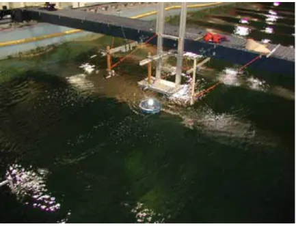
3.3 Model-Scale Life raft Testing
During the month of April, we performed tests on a 1:7 scale 16-person life
raft, which was manufactured by Newfoundland Marine. I had the same
responsibilities as I did with the full-scale model testing, which included
preliminary checks of the data recorded in each channel. I was also responsible
for any configuration changes that needed to be made to the raft itself, such as
maintaining air pressure, changing batteries, different ballast conditions, etc. The
results of these tests will be compared with the results from the full-scale
engineering tests in the near future. Unfortunately, I will not be here to observe
these outcomes.
Figure 3.3 Model-Scale Life Raft Testing
4.0 CONCLUSIONS
During my second work term at the IOT under the supervision of
Lawrence Mak, I have learned a great deal about offshore safety, data analysis,
and the overall organization of a project. During my first work term here, I
learned a lot about physical model testing as well as full scale testing in the
institutions world-class facilities. Throughout this work term, I acquired an
abundance of knowledge on the analysis of the data that comes from these
physical tests. My research team was a great source of knowledge, and the IOT
is a superb place to pursue a career.
5.0 BIBLIOGRAPHY
• National Research Council, Institute for Marine Dynamics (2003).
Proposal: Lifeboat Rescue Performance: Survivability and Recovery.
• “Presentation to Management on Marine Safety Program”, [Presentation], (February, 2005).
• “Escape Evacuation and Rescue Survivability Testing”, [Report], Colin Power, (August 2004).
• National Research Council (n.d./2003). IOT-Offshore Engineering Basin [WWW document]. URL http://iot-ito.nrc-cnrc.gc.ca/facilities_oeb.html
• National Research Council (n.d./2003). IOT-Towing Tank [WWW document]. URL http://iot-ito.nrc-cnrc.gc.ca/facilities_tt.html
• National Research Council (n.d./2003). IOT-Ice Tank [WWW document].
URL http://iot-ito.nrc-cnrc.gc.ca/facilities_it.html
• National Research Council (n.d./2003). Facilities [WWW document]. URL
http://iot-ito.nrc-cnrc.gc.ca/facilities.html
• National Research Council (n.d./2003). Research [WWW document]. URL
http://iot-ito.nrc-cnrc.gc.ca/research.html
• “Madrock Marine Solutions Inc.”, Products [WWW document]. URL
http://www.madrock.ca/view.php?sub_cat_id=5
• “Qualisys Track Manager User Manual” (2002). Qualisys Medical AB [WWW document]. URL http://qualisys.se
• WaveMetrics Inc. (2000) “Getting Started, Igor Pro Version 4.0” Volume 1 page 1-2