READ THESE TERMS AND CONDITIONS CAREFULLY BEFORE USING THIS WEBSITE.
https://nrc-publications.canada.ca/eng/copyright
Vous avez des questions? Nous pouvons vous aider. Pour communiquer directement avec un auteur, consultez la
première page de la revue dans laquelle son article a été publié afin de trouver ses coordonnées. Si vous n’arrivez
pas à les repérer, communiquez avec nous à [email protected].
Questions? Contact the NRC Publications Archive team at
[email protected]. If you wish to email the authors directly, please see the
first page of the publication for their contact information.
NRC Publications Archive
Archives des publications du CNRC
This publication could be one of several versions: author’s original, accepted manuscript or the publisher’s version. /
La version de cette publication peut être l’une des suivantes : la version prépublication de l’auteur, la version
acceptée du manuscrit ou la version de l’éditeur.
Access and use of this website and the material on it are subject to the Terms and Conditions set forth at
Development of a wind load cycle for testing commercial building
envelopes
Baskaran, B. A.; Chen, Y.; Savage, M. G.
https://publications-cnrc.canada.ca/fra/droits
L’accès à ce site Web et l’utilisation de son contenu sont assujettis aux conditions présentées dans le site
LISEZ CES CONDITIONS ATTENTIVEMENT AVANT D’UTILISER CE SITE WEB.
NRC Publications Record / Notice d'Archives des publications de CNRC:
https://nrc-publications.canada.ca/eng/view/object/?id=f01d1bac-7bba-41b5-9d9c-ceb5ad83b78a
https://publications-cnrc.canada.ca/fra/voir/objet/?id=f01d1bac-7bba-41b5-9d9c-ceb5ad83b78a
7
Figure
3
TimeforGust SimulationWIND LOAD CYCLE FOR BUILDING ENVELOPES
Figure
2
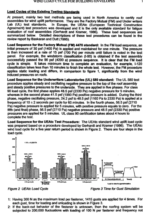
UEAtJ; Load Cyclet: Having 300 N as the maximum load per fastener, 1415 gusts are applied for 4 times. For each gust. time for loading and unloading is shown in Figure 3.
2: If the back-out behavior of the fastener is unknown, then the roofing system wiD be subjected to 200,000 fluctuationswithloading of 100 N per fastener and frequency not Load Cycles of the existing Testing Standard.
At present, mainly two test methods are being used in North America 10 certify roof assemblies for wind uplift performance. They are the Factory Mutual (FM) and Under writers lab (Ul) test standards. In Europe, the UEAtc (European Technical Construction Agreement) test procedure was developed anditis theonly available standardforfatigue evaluationof roof assemblies (Gerhardt and Kramer, 1986). Theseload sequences are summarized below. Detailed descriptionsof these test procedures
can
be found inthereview report by Baskaran and Duit (1995).
Load Sequence for the Factory Mutual (FM) 4470 standard: IntheFMloadsequence, an initial pressure of 30 pst (1400 Pal is applied and maintained for one minute. The pressure
isthen increased
at
a rateof15pst
(700 Pal per minute until failure is noted inthetest panel. For example, Ule windstorm classification HQセYPI is obtained if the test assemblysuccessfully passed the 90 psi (4200 aj pressure sequence.
tt
isclear
that theFM load
cycle is simple. It takes minimum time to compJete an evaluation, for example, 1-120 classification takesless than 10 minutes to finish thewholetest. However, theFM procedure applies staticloading and differs,. in comparison to figure 1, significantly from the wind induced pressures on roofs.
Load Sequence for the Underwriters laboratories
(Ul) 580
standard: The UL 580 test procedure applies sready -and oscUlating negative pressure to thetop of the roof assembly and steady positive pressures to the underside. They are applied in fivephases.For class90load cycle,the first phase applies 48.5 psf (2330Pa)negative pressure for 5 minutes,
whereas inthesecond phase41.5 psf (1990 Pal positive pressureisadded. Duringthethird phase, negative oscillating pressure, 24.2 psfto48.5psf (1160 Pa to 2330 Palis applied at a frequency of 10±2 seconds per cycle for60,minules. In the fourth phase, 56.5 psf (2710 Pal negative pressureis applied for 5 minutes, with positive pressure equals to zero. For the
fifth(and final) phase, 56.5 pst (2710 Pal negative pressure and 48.5 psf {2330 Pal positive
pressures are applied for 5 minutes. Ul class 90 certification takes about 4 hours to comptete the test.
Load Sequence for the UEAtc Test Procedure: The UEAtc standard wind uplift load cycle was prepared based on a procedure developed by Gerhardt and Kramer (1986). The UEA!:c wind load cycle for a fIVe year retum period is shown in Figure 2. There are four
steps
intheload
cycle. SuctionPre... ( p. )
/
Internal Posttlv.
Pressure (PI)
AbstractWind induced pressures on commercial building envelopes are dynamic. Existing evaluation protocols are limited
to
static conditions. Througha
North American roofing c::msortium, theSpecIalInterest Groupfor,Dynamic EvaluaUon ot Roofing Systems -SlGDERS, the National ResearchCoonan of Canada Is developing a test standard for evaluating roofing systems under dynamic conditions.this
paper presents results from this on going research effort.Problem Definition: Building envelopes are designed to separate the controlled Indoor environme:1t from the outdoor en...1mnment. The building envelope consists of walls, a roof, 'A'indows and a basement. By taking the roofing systems as an example, this paper
presents
the development of a load cycle for wind performance evaluation. Similar procedures can also beapplied tor evaluating walls and windows against. wind effects. Wind flow over a typical roofing $)'Stem Isshownschematically in Figure 1. Ills clear that the wind-induced pressure will varywill
respect to time, as well as spatially over the roof. Figure 1 alsoshowsa typical pressure fluctuation on the roof obtained from a wind tunnel test. It Is obvious that the response of the roofing system Is also dynamic (Baskaran andDutt.
1995).A. Baskaran, Y.Chen and M.G. savage1
Development of a
Wind
LoadCycle
for Testingセュュ・イ」ャ。ャ Building EnvelopesFigure1 Wind Induced Pressure andFluctuations OveraRoof Assembly
INational Research Council Canada, Ottawa, Ontario, Canada K1A OR6. [email protected] 6
9
10 '5
WIndSl>8fl<lat Rool
_17I'.
(rnIs)WIND LOAD CYCLE FOR BUILDING ENVELOPES
Figure5NumberofCycles Vs Threshold Figure6.NumberofCycles Vs Wind Speed Load sequencedevelopment: Awind load sequence based on the wind tunnel
test
usingtheRFC is presented in Figure7. It shouldbe !)oted thatthisreflectsthe
on
going researchat
NRC rather than documenting a finalized product from the investigation. Roof surfaces can be divided into three regions. namely, comer, edge and field regions. In this presentation, sixteen taps in the comer region (taps 1, 2, 3, 4, 7. 8, 9,10, 13, 14 15, 16, 19, 20,21, and 22 - ref Figure 4) were usedto
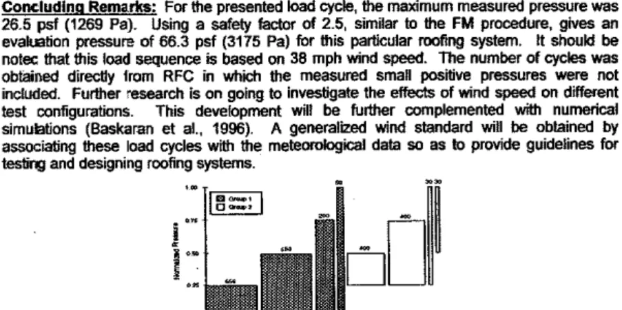
develop the load sequence. The numberセ load cyclesfor each pressure range was chosen fromthemaximumセ。ャオ・ .from these sixteen taps. Figure 7 shows the proposed wind loadセオセョ」・ for roof heightセョ、 speedofセW mls (38 mph) and the worst values from two wind directionsセョッイュ。ャ and ob.llQue) are considered. The load sequence is divided into two groups; one with a zero statIC mean value and a second group in which the cycles are applied over a constant static component. Group 1 can be viewed as wind induced suction over the roofassembly. Group 2 may reflect the combined exterior fluctuations and a constant interior pressureon
a building. Nevertheless, further data analyses are needed to confirm groupingsofthis nature. Each group canbefurther subdivided into fourload sequences as shown in Figure 7. Numberofcycles counted foreachload sequence is also presented on the figure.
To compute theloadcycle hom a wind pressure time history, the Rain Flow Count (RFC) method was employed. RFC is a process used to countloadcycles in a random process (Oowfing, 1976). Counted cycles can also be used to examine the cumulative、。ュ。ァセL
whicheventually produces fatigue failures, causedby the random loading sequence. RFClS
superior
to
other methods when the processisa broad-band and non-Gaussian random process, which isthe case for the wind induced pressure fluctuations on roofs of low buildings (Xu.1995).Effect of threshold onthetotal number of load cycles:When applying RFC, a threshold
is used
to
eliminate sman fluctuations, which will have littleeffecton
the fatigue. Forthepresent study, thresholds are calculated as percentage tothemaximum pressure. Figure
5
shows the relationship between thethresholds and total number of load cycles, fortwo
pressure taps. As shown in Figure 4, pressure tap7
isclosetothe comer and the tap 41 is near the middle of theroof. These results were obtained for a 450wind directionwith
roof
wind speed of 11.4mls(25.5mph). FromFIgUre 5,It can beseenthat the total numberof
cycles reduces as the threshold increases. The appropriate threshold for fatigue design consideration is also depends
on
thepropertyof roofing materials. However,in
this present study.5%of the maximum pressure has beenselectedas the threshold.Effect of wind speedon thetotalnumberof load cycles:Theincreasein wind speed will
cause an increase in the wind-induced pressure on the roof, thereby increasing the total numberofcycles, as shown in Figure6. These
two
curves represent two pressure taps (same as above)with450wind direction at different tested wind speeds. There is a linearrelationship between total number of cycles and wind speed. This can facilitate exbapolation
ofdata for wind speedsthat
are
nottestedinthewindtunnel.•
u .. I-
."
...
-
.-
r.-
.-
."
J
.
.- .-
.-
.-
y.-
.-セ
...
r.
-
L ..-
.-a
-
.-
<:'...-.-
.-
r.-
.-=.
:"...
.
-
.-
.-
.-
.-0" r
.-
,.
0-.-
セ::
.-
Zセ .-BUILDING TO LAST''If-wnd
(45")LセiサOオイ・ 4 Wind Tunnel Roof Assembly and Pressure Tap Distribution
exceeding10 Hz. This Isknown as conditioning cycle andItIsapplied betweenthirdand fourth loading.
3: Having 400 N8$the maximum load per fastener, 1415 gusts are applied once. 4: Increase the maximum load per fastener In the Increment of 100 Nandcontinue 1415
gusts until failure ls noticed.
The UEAtc load cycle Is designed for fatigue evaluation of roofing systems anditIs the only
standard available to the roofing Industry for such Investigations. The main difference
between the UEAtc loading and other (FMand Ul)Is that the UEAtc provides the fastener design load where others certify system for specified design pressure. However. the North
American roofing community has Indicated that the UEAtc procedure Is time consuming
(Smith, 1996). For example, to simulate the first 1415 gusts takes about 3 hours. This
Indicates that a lypl·21 testingwilltake more than one
day.
Also. the developed correlationbetween the measured load per fasteneranddesign pressures for the roofing assembly needs further consideration.
Other Test Procedures: Smith (1992) developed a fatigue test procedure to test ュ・」ィ。ョゥ」。ャセ at'::ached single ply membranes. The number of loading cycles
was
associated with wind speed Increment, using the Weibull probability distribution. letchford and Norville(1993)proposed a load sequence based on wind pressure records from the Texas Tech university Wind Engineering Research Field Laboratory. They used level crossing ar:d mean-range count analysis
as
the cycle counting methods. This load sequenceセウ further applied In the development of-Test Standard For Detetmining Impact Resistance From lM'ndbome DebriS'for the saccI (1994).National Research Council
of
canada's <NRC) Approach: Wind induced pressures on roofs and tt,9 roofing system responses to such pressures are dynamic. The existing test methodsdonot provide a satisfactory approach to this dynamicprocess.
The ongoing NRC research pr(lject alms to provide a detailed Investigation into the problem and develop a North Amer',can wind standard that will take Into consideration the dynamic nature of the wind load.tn
this paper a preliminary dynamic load sequence, developed based on the wind tunnel pressurerecord,is presented. It is applicable for testing mechanically-fastened Single Ply Foofing ISPR) systems. The wind tunnel tests were carried out In the9mx
9m NRC wind tunnel. These tests used full scale roofing components (3x
3m In size) at different hei';;Ihts forwinddirections perpendicular to a building face (normal wind) and at 45 degrees to a face (oblique wind). A PVC roofing system was tested with 81 pressuretapsfitted In the single ply membrane (Figure4)tomeasure the unsteady pressure loads on the roof (Savage
at
at. 1996). Measurements were made In smooth wind and turbulent wind conditions for five wind speeds, ranging from 30 to 60 mph (13.4 mls to 26.8mls). In total, 30 configurations were tested. This paper summarizesthesetest results with module height of 1.37 m.Coneludlng Remarks: For the presentedloadcycle, the maximum measured pressure was
26.5
pst
(1269 Pal. Using a safetyfactor of
2.5, similarto
the FM procedure, gives an evaluation pressure of66.3 psf(3175Pa)for this particular roofing system. Itshouldbeoatec that this load sequenceis based on 38 mph wind speed. The number of cycles was
obtained directly 1ram RFC in which the measured small positive pressures were not included. Further research is on goingto investigate theeffectsof windspeedon different test configurations. This development will be further complemented wiU1 numerical simulations (Baskaran et at, 1996). A generalized wind standard will be obtained by
associating these load cycles with the meteorological data so astoprovide guidelinesfor
testingand designing roofing systems.
Figure7Preliminary NRC Load sequenceforDynamic Evaluation
Ref&renees
Baskaran. A. andDutt,0, 1995.セaーーャゥ」。エゥッョ of Lab Proceduresforthe Dynamic Evaluation
of Roofing Systems. Part 1: Review of Existingsセョ、。イ、ウセ IIReInternal Report No; 692.
Baskaran.
A.;
Kas1E!f, Aand Savage, M.G, 1996. 'Wind Performance Evaluation of Roofing Systems Using Numerical Models" Submittedto:
J
of Wind Engr. Industrial Aerodynamicspp.l-33.
Dewing, N.E., 1976. "Fatigue Failure Predictions for Complicated Stress..strain Histories·, Journal of Material, Vol. 7, No.1, pp.71-87.
Gerhardt, H.J. and Kramer, C., 1986. "Wind Induced Loading Cycle and Fatigue Testing of LightNeight Roofir:g Fixations·,J of Wind Engrg. Industrial Aerodynamics, Vol. 23,
pp.237-247.
Letchford, C.W. a,d Norville, H.S., 1993. "Wind Induced Pressure Loading Cycles for Wall Clad::ling· During Hurricanes·, Glass Research and Testing Laboratory, Texas Tech UnilF.!rsity, Lubbock,TX, USA
SBCCI, 1994. "SBCC! Test StandardForDetennining Impact Resistance From Wmdbome
Debris". SSTD 12-94.
savage, M.G, Ba;;karan, A, Cooper,KR and Lei,W., 1996. MPressure Distribution Data Measured During the November1994Wind Tunnel Tests on a Mechanically-Attached,PVC
Single-Ply Roofirl{;' System·,IARReport LTR-A-Q03, National Research Council, Canada..
Smill. Phillip J., 1992. "Testing Methods for Roof Systems·, ASCE symposium on the
Hurricanes of 1992, pp.340-349.
Smitl. T. L, 1996 Personal Communication.
Xu.Y.L., Mehta,K.C. and Reardon, G.F., 1995. "Fatigue of Metal Roof Cladding Subject to
Wind Loading. Part I: Fatigue-Related Characteristics of Roof Pressures", Proceedings of 91CWE,NewDelhi, India, pp.1067-1078.
Acknowledgment: The presented research is being carried out for a consortium,Special Interest Group for Dynamic Evaluation of RoofIng Systems - SIGDERS,which consists of manufacturers (Canadian General Tower ltd., Prospex Roofing Products Ltd, Carlisle SynTec Systems, Cemfort Inc., Firestone Building Products Co.,JPSElastomerics Corp., Construction Products Group, Soprema Canada, VJCWestSteel),buildingowners(Canada
PoslCorporation, Department of National Defense, Public Works and Government Services Canada and associations (Canadian Roofing Contractors' Association and National Roofing Contractors' Association).