HAL Id: hal-00232621
https://hal.archives-ouvertes.fr/hal-00232621
Submitted on 1 Feb 2008
HAL is a multi-disciplinary open access
archive for the deposit and dissemination of
sci-entific research documents, whether they are
pub-lished or not. The documents may come from
teaching and research institutions in France or
abroad, or from public or private research centers.
L’archive ouverte pluridisciplinaire HAL, est
destinée au dépôt et à la diffusion de documents
scientifiques de niveau recherche, publiés ou non,
émanant des établissements d’enseignement et de
recherche français ou étrangers, des laboratoires
publics ou privés.
A Hardware Projector/Backprojector Pair for 3D PET
Reconstruction
Nicolas Gac, Stéphane Mancini, Michel Desvignes, Florian de Boissieu,
Anthonin Reilhac
To cite this version:
Nicolas Gac, Stéphane Mancini, Michel Desvignes, Florian de Boissieu, Anthonin Reilhac. A Hardware
Projector/Backprojector Pair for 3D PET Reconstruction. SPIE Medical Imaging, Feb 2008, San
Diego, Californie, United States. pp.69132O, �10.1117/12.770588�. �hal-00232621�
A Hardware Projector/Backprojector Pair for 3D PET
Reconstruction
Nicolas Gac
a, St´ephane Mancini
a, Michel Desvignes
a, Florian Deboissieu
aand Anthonin
Reilhac
ba
Gipsa-lab, INPG-CNRS, 46 avenue F´elix Viallet, 38031 Grenoble, France
bCERMEP, 59, Boulevard Pinel, 69003 Lyon, France
ABSTRACT
Forward and Backward projections are two computational costly steps in tomography image reconstruction such as Positron Emission Tomography (PET). To speed-up reconstruction time, a hardware projection/backprojection pair has been built following algorithm architecture adequacy principles. Thanks to an original memory access strategy based on an 3D adaptive and predictive memory cache, the external memory wall has been overcome. Thus, for both projector architectures several units run efficiently. Each unit reaches a computational throughput close to 1 operation per cycle.
In this paper, we present how from our hardware projection/backprojection pair, an analytic (3D-RP) and an iterative (3D-EM) reconstruction algorithms can be implemented on a System on Programmable Chip (SoPC). First, an hardware/software partitioning is done based on the different steps of each algorithm. Then the reconstruction system is composed of two hardware configurations of the programmable logic resources (FPGA). Each one corresponds mainly to the projection and backprojection step.
Our projector/backprojector has been validated with a software 3D-RP and 3D-EM reconstruction on sim-ulated PET-SORTEO data. A reconstruction time evaluation of these reconstruction systems are done based on the measured performances of our projectors IPs and the estimated performances of the additional simple hardware IPs. The expected reconstruction time is compared with the software tomography distribution STIR. A speed-up of 7 can be expected for the 3D-RP algorithm and a speed-up of 3.5 for the 3D-EM algorithm. For both algorithms, the architecture cycle efficiency expected is largely greater than the software implementation : 120 times for 3D-RP and 60 times for 3D-EM.
Keywords: Positron Emission Tomography, Iterative reconstruction, Backprojection, Projection , FPGA
1. INTRODUCTION
Reconstruction of images in tomography is cpu intensive and usually postponed. There are several imple-mentations of reconstruction systems to speed up its computation : PC clusters1, 2 , DSP3 , multi-processor
machines4–6, Cell7, 8, GPU9or FPGA10–12. All these implementations have to face the memory bottleneck due
to the limited bandwidth of the main memory. Our projector and backprojector IPs reach an efficient computing throughput. Indeed, this projector/backprojector hardware pair overcomes the memory access bottleneck thanks to a prefetching memory strategy.
In this paper, we use a projection/backprojection pair both for analytic and iterative reconstruction algo-rithms. On one hand, the 3D-RP algorithm defines explicitly the projection and the backprojection as geometric
Further author information: N. Gac : E-mail: [email protected]
S. Mancini : E-mail: [email protected], Telephone: + 33 4 76 57 43 58 M. Desvignes : E-mail: [email protected], Telephone: + 33 4 76 82 64 21 A. Reilhac : E-mail: [email protected], Telephone: + 33 4 72 68 86 13
projectors which correspond to our hardware IPs. On the other hand, the 3D-EM algorithm defines the pro-jection and backpropro-jection steps as a matrix multiplication. Because this matrix is defined by the number of bins (number of events into one detector) and the number of voxels, its size is too huge to be stored without factorisations, compressions or approximations13. Our study will be focused on the geometric matrix system in
which each element (i,j) corresponds to the probability that a photon pair produced in voxel j is detected on the captor i.
The projection and backprojection steps in iterative algorithms can be done either through a computation on the fly of the matrix system by efficient geometric operators, or thanks to a compressed system matrix built beforehand. In this latter case, the system matrix is computed by analytic pre-computation14 , Monte
Carlo simulations15 or experimental measurements16. Moreover, not only sparsity and symmetry are exploited
in order to get a reasonable matrix size, but also compression techniques with loss14 . When system matrix
is compute on the fly, the standard manner is to use a projection/backprojection pair made of a ray driven projector and a bi-linear voxel driven backprojector. This unmatched pair is known to be a convergent solution for EM algorithms17.
2. ALGORITHMS
2.1 3D-RP
The 3D ReProjection (3D-RP)18algorithm computes a first estimation of the volume by a 2D Filtered
BackPro-jection (FBP2D) made of a 2D Ramp Filtering step Frfollowed by a 2D backprojection BP2D. Afterwards, a 3D
Forward Projection FP3Dof the estimated volume is proceeded in order to complete the projection data. Finally
the volume is reconstructed through a 3D Filtered Backprojection (FBP3D) made of a 3D Colsher Filtering step Fcfollowed by a 3D backprojection BP3D.
2.2 3D-EM
The Expectation Maximisation algorithm applied to Emission Tomography19, 20 is an iterative technique for
computing the maximum likelihood estimates of the activity density f from the measured data g. The acquisition system is modelized by the matrix system H = (hij). At each iteration step, a new volume estimation ˆf(n+1)is
computed from the last volume estimation ˆf(n)as described below :
ˆ fj(n+1)= ˆ fj(n) ! i!hi!j " i hij gi ! khikfˆk(n) (1) (FP3D) 3D Forward Projection of ˆf(n) : ˆg(n)i = " k hikfˆk(n).
(SC) Sinogram Comparison between the measured data giand the estimated data ˆg(n) : !(n)i =
gi
ˆg(n) i
.
(BP3D) 3D Back Projection of the correction data !(n)i : BP (n) j =
"
i
hij!(n)i .
(BN) Backprojection Normalisation with application of the sensibility image sj to the backprojected image
BP(n) : C(n) j = 1 ! i!hij · BP (n) j = 1 sj · BP (n) j .
(IC) Image Correction with the application of the correction image C(n) to ˆf(n) : ˆf(n+1) j = ˆf
(n) j · C
(n) j .
3. A HARDWARE PROJECTOR/BACKPROJECTOR PAIR
3.1 Backprojector IP
The 3PA-PET21 Backprojector is a 3P Architecture for PET : Pipelined, Prefetched and Parallelised. The
exploitation of the intrinsic temporal and spatial locality by the 3D Predictive and Adaptive (3D-AP) memory cache succeeds to run efficiently several pipelines of backprojection : each reaches a computational throughput close to 1 operation per cycle. One backprojection unit is illustrated on figure 1 and the parallelized architecture on figure 2. DATA ADDRESS DATA SRAM Cache 1 cycle Latency (10−100 Ko) SoPC : System on Programmable Chip COORDINATE 3D−AP 4−10 cyclesLatency (128 Mo−1 Go) 3DRP SDRAM ACCES TIME
LAMBDA (PLANE NUMBER)
PSI (ANGLE NUMBER)
RHO (BIN NUMBER)
Figure 1. A backprojector unit is composed of a 3D backprojection operator joined with a 3D-AP cache. The memory access strategy is based on a fast and small cache memory inside the SoPC. It predicts the needs of the 3D Back-Projection which draws a 3D sinusoid into the 3D memory space of the projection data. Therefore the cache succeeds to mask the 4-10 cycles latency of the slower and bigger external SDRAM memory.
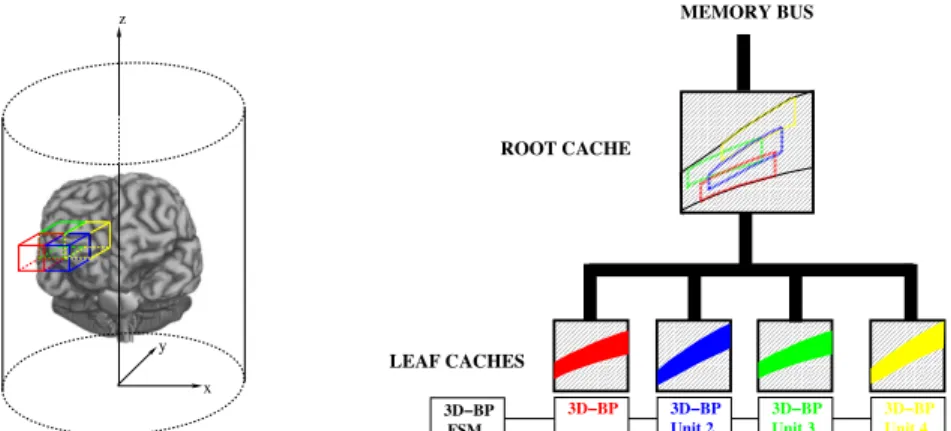
LEAF CACHES 3D−BP Unit 1 FSM y x z 3D−BP 3D−BP 3D−BP Unit 3 Unit 2 MEMORY BUS ROOT CACHE Unit 4 3D−BP
Figure 2. The backprojector architecture is composed of several operators of 3D backprojection joined with its 3D-AP cache. Each backprojection unit is assigned to the reconstruction of one block of voxels. A hierarchical cache reduces as much as possible the memory bus occupation when backprojection units work in parallel.
3.2 Projector IP
The ray casting 3D projector IP22achieves a high computation throughput thanks to a synchronised ray casting
of LORs drawing close paths in the volume. This temporal and spatial locality in the volume accesses allows an efficient use of the hierarchical 3D adaptive and predictable cache.
4. TOWARDS A HARDWARE/SOFTWARE RECONSTRUCTION
4.1 A Hardware/Software Architecture on a SoPC
The reconstruction system uses a board with a System on Programmable Chip (SoPC) connected to a PC host. The SoPC technology solution is a middle way between a completely software or hardware (ASIC) implementa-tion. Thanks to its programmable logic resources (FPGA) a dedicated architecture can be implemented. This architecture can be seen as a co-processor integrated in a classical system with an embedded processor and memory. In this way, a hardware/software partitioning can be done on the chip according to the computation steps. Moreover, the PC processor can be used as an additional computation resource.
4.2 3D-RP Reconstruction
The filtering steps (Fr and Fc) are done on the PC host processor whereas the projection and backprojection
steps are done on the SoPC board. The projector (F P3D) defines a hardware configuration of the SoPC board
and the backprojector (BP2D and BP3D) another one. To compute a 3D-RP reconstruction, we will need to
configure one chip as a backprojector for BP2Dand BP3D, and another one will be configured as a projector for
the F P3Dstep.
4.3 3D-EM Reconstruction
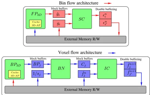
As illustred on figure 3, the 3D-EM reconstruction system is mainly composed of two SoPCs : one for a bin flow architecture (FP3Dand SC) and another one for a voxel flow architecture (BP3D, BN and IC). This two
architectures are made of a chain of modules associated each one to a computation step. A buffer at the output of each hardware modules stores a block of proceeded data which are ready to be used by the next module.
These steps are done one after another because of the limited bandwidth of the external memory. The last module of the chain uses double buffering technique to compute a block of data and as the same time writes the previous block of data computed.
4.3.1 Bin Flow Architecture
This architecture is made of a 3D projector FP3D and a module for the SC step. This one is defined only as a
divider of bins which can be conceived with a computation throughput of one division per cycle. Therefore, the computing time of the SC step is limited mainly by the external memory access : one read access on a block of measured data giand one write access on a block of sinogram comparison !(n)i .
4.3.2 Voxel Flow Architecture
This architecture is made of a 3D backprojector BP3Dand two multipliers for the BN and IC steps. The
hard-wired multiplier on Virtex chip can be efficiently used to reach a computation throughput of one multiplication per cycle. As for the SC step, the BN and IC steps are limited mainly by the external memory access : one read access on a block of sensibility image voxels sjfor the BN step, one read access on a block of image voxels
ˆ
block buffers
block buffers
Voxel flow architecture
Bin flow architecture
Double buffering Double buffering block buffers External Memory R/W External Memory R/W !n i! BN IC SC ! n i ˆ fjn+1 ˆ fjn+1! BPj BP3D gi F P3D ˆgi Cj ˆ fn j 1/sj Cache Cache 3D-AP 3D-AP
Figure 3. 3D-EM Reconstruction uses a voxel flow architecture and a bin flow architecture.
5. QUALITY OF RECONSTRUCTION
5.1 A convergent projector/backprojector pair
Simulated brain study data provided by the Monte Carlo based PET simulator PET-SORTEO of A.Reilhac23
has been used as data set. A brain phantoms has been reconstructed with the software tomography distribution STIR version 2.024and with a software version of the 3D-RP and 3D-EM as well. The goal of this comparison is
to validate our projection/backprojection pair. STIR and our projection/backprojection pair are quite similar. STIR one is made of a ray tracing projector using a variation of Siddon’s algorithm25 and an incremental,
beamwise interpolating backprojector using Cho’s algorithm26, 27 . Original and reconstructred phantoms are
presented on figure 4.
On table 5.1, STIR and our software are compared through the Mean Absolute Percentage Error (MAPE) for analytic and iterative algorithms. For 3D-RP, STIR and our reconstructions are very close with only a MAPE of 0, 63%. For iterative reconstruction, we don’t use a regularization step as STIR OSMAPOSL does. As a matter of fact, the MAPE is higher and reaches 2.42% after 30 iterations. Nevertheless, this result proves that our projection/backprojection pair allows an acceptable 3D-EM convergence.
3D-RP(Gac et al)/3D-RP(STIR) 3D-EM(Gac et al)/OSMAPOSL(STIR)
MAPE 0.63% 2.42%
Table 1. Mean Absolute Percentage Error (MAPE) computed between STIR and our software for analytic and iterative algorithms.
5.2 Fixed/Floating point arithmetic
If the software backprojector used to validate the overall reconstruction uses a fixed point arithmetic as our hardware backprojector (FPGA technology doesn’t allow floating point arithmetic), it’s not the case for the software projector. As a consequence, the software projection/bacprojection pair is not a 100 % bit true version of the hardware pair. Thus the sudy above doesn’t reflect the exact quality of reconstruction that we can expected from the hardware pair. Nevertheless, we have observed on previous work21 that backprojection is quite robust
to noise computation. Indeed, between two software backprojectors, one using a fixed point arithmetic and the other one a floating point arithmetic, a MAPE of only 0, 13% is observed. And as projector and backprojector
(a)
(b1)
(b2)
(c1)
(c2)
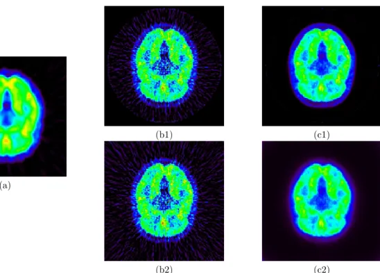
Figure 4. A numerical brain model associated with a FDG functional model is used by the Monte Carlo based PET simulator PET-SORTEO to generate simulated PET data. Above is presented : the original FDG emission phantom (a), the phantoms reconstructed by STIR 3D-RP (b1) and by our 3D-RP (b2), the phantoms reconstructed by STIR OSMAPOSL (c1) and our 3D-EM (c2) after 30 iterations.
use quite similar dynamic of computation, we can expect an equivalent robustness to computation noise. This means that the results presented on table 5.1 are not too far away from the quality of reconstruction that we can expect with our hardware projector/backprojector pair.
.
6. RECONSTRUCTION TIMES
6.1 Estimation
The SoPC time performance presented at this section are based on the measured performances of our projectors IPs21, 22 and the estimated performances of the additional hardware modules (only for the 3D-EM algorithm).
The computing time of our projectors IPs has been measured on a Virtex 2 Pro at 35 Mhz. From these measures, we get a reconstruction time in clock cycles per operation. As Virtex 2 Pro technology is an older generation than Pentium 4 one, we have scaled our Virtex 2 Pro results to a 200 MHz architecture that can be reasonably obtained on a Virtex 4 chip.
For 3D-RP (table 2) and 3D-EM (table 3), we compute for each step the processing time through the multiplication of the cycles per operation (Cycles/Op) times the number of operation per element (Nb Op/Elt) times the number of element (Nb Elt). For backprojection, an element corresponds to a reconstructed voxel and an operation to the accumulation of one bin to the reconstructed voxel. For forward projection, an element corresponds to a volume integration along a LOR and an operation to the computation of a line intersection between a LOR and a voxel. The projection data correspond to a Siemens HR+ scanner. They are made of 239 + 162 = 401 sinograms for 3D-RP and of 239 sinograms for 3D-EM. The volume is made of 128 ∗ 128 ∗ 63 voxels.
A 3D backprojector with 8 units can be put on a Virtex 4 FX60 and a 3D projector with 8 units on another one. With these 8 units 2D/3D backprojection and 3D forward projection reach respectively a computational throughput of about 0,25 cycles per operation and 0,5 cycles per operation. To the total reconstruction time an overhead of 20 % has been added corresponding to the communication cost between each step.
Elt Nb Elt Nb Op/Elt Cycles/Op (Unit) Time (BP2D) 2D Back Projection Voxels 1 · 106 144 0.25 (8) ∼ 185 ms
(F P3D) 3D Forward Projection LORs 6, 3 · 106 ∼ 200 0.5 (8) ∼ 3.2 s
(BP3D) 3D Back Projection Voxels 1 · 106 144 · 5 = 720 0.25 (8) ∼ 930 ms
TOTAL without filtering ∼ 4.3 s + 20% overhead = 5.2 s
Table 2. Evaluation of the reconstruction time and cycle efficiency of our reconstruction system for the 3D-RP Algorithm without the filtering steps
Elt Nb Elt Nb Op/Elt Cycles/Op (Unit) Time/Iteration (F P3D) 3D Forward Projection LORs 9.3 · 106 ∼ 200 0.5 (8) ∼ 4.65 s
(SC) Sinogram Correction LORs 9.3 · 106 1 1.25 (1) ∼ 70 ms
(BP3D) 3D Back Projection Voxels 1 · 106 720 0.25 (8) ∼ 930 ms
(BN) BP Normalization Voxels 1 · 106 1 1.25 (1) ∼ 10 ms
(IC) Image Correction Voxels 1 · 106 1 1.25 (1) ∼ 10 ms
TOTAL ∼ 5.7s + 20 % overhead = 6.8 s
Table 3. Evaluation of the reconstruction time and cycle efficiency of our reconstruction system for one iteration of the 3D-EM algorithm
6.2 Comparison with STIR
We have compared the expected reconstruction time of our SoPC system with STIR reconstruction time measured on a Pentium 4 for 3D-RP and 3D-EM, respectively on table 4 and table 5. A 128∗128∗63 volume is reconstruted by our reconstruction systems but as STIR reconstructs a cylindrical volume with 64 ∗ 64 ∗ Π ∗ 63 voxels, we scaled STIR reconstruction time to a 128 ∗ 128 ∗ 63 volume.
Algorithm Hardware Time FP/BP Cycles/Voxels FBP3D (STIR) Pentium 4 (3.2 GHz) 38.6 s 49%/50% 120 000 FBP3D Virtex 4 (200 MHz) ∼ 5.2 s 74%/25% ∼ 1 000
Table 4. Reconstruction time and cycle efficiency measured for the software 3D-RP STIR reconstruction done on a Pentium 4 and expected on our reconstruction system. This reconstruction times are evaluated without the filtering steps.
Algorithm Hardware Time FP/BP Cycles/Voxels OSMAPOSL (STIR) Pentium 4 (3.2 GHz) 24.6 s / Iteration 54%/45% 76 300 EM Virtex 4 (200 MHz) ∼ 6.8 s/ Iteration 82%/16% ∼ 1 320
Table 5. Reconstruction time and cycle efficiency measured for the software OSMAPOSL STIR reconstruction done on a Pentium 4 and expected on our reconstruction system.
6.3 Discussion
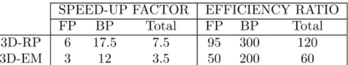
As presented on table 6, a speed-up of 7.5 can be expected for 3D-RP and 3.5 for 3D-EM. Moreover, one can observed that speed up factors achieved by the backprojector is better than the forward projector for both reconstruction algorithms (3D-RP and 3D-EM). This can be explained by the greater complexity of the 3D projector to be efficiently parallelised. Indeed, throwing of LORs have to be synchronised to keep a good
temporal and spatial locality when passing through the whole volume. Moreover STIR takes advantage of the exploitation of symmetries to reduce the number of rays thrown which is not the case for our current projector. Because STIR backprojection is ray-driven and as the number of LORs is less for 3D-EM, its number of operation is less. As a consequence, speed-up factor of our backprojector compared with STIR one, is less for 3D-EM (12) than for 3D-RP (17.5). The better efficiency of STIR projector for 3D-EM compared with 3D-RP is due to the exploitation of the axial symmetry more important in the projection data for 3D-EM. For all these reasons, speed up factor is twice less for 3D-EM (3.5) than for 3D-RP (7). For the same reasons, the 3D-RP efficiency ratio (120) which is the ratio between our Cycles/Voxels efficiency and STIR one’s, is higher than 3D-EM ratio (60).
SPEED-UP FACTOR EFFICIENCY RATIO FP BP Total FP BP Total 3D-RP 6 17.5 7.5 95 300 120 3D-EM 3 12 3.5 50 200 60
Table 6. Speed up factors and Efficiency ratio between our reconstruction system and STIR software implementation.
7. CONCLUSION
An analytic and iterative 3D PET reconstruction system, integrating a hardware projection/backprojection pair has been described. Thanks to an architecture algorithm adequacy methodology, 3D projection and 2D/3D backprojection reach an efficient computing throughput. For both 3D-RP and 3D-EM algorithm, 3D backpro-jection is accelerated by an order of magnitude and 3D probackpro-jection remains the main computational costly steps. Improvements can be reached with a special effort on the 3D projector conception. For instance, exploitation of the LORs symmetries as STIR projector does, can give a better speed up factor. In comparison with the software implementations of STIR, an acceleration of 7 for 3D-RP and 3.5 for 3D-EM can be expected. The reconstruction system presents a notably better cycle efficiency which let’s hope better speed up factor with higher system frequencies on the next FPGA generations or on an ASIC implementation.
REFERENCES
1. G. Kontaxakis, “Iterative image reconstruction for clinical PET using ordered subsets median root prior and web-based interface,” Mol. Imaging Biol. 4, pp. 219–233, May 2002.
2. S. Vollmar, C. Michel, J. Treffert, D. Newport, M. Casey, C. Knoss, K.Wienhard, X. Liu, M.Defrise, and W.-D. Heiss, “Heinzelcluster accelerated reconstruction for FORE and OSEM3D,” Phys. Med. Biol. 47, pp. 2651–2658, Aug. 2002.
3. K. Rajan and L. Patnaik, “Cbp and art image reconstruction algorithms on media and dsp processors,” Microprocessors and Microsystems 25(5), pp. 233–238, 2001.
4. D. Keesing, J. O’Sullivan, D. Politte, and B. Whiting, “Parallelization of a fully 3d ct iterative reconstruc-tion,” in Biomedical Imaging: Macro to Nano, 2006. 3rd IEEE International Symposium on, pp. 1240–1243, 6-9 April 2006.
5. M. Schellmann, T. Kosters, and S. Gorlatch, “Parallelization and runtime prediction of the listmode osem algorithm for 3d pet reconstruction,” in Nuclear Science Symposium Conference Record, 2006. IEEE, 4, pp. 2190–2195, Oct. 2006.
6. J. S. Kole and F. J. Beekman, “Parallel statistical image reconstruction for cone-beam x-ray ct on a shared memory computation platform,” Physics in Medicine and Biology 50(6), pp. 1265–1272, 2005.
7. M. Kachelriess, M. Knaup, and O. Bockenbach., “Hyperfast perspective cone-beam backprojection,” in IEEE Medical Imaging Conference Record, 2006.
8. M. Sakamoto, H.Nishiyama, H.Satoh, S.Shimizu, T. Sanuki, K.Kamijoh, A. Watanabe, and A. Asahara, “An implementation of the feldkamp algorithm for medical imaging on cell,” tech. rep., IBM, 2005. 9. K. Mueller, F. Xu, and N. Neophytou, “Why do commodity graphics hardware boards (gpus) work so well
10. N. Sorokin, An FPGA-Based 3D Backprojector. PhD thesis, Universitt des Saarlandes, Allemagne, 2003. 11. J. Li, C. Papachristou, and R. Shekhar, “A reconfigurable Soc architecture and caching scheme for 3D
medi-cal image processing,” in Proc. IEEE Symp. Field-Programmable Custom Computing Machines (FCCM’04), (Napa, USA), Apr. 2004.
12. M. Leeser, S. Coric, E. Miller, H. Yu, and M. Trepanier, “Parallel-beam backprojection: an fpga implemen-tation optimized for medical imaging,” J. VLSI Signal Process. Syst. 39(3), pp. 295–311, 2005.
13. J. Qi and R. L. et al, “Fully 3d bayesian image reconstruction for the ecat exact hr+,” IEEE Tr. Nucl. Sci. 45, pp. 1096–1103, June 1998.
14. J. Scheins, F. Boschen, and H. Herzog, “Analytical calculation of volumes-of-intersection for iterative, fully 3-d pet reconstruction,” Medical Imaging, IEEE Transactions on 25, pp. 1363–1369, Oct. 2006.
15. J. L. Herraiz, S. Espa˜na, J. J. Vaquero, M. Desco, and J. M. Ud´ıas, “FIRST: Fast Iterative Reconstruction Software for (PET) tomography,” Physics in Medicine and Biology 51, pp. 4547–4565, Sept. 2006. 16. V. Panin, F. Kehren, C. Michel, and M. Casey, “Fully 3-d pet reconstruction with system matrix derived
from point source measurements,” Medical Imaging, IEEE Transactions on 25, pp. 907–921, July 2006. 17. G. Zeng and G. Gullberg, “Unmatched projector/backprojector pairs in an iterative reconstruction
algo-rithm,” Medical Imaging, IEEE Transactions on 19, pp. 548–555, May 2000.
18. P. Kinahan and J. Rogers, “Analytic 3D image reconstruction using all detected events,” IEEE Tr. Nucl. Sci. 36, pp. 964–968, Feb. 1989.
19. L. Shepp and Y. Vardi, “Maximum likelihood reconstruction for emission tomography,” IEEE Tr. Med. Imaging 1, pp. 113–122, Oct. 1982.
20. K. Lange and R. Carson, “EM reconstruction algorithms for emission and transmission tomography,” J. Comput. Assist. Tomogr. 8, pp. 306–316, Apr. 1984.
21. N. Gac, S. Mancini, M. Desvignes, and D. Houzet, “Algorithm architecture adequacy for high speed 3d tomography,” in Workshop on Design and Architectures for Signal and Image Processing, Grenoble, France, November 2007.
22. S. Mancini and M. Desvignes, “Ray casting on a sopc : Algorithm and memory hierarchy trade-off.,” in Sixth International Conference on Computer and Information Technology (CIT 2006), 20-22 September 2006, Seoul, Korea, p. 180, 2006.
23. A. Reilhac, G. Batan, C. Michel, C. Grova, J. Tohka, D. Collins, N. Costes, and A. Evans, “Pet-sorteo: validation and development of database of simulated pet volumes,” Nuclear Science, IEEE Transactions on 52, pp. 1321–1328, Oct. 2005.
24. K. Thielemans, S. Mustafovic, and C. Tsoumpas, “Stir: Software for tomographic image reconstruction release 2,” in Nuclear Science Symposium Conference Record, 2006. IEEE, 4, pp. 2174–2176, Oct. 2006. 25. R. L. Siddon, “Fast calculation of the exact radiological path for a three-dimensional ct array.,” Med
Phys 12(2), pp. 252–255, 1985.
26. Z. Cho, C. Chen, and S. Lee, “Incremental algorithm-a new fast backprojection scheme for parallel beam geometries,” Medical Imaging, IEEE Transactions on 9, pp. 207–217, June 1990.
27. M. Egger, C. Joseph, and C. Morel, “Incremental beamwise backprojection using geometrical symmetries for 3d pet reconstruction in a cylindrical scanner geometry,” Physics in Medicine and Biology 43, pp. 3009–3024, Oct. 1998.