HAL Id: in2p3-00854119
http://hal.in2p3.fr/in2p3-00854119
Submitted on 23 Apr 2018
HAL is a multi-disciplinary open access
archive for the deposit and dissemination of
sci-entific research documents, whether they are
pub-lished or not. The documents may come from
teaching and research institutions in France or
abroad, or from public or private research centers.
L’archive ouverte pluridisciplinaire HAL, est
destinée au dépôt et à la diffusion de documents
scientifiques de niveau recherche, publiés ou non,
émanant des établissements d’enseignement et de
recherche français ou étrangers, des laboratoires
publics ou privés.
Microstructure of Cs-implanted zirconia: Role of
temperature
L. Vincent, L. Thome, F. Garrido, O. Kaitasov, Florent Houdellier
To cite this version:
L. Vincent, L. Thome, F. Garrido, O. Kaitasov, Florent Houdellier. Microstructure of Cs-implanted
zirconia: Role of temperature. Journal of Applied Physics, American Institute of Physics, 2008, 104
(11), pp.114904. �10.1063/1.3021162�. �in2p3-00854119�
Microstructure of Cs-implanted zirconia: Role of temperature
L. Vincent, L. Thomé, F. Garrido, O. Kaitasov, and F. HoudelierCitation: Journal of Applied Physics 104, 114904 (2008); doi: 10.1063/1.3021162 View online: https://doi.org/10.1063/1.3021162
View Table of Contents: http://aip.scitation.org/toc/jap/104/11 Published by the American Institute of Physics
Microstructure of Cs-implanted zirconia: Role of temperature
L. Vincent,1,a兲L. Thomé,1F. Garrido,1O. Kaitasov,1and F. Houdelier2 1
CSNSM-UMR8609, CNRS-IN2P3-Université Paris-Sud, F-91405 Orsay-Campus, France
2
CEMES-UPR8011, CNRS 29, rue Marvig BP 94347, 31055 Toulouse Cedex 4, France
共Received 1 July 2008; accepted 3 October 2008; published online 4 December 2008兲
The aim of this study was to identify experimentally the phase which includes cesium in yttria stabilized zirconia 共YSZ兲. The solubility and retention of cesium in YSZ were studied at high
temperature 共HT兲. Cesium was ion implanted 共at 300 keV兲 into YSZ at room temperature 共RT兲,
750 ° C, or 900 ° C at fluences up to 5⫻1016 cm−2. The temperature dependence of the
radiation-induced damage and of the cesium distribution in YSZ single crystals was investigated by Rutherford backscattering spectrometry and ion channeling. Transmission electron microscopy 共TEM兲 studies were performed in order to determine the damage nature and search for a predicted ternary phase of cesium zirconate. Whatever the implantation temperature, the thickness of the damaged layer increases inwards with ion fluence. At RT, amorphization occurs, caused by the high Cs concentration 共7 at. %兲. In situ TEM during postannealing shows recrystallization of cubic zirconia after release of cesium. A high implantation temperature has a significant influence on the nature of radiation defects and on the retained Cs concentration. At HT, dislocation loops and voids are formed but no amorphization is observed whereas polygonization occurs at high fluence. The implanted cesium concentration reaches a saturation value of 1.5 at. % above which Cs can no longer be retained in the matrix and is then released at the surface. At that concentration, cesium forms a solid solution in YSZ; no other phase is formed, neither during irradiation nor after thermal annealing. © 2008 American Institute of Physics.关DOI:10.1063/1.3021162兴
I. INTRODUCTION
Over the past decade, the concept of actinide destruction in inert matrix fuels共IMFs兲 has received increasing attention worldwide.1–3This approach allows a significant reduction of the Pu and minor actinide contents when using uranium-free fuel. Based on neutron irradiation-related and thermody-namic properties, numerous refractory ceramics have been selected for use as IMFs.4 Despite its low thermal conduc-tivity, yttria-stabilized cubic zirconia共YSZ兲 is considered to be one of the most promising IMFs5,6since it is chemically stable and may form solid solutions with high concentrations of actinide dioxides.7 Therefore, this advanced fuel is fore-seen as to be used in light water reactors and then directly sent to a final geological depository. Its exceptional radiation damage resistance under neutron irradiation8and low-energy ion bombardment9–11 has been demonstrated. YSZ does not undergo amorphization under heavy noble-gas implantation up to high displacement per atom共dpa兲 levels. Amorphiza-tion was only observed under Cs implantaAmorphiza-tion at room tem-perature共RT兲.12This structural transformation is more likely due to the chemical effect of incorporated Cs than resulting from atom displacements and was suggested by Wang et al.12 to be caused by the Cs+misfit in the YSZ structure due to its valence and its large ionic radius共165 pm兲 compared to the host atoms. The authors also emphasized the low mobility of Cs at RT.
Another crucial criterion to make use of YSZ as an IMF
and waste form is its ability to confine radiotoxic fission products in both of the potential utilization conditions, i.e., medium temperature for disposal and high temperature共HT兲 during burn up. This issue has only received little attention,13–18 especially regarding Cs retention at HT. The low thermal conductivity of YSZ implies that the IMF could reach very high operating temperatures共up to 1800 °C兲 in a reactor.19,20 Under such conditions, Cs diffusion, release, and/or precipitation are expected. Thus it is essential to study the solubility of Cs in YSZ at HT. In addition, the formation of cesium zirconate 共Cs2ZrO3兲 was predicted by several
authors.21,22Thermodynamic calculations performed by Pou-chon et al.14predicted the stability of this ternary phase up to 900 ° C, and the solubility limit of Cs 共up to 1700 °C兲 was estimated to be 1.5 at. %. From this relatively low solubility value, one can expect that Cs atoms may escape from the matrix or precipitate as cesium zirconate at HT.
The purpose of the present work was to determine ex-perimentally the phase in which Cs resides in YSZ at HT, i.e., as a solid solution or in cesium zirconate precipitates. For this purpose, ion implantation was used to incorporate Cs atoms in a YSZ matrix with related low-energy radiation
damage 共simulating damage created during reactor
opera-tion兲. In order to observe the possible formation of fission product precipitates and to determine the nature of the dam-age created by implantation, we combined transmission
elec-tron microscopy共TEM兲 experiments and in situ Rutherford
backscattering spectrometry in channeling mode共RBS/C兲 on YSZ single crystals implanted with Cs ions at various tem-peratures. The results presented here are organized in four sections. First, we summarize results on damage buildup in Cs-implanted YSZ at different temperatures. In the second
a兲Author to whom correspondence should be addressed. Electronic
mail: [email protected]. Tel.: ⫹33169155231. FAX: ⫹33169155268.
JOURNAL OF APPLIED PHYSICS 104, 114904共2008兲
and third sections, we discuss TEM results that provide in-formation on the nature and distribution of defects created at RT or at HT, viz., 750 and 900 ° C. Then we consider the retention of Cs in the matrix. Finally we discuss all our re-sults and conclude concerning the evolution of the damage and the solubility of Cs in YSZ.
II. EXPERIMENTAL
The specimens used in the present study are YSZ single crystals 共具100典 orientation兲 containing 9.5 mol % Y2O3, synthesized by Crystal-GmbH. All samples were coated with a conductive carbon layer 共thickness adapted to the charac-terization technique兲 in order to avoid charging under ion or electron beam irradiation.
Bulk samples were implanted with increasing fluences of
Cs ions at RT, 750 ° C, and 900 ° C. The ion flux was ⬃3
⫻1011 cm−2s−1. An incident beam angle of 7° was used to
avoid channeling. The Cs2+ion energy was 300 keV, leading to a projected range of about Rp= 67 nm and range
strag-gling approximately ⌬Rp= 25 nm. The depth distribution of
the implanted species and the number of dpa were estimated via the TRIM code23 assuming a displacement energy of 40 eV. TableIindicates共for each fluence兲 the dpa equivalent at the defects distribution maximum and the maximum Cs con-centration estimated fromTRIM.
RBS/C analyses were carried out in situ with the IRMA/
ARAMIS facility of CSNSM-Orsay.24 A two-axis
goniom-eter was specifically developed to allow HT implantation and RBS/C measurements. The temperature was measured by a thermocouple fixed on the sample holder. During implanta-tion, the temperature stability was better than 5 ° C. Fluences were incremented from 1014up to 5⫻1016 cm−2. After each
implantation step, RBS/C measurements were performed near RT with a 3.065 MeV He2+beam at a detection angle of
165°. The energy resolution of the electronic setup was 15 keV corresponding to a depth resolution better than 10 nm at the YSZ surface.
Several implanted samples were cut and thinned for plan
view and cross-section TEM 共XTEM兲 at 200 and 300 kV.
The thermal evolution of damage in RT preimplanted XTEM samples was studied in situ after successive isochronal 共15 min兲 anneals using a double tilt TEM hot stage from 300 to 750 ° C, and a final anneal was performed for 1 h at 750 ° C.
High resolution TEM 共HRTEM兲 was carried out using the
SACTEM-Toulouse, a Tecnai F20 ST 共FEI兲 fitted with an
imaging aberration corrector共CEOS兲, a 2000 charge-coupled
device camera共Gatan兲, and imaging filter 共Gatan Tridiem兲. In addition, the structural evolution as a function of the fluence was investigated in situ with a Philips CM12 trans-mission electron microscope on line with the IRMA ion implanter.25TEM samples were implanted at RT and 750 ° C with 70 keV Cs+ions共Rp= 20 nm and⌬Rp= 8 nm兲. Cs
flu-ences varied from 1014 up to 5⫻1015 cm−2. TRIM calcula-tions indicate that for the same Cs fluence, the number of dpa at the maximum of the defect distribution is about 30% lower at 70 keV than at the energy used for RBS/C in bulk samples共300 keV兲 共see Table I兲.
III. RESULTS
RBS/C was used for quantitative measurement of the lattice disorder and of the implanted Cs concentration. TEM observations provide qualitative complementary information on the damaged structure at the main steps of the damage kinetics. This approach was used to determine the influence of temperature on the nature of created defects and on Cs diffusion and/or precipitation. In the first subsection, we compare the damage buildup at different temperatures. Then we present results obtained on the structure of Cs-implanted YSZ at RT. Results are also given on the effect of a thermal post-anneal. In the third section, we focus on the nature of defects created by HT implantation. Finally, Cs depth pro-files are examined to determine Cs solubility in YSZ at HT.
A. Disorder buildup
From RBS/C spectra, one can obtain the impurity con-centration and the fractional lattice disorder共fD兲. The
meth-odology was described elsewhere.26Figure1shows the high-TABLE I. Implantation parameters and values of dpa and concentration
calculated byTRIMfor selected fluences of Cs. Energy 共keV兲 Fluence 共cm−2兲 dpa Cmax 共at. %兲 70 3⫻1014 0.9 0.2 300 3⫻1014 1.3 0.05 300 9⫻1014 3.8 0.16 300 5⫻1015 21 0.92 300 1016 43 1.84 300 5⫻1016 213 9.2
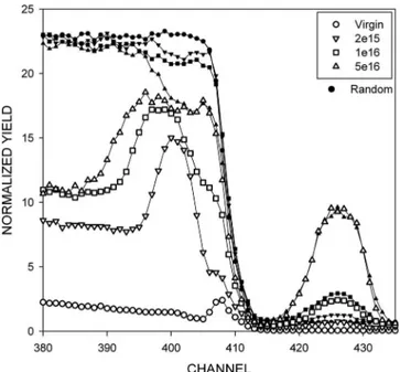
FIG. 1. High-energy part of RBS spectra recorded in random共filled sym-bols兲 and 具100典-axial 共open symbols兲 directions on YSZ crystals implanted with 300 keV Cs ions at RT. The Cs peaks are located around the channel 425. A background due to the presence of Hf impurities in YSZ is superim-posed to the Cs signal and is deconvoluted during analysis. Damage accu-mulation is noticeable on the axial spectra in the channel range关390–410兴. Depth profiles and kinetics of disorder yield are extracted from the analysis of these spectra.
energy part of typical RBS/C spectra recorded along the 具100典 axis on YSZ crystals implanted with increasing Cs ion fluences at RT. The analysis of the Cs peak around channel 425 provides the Cs depth distribution, as discussed in the last section below. In the YSZ near-surface section of the “random” spectra, the backscattering yield is reduced as the fluence increases due to the relative concentration increase in Cs in the matrix. The analysis of the damage peak between channel 390 and 410 gives the depth profiles of fDcreated in
the Zr sublattice of the crystal. This disorder increases with increasing fluence. Hence, we can follow the damage buildup which is the amount of damage共fDmax兲 accumulated at the maximum of the damage peak as a function of the fluence共or the dpa兲.
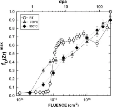
Figure2shows the plots of the damage buildup, for the three implantation temperatures RT, 750 ° C, and 900 ° C. At RT, the damage buildup clearly exhibits distinct stages:共1兲 a plateau characterized by a very low damage level,共2兲 a tran-sitional rise of the disorder level around 1015 ions cm−2 共4 dpa兲, 共3兲 a slowly rising plateau, 共4兲 a small decrease between 8⫻1015and 2⫻1016 cm−2, and共5兲 a sharp increase
up to fDmax= 1. By contrast, at HT, the disorder stages are
poorly defined. The damage kinetics increase practically lin-early with the fluence共except for a small plateau observed at 750 ° C between 8⫻1014 and 2⫻1015 cm−2兲. In the range
from 1014to 8⫻1014 cm−2, very little disorder is produced at RT, whereas the damage yield increases noticeably at 750
and 900 ° C. However, for fluences between 1015 and
1016 cm−2, fDmaxis much lower at HT than at RT. Moreover,
fDmaxreaches a value of 1 at RT, a feature which is consistent
with TEM observations showing amorphization at 5 ⫻1016 cm−2 共see below兲, whereas disorder is not complete
at HT for the same fluence.
B. Microstructure after RT implantation and thermal annealing
1. Structure of as-implanted YSZ at RT
We studied via TEM the YSZ damaged layer structure as a function of the 300 keV Cs ion fluence up to 5
⫻1016 cm−2. Bright-field TEM micrographs recorded on
cross sections of RT-implanted samples are shown in Fig.3
and compared to damage and Cs profiles obtained via RBS/C. At low fluence, below 5⫻1015 cm−2, the implanted
layer shows three distinct regions; an almost defect-free sur-face layer of 40 nm above a heavily damaged zone followed FIG. 2. Damage accumulated as a function of the fluence共and vs dpa on the
top scale兲 in YSZ crystals implanted with 300 keV Cs ions at RT 共open circles兲, 750 °C 共triangles兲 and 900 °C 共rhombs兲. The value of fDmax is
taken at the maximum of the damage peak in Fig.1.
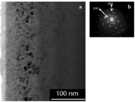
FIG. 3. Bright-field TEM micrographs of YSZ implanted with 300 keV Cs ions at RT for increasing fluences. Diffraction patterns shown in inset were taken on damaged zone. At the same spatial scale, disorder 共fD兲 profiles
measured by RBS/C are given for comparison. At 5⫻1016 cm−2, is also
given the measured Cs distribution measured by RBS.
by the virgin substrate. Initially the damaged zone was cen-tered at a depth d = 64⫾2 nm, close to Rp= 67 nm
calcu-lated from the TRIMcode. As the ion fluence increases, the damaged layer expands toward greater depths, while the sur-face layer is slightly damaged. The depth and width measure-ments of the damaged layer are in good agreement with de-fect profiles obtained from RBS/C. Up to 5⫻1015 cm−2共i.e.,
21 dpa兲, diffraction patterns of the damaged zone 共inset of Fig.3兲 shows a residual crystalline structure and the absence
of extra reflections. No secondary or amorphous phase is evidenced. Diffraction contrasts are not consistent with the presence of dislocation loops. They are rather diffuse dots which do not display a specific Burgers vector. In Xe-implanted samples, we previously observed identical defect clusters in the same dpa range.27Thus, these clusters are not produced by a chemical effect due to Cs. HRTEM observa-tions carried out on the sample implanted with 9 ⫻1014 cm−2Cs ions reveal a mosaic of nanometer-sized
do-mains with a distorted lattice. These distorted areas induce large strain fields, causing spatial variations of the contrast in their vicinity共Fig.4兲. This micrograph also confirms the
ab-sence of any amorphous region, which would present an ape-riodic structure.
At high fluence共5⫻1016 cm−2兲, Cs implantation leads
to the formation of an amorphous layer whereas YSZ did not undergo amorphization under Xe irradiation up to high fluences.11,28The amorphous character is observable on the micrograph共Fig.3兲 via the loss of diffraction contrast in the
central part. This layer共between 20 and 105 nm兲 agrees very well with the RBS/C damage profile and corresponds to fD
⬃1. The amorphous character is also confirmed by the pres-ence of a diffuse ring in the selected area electron diffraction 共SAED兲 pattern. No secondary phase is observed. Comple-mentary in situ experiments共at 70 keV兲 established via the occurrence of a ring on the SAED pattern that amorphization occurs at a fluence threshold of 4⫻1016 cm−2,
correspond-ing to a concentration of about 2.3 at. % at Rp, according to
theTRIMcode.
2. Microstructure after RT implantation and annealing Thermal treatment of implanted bulk samples was per-formed up to 750 ° C in order to follow the thermodynamic evolution of defects and to study the possibility of secondary phase formation. Annealing was carried out in situ on cross-sectional TEM samples. No structural modification was de-tected on samples implanted with 5⫻1015 cm−2. Thus, the defects formed at this implantation fluence are thermally stable up to 750 ° C. Conversely, the amorphous zone ob-served at 5⫻1016 cm−2 undergoes nonepitaxial recrystalli-zation, as shown in Fig. 5. This recrystallization starts at 600 ° C. The micrograph recorded in off-Bragg conditions shows rounded crystallites in the previously amorphized zone. On the SAED pattern, we easily identified the diffrac-tion rings consistent with the 共200兲 and 共220兲 spots. Addi-tional rings were indexed and correspond to the distance dhkl
of the cubic zirconia. The共111兲 and 共311兲 rings are marked 共arrows兲 in Fig.5共b兲. We observed no other phase. Previous experiments29 showed almost total release of implanted Cs above a temperature threshold of 600 ° C. Thus, we conclude that the recrystallization of Cs-rich amorphous YSZ occurs concurrently with the release of Cs atoms. It is worth noting that cavities are formed in the recrystallized area as well as in the surface layer.
3. Microstructure after HT implantation
Cs implantations were also performed at 750 and 900 ° C in bulk samples. To follow the damage buildup at low fluence, TEM experiments were performed in situ during
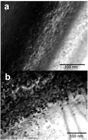
Cs implantation at 70 keV. Figure 6 compares, at RT and
750 ° C, the microstructures of the samples implanted at 3 ⫻1014 cm−2共i.e., 0.9 dpa兲. The structure and size of defects
are obviously affected by the implantation temperature. At RT关Fig.6共a兲兴, small diffuse dots are observed 共with a diam-eter below 7 nm兲. This mottled feature consists of distorted nanodomains as demonstrated previously. At 750 ° C, the im-planted sample is clearly more damaged and point defects have coalesced to form dislocation loops with a size ranging from 10 to 20 nm 关Fig.6共b兲兴. The dislocation loop density
5 nm
FIG. 4. HRTEM micrograph showing the distorted areas in YSZ after Cs implantation at RT with a fluence of 9⫻1014 cm−2.
FIG. 5.共a兲 Bright-field underfocus TEM micrograph of YSZ implanted with 300 keV Cs ions共5⫻1016 cm−2兲 and annealed at 750 °C during 1 h.
Re-crystallization occurs by the formation of rounded nanocrystals. Between crystallites, cavities are visible in this underfocused image. Note that in off-Bragg conditions, the contrasts of distorted domains created in the deeper crystalline damaged zone are not visible here but they are present as these defects are not annealed at this temperature.共b兲 Diffraction pattern corresponding to the TEM image. Non epitaxial recrystallization is associ-ated with the apparition of rings corresponding to the YSZ lattice parameters.
increases with fluence. These observations agree with the
continuous buildup of fD at HT observed by RBS/C. The
nature of these loops is currently under investigation. Pre-liminary results indicate that they are probably perfect interstitial-type dislocation loops.
At higher fluence, the structural evolution was observed by TEM on cross-sectional samples implanted with 300 keV Cs ions. The damage zone undergoes significant broadening with increasing fluence. Above 1016 cm−2 共1.8 at. %兲, the
damaged layer exhibits two different microstructures as a function of depth 共Fig. 7兲. 共1兲 The subsurface 共which
ex-pands up to 60 nm兲 contains bubbles, and 共2兲 the deeper zone 共between 60 and 150 nm兲 shows dislocation loops. When the defects were tilted away from contrast, we observed cracks in the damaged region. These fractures are mostly situated at the end of the bubble zone. The results are similar for both temperatures, the bubble and fracture sizes being larger at 900 ° C. Increasing the fluence up to 5⫻1016 cm−2 induces
bubble growth at the surface and their expansion toward greater depth 共115 nm兲, but does not lead to amorphization
共Fig. 8兲. The SAED pattern shown in the inset of Fig. 8
confirms the absence of amorphization and exhibits satellite spots near some of the main Bragg reflections. These extra spots are related to Moiré fringes sometimes visible on mi-crographs recorded under two-beam conditions. They are presumably due to grain misorientation. The diffraction pat-tern reveals no precipitation of any additional phase.
Assum-ing rotation, the distance between the main spot and the extra one was measured on a series of diffraction patterns and corresponds to a mean angle of 5°. HRTEM observations were carried out to confirm the formation of low-angle grain boundaries. Figure9clearly shows two domains having lat-tice planes misoriented by about 8°. The position of some dislocations is indicated 共arrows兲 on the figure. They are aligned to form a boundary between the two domains. The Fourier transform of this micrograph indicates the presence of two sets of zone axis patterns rotated relative to each other. Therefore, a temperature increase during implantation leads neither to formation of cesium zirconate nor other solid precipitates in the matrix, nor to amorphization, but enhances dislocation mobility, resulting in polygonization.
4. Cs solubility
Depth distributions of implanted Cs atoms were deduced from random RBS spectra and compared at RT and 900 ° C
共Fig. 10兲. Concentrations expected at the maximum of Cs
b
a
b
FIG. 6. Bright-field TEM micrographs of YSZ implanted in situ with 70 keV Cs ions共3⫻1014 cm−2, 0.9 dpa兲 共a兲 at RT and 共b兲 at 750 °C. Images
were recorded in Bragg conditions using g = 111.
(1)
(2)
FIG. 7. Bright-field TEM micrographs of YSZ implanted with 300 keV Cs ions共1⫻1016 cm−2兲 at 900 °C. The general view shows the overall
dam-aged zone with two beam dynamical conditions. In inset is presented, with the same space scale, the subsurface layer recorded with off-Bragg and underfocus image conditions showing the presence of bubbles.
FIG. 8. Under focus TEM micrograph recorded in off-Bragg condition on a cross section of YSZ implanted with 5⫻1016 cm−2Cs ions at 900 ° C.
profile 共Cmax兲, simulated by TRIM, are shown in TableI. At low fluence, the experimental concentrations were in excel-lent agreement with the TRIM values and the profiles were similar at both implantation temperatures. At high fluences, Cs distributions plotted in Fig.10depended strongly on the implantation temperature. At RT, the concentration increased with fluence. At 5⫻1016 cm−2, C
max as measured by RBS
was about 18% below the value expected from TRIM
共9.2 at. %兲. This is likely due to sputtering during
implanta-tion, not accounted for in our TRIM calculations. At 1
⫻1016 cm−2, the measured C
max at HT was slightly lower
than at RT. Moreover, for higher fluences 共3⫻1016 cm−2兲,
the concentration at HT did not increase as expected from TRIM calculations, but saturated at about 1.5 at. %. The Cs distribution at HT also showed Cs diffusion and significant release at the surface. Finally, at 5⫻1016 cm−2 C
max was
about 1.4 at. % when Cs was implanted at HT, whereas 7 at. % of Cs was retained in the matrix at RT.
Previously we pointed out bubble formation in the sub-surface of YSZ共up to 60 nm兲 at 900 °C and at a fluence of 1⫻1016 cm−2. A comparison of Figs. 7 and 10 shows that
those bubbles are not located at the Cs peak maximum, but
are formed between the surface and Cmax. The high bubble
density in the first 20 nm below the surface, where the Cs concentration vanishes, supports the idea that most of the bubbles are in fact voids. Note that they are observable above a fluence of 1⫻1016 cm−2when the Cs concentration
tends to saturate. The formation of large voids is thus likely related to Cs release.
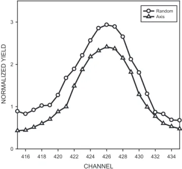
Spectra recorded in the channel range关415–435兴 show a rather large difference depending on whether the analyzing beam is oriented in the random or axial direction, as shown in Fig. 11. In this region of interest, the normalized yield is related to the backscattering on Cs atoms. The peak acquired along the major 具100典 axis exhibits significant lower values than in the random direction. This feature can be explained by assuming that a fraction of Cs atoms is located in substi-tutional lattice sites of the cubic matrix. Accordingly, a solid solution is rather formed instead of cesium zirconate precipi-tates. This observation is in agreement with the absence of incoherent precipitates checked on SAED patterns. In addi-tion, no evidence of coherent precipitates, such as Ashby– Brown contrasts30was found in TEM micrographs, and elec-tron energy loss spectrometry measurements displayed a low and homogeneous repartition of Cs in the TEM cross-sectional sample along the damaged zone. Thus, we conclude that Cs atoms form a solid solution in YSZ at HT with a solubility limit of 1.5 at. %.
IV. DISCUSSION
The results give insight as to the influence of the implan-tation temperature on the structural evolution of cubic zirco-nia and on Cs retention in this material. RBS/C data showed that disorder accumulation is largely dependent on the im-plantation temperature 共Fig.2兲.
For RT implantation, the buildup shows the usual shape of a transitional rise between two plateaus, followed by a FIG. 9. On the right, an HRTEM image showing the polygonization of YSZ
implanted at 900 ° C 共5⫻1016 cm−2兲. Arrows indicate the localization of
some dislocation on the boundary. On the left, the Fourier transform of the micrograph shows two sets of zone axis pattern corresponding to the ob-served two domains rotated relatively to each other.
FIG. 10. Cs profiles obtained by RBS in random direction on YSZ im-planted at RT and 900 ° C with increasing fluences.
CHANNEL 416 418 420 422 424 426 428 430 432 434 NORM A L IZ E D Y IE L D 0 1 2 3 Random Axis
FIG. 11. RBS spectra recorded in random and axial direction in the channel range关415–435兴 corresponding to the Cs signal in YSZ implanted at RT with 1⫻1016 cm−2.
second rapid increase up to amorphization. This latter step only occurs in the case of Cs implantation共not for noble gas atoms兲. This variation of fDmax exhibits a typical multistep
damage accumulation 共MSDA兲 process which may thus be
accounted for with the MSDA model.31Both transitions are related to a collapse of the crystalline structure. The driving force of this transformation is obviously the free energy re-duction of the damaged crystal. The first stage observed at low fluences共below 3 dpa兲 corresponds to the formation of point defects and of tiny distorted nanodomains producing stress fields within the matrix. The stress, inducing a high increase in elastic energy, is likely relaxed by the local for-mation of dislocations. The sharp increase in fDmax共ranging from 3 to 5 dpa兲 is due to the overlapping of these coherent domains共Fig.3兲, which may generate misfit dislocations in
order to decrease the stored elastic energy. The plateau ob-served above 6–7 dpa likely corresponds to a saturation of the number of domains and dislocations, accompanied by a broadening of the damage layer. These first three stages are commonly observed with heavy ion implantation. They are assumed to come from ballistic effects. Up until now, no clear explanation could be proposed for the decrease of fDmax between 1⫻1016and 2⫻1016共cf. Figure2兲. Finally the
sec-ond rise at high fluence is due to a chemical effect induced by the high Cs concentration. The Cs ions can no longer be incorporated in the crystalline structure, and the system mini-mizes its chemical potential by a phase transformation to the amorphous state. Therefore, two successive ballistic and chemical processes are responsible for the damage buildup in cubic zirconia implanted at RT with Cs ions. They are re-spectively defined by the number of dpa and the impurity concentration.
At HT, the monotonous increase of fDmaxversus the
flu-ence can no longer be represented by a MSDA process or by single-step models such as the direct impact and cascade overlap proposed by Gibbons32 or the direct impact/defect stimulated model.33These models show, respectively, expo-nential rise or sigmoidal-shaped dependencies of the disorder versus fluence. The rapid increase of the disorder measured by RBS/C at low fluences 共starting at 1 dpa兲 is due to the early formation of large extended defects. The HT promotes the diffusion and precipitation of point defects to form dis-location loops. The loop density rises with fluence in accor-dance with the linear increase of fDmax. At high fluence, over-lap of the associated stress field of dislocations may be reached. At 5⫻1016 cm−2, the stored energy might be too
high, and mobile dislocations condense to form low-angle grain boundaries and subgrains. This phenomenon does not seem to be transitional in type but rather corresponds to a continuous thermally activated dynamic recovery. The in-crease in fDmaxat the highest fluences is due to the rotation of
subgrains which causes a large direct backscattering of the analyzing beam. Polygonization is a well-known process which allows the system to reduce its elastic energy by rear-rangement and annihilation of dislocations. The thermal con-tribution during implantation allows continuous minimiza-tion of the stored energy in the defective structure, while at RT the damage evolves by discrete structural transformations when the corresponding energetic barrier has been overcome.
It is worth noting that the static recovery after thermal an-nealing of the amorphized layer at RT does not lead to polygonization with low-angle grain boundaries but rather results in a recovered polycrystalline YSZ. The driving force for recrystallization could be the release of Cs atoms above 600 ° C. Further experiments using x-ray diffraction mea-surements are in progress to follow stress evolution as a function of fluence. According to the present results, we be-lieve that at RT stress should increase drastically in the flu-ence range corresponding to the plateaus of damage buildup and the transitional rises should be associated to stress relax-ation due to structural collapse. On the contrary at HT, stress increase as a function of fluence is expected to be monoto-nous.
Whereas cesium zirconate precipitation was predicted to occur at HT,14,21,22 no extra reflections were found in our SAED patterns to confirm the existence of an incoherent phase up to the final fluence of 5⫻1016 cm−2, neither after
post-thermal treatment, nor after HT implantation. Previous
experiments29 showed that thermal postannealing induces
significant Cs release above 600 ° C. The remaining concen-tration falls to 1.5 at. %, i.e., close to the solubility limit estimated by Pouchon et al.14We assume that the recrystal-lization of amorphous Cs-rich YSZ is due to the concentra-tion decrease of Cs atoms. Thermal contribuconcentra-tion during im-plantation also enhances the release at the surface of Cs atoms, associated with the formation of voids. The concen-tration reaches a saturation value of 1.5 at. %. This result again confirms the calculated solubility limit of Pouchon et
al.14 At HT, Cs becomes volatile and acts as a gas in the matrix. However, the observed “bubbles” do not result from gas atom accumulation since they are actually cavities. The nucleation and growth of voids are due to clustering of mo-bile vacancies. However, it is now considered that gas atoms play a significant role in void nucleation, i.e., they are nec-essary to stabilize small vacancy clusters. Our results suggest that Cs atoms are not strongly trapped but are rather ther-mally dissociated from vacancy complexes and can migrate out of the matrix. Void growth likely takes place by vacancy absorption. The complete mechanism is not clearly identi-fied. Further experiments are needed.
As regards the use of YSZ as IMF, the Cs concentration produced in the fuel must be lower than the solubility limit. On the other hand, the formation of voids and grain bound-aries may be deleterious for the mechanical behavior of the matrix. Polygonization may be a general phenomenon at HT due to dislocation mobility. The chemical contribution does not seem to play a significant role in this process. Similar experiments should be performed with Xe ions to verify this point.
V. CONCLUSION
We have studied the temperature dependence of Cs re-tention in YSZ as well as the influence of temperature on the damage created by implantation. Results indicate that no pre-cipitate crystalline phase is formed in YSZ whatever the im-plantation temperature. At RT, Cs concentration exceeds the solubility limit共1.5 at. %兲 and induces amorphization of the
matrix at a threshold of 2.5 at. %. On the contrary, Cs atoms cannot be retained in YSZ at concentration higher than 1.5 at. % above 750 ° C. This temperature is foreseen to be exceeded in reactor operation. Contrary to what was ex-pected from thermodynamical calculations, no precipitation of cesium zirconate is formed during HT implantation and Cs atoms remain in solid solution up to the solubility limit. As the temperature increases, Cs mobility is enhanced and Cs release toward the surface is observed without precipita-tion. The release mechanism is accompanied by void forma-tion.
Damage buildup at RT evolves by discrete structural transformations. Two transitions are observed and are related to the reduction of free energy by collapse of the crystalline defective structure. Two successive mechanisms are involved in this damage evolution. First, a ballistic effect produces strained distorted nanodomains which relax by the formation of dislocations. Second a chemical contribution leads to amorphization. The amorphous layer is recrystallized by thermal annealing. Cs release is likely the necessary condi-tion for this recrystallizacondi-tion. On the contrary, at HT, the disorder increases almost linearly with the ion fluence. Dis-location loops are formed and undergo rearrangement to form grain boundaries at high fluence. This polygonization induces grain rotation. We assume that this process takes place to continuously minimize the stored energy by precipi-tation of point defects in the defective structure, explaining why the buildup is no longer transitional. Heating during implantation allows dynamical recovery starting from the lo-cal rearrangement of dislocations whereas a postimplantation thermal anneal induces nonepitaxial recrystallization by nucleation of YSZ crystallites when Cs is released.
ACKNOWLEDGMENTS
The authors are grateful to the SEMIRAMIS team who made these experiments possible. We acknowledge M. Drouet for complementary high fluence implantations. We are indebted to the LSI in Palaiseau for open access to the microscope, especially to G. Rizza and G. Jaskierowicz. One of the authors would like to thank A. Claverie for helpful discussions on TEM results.
1C. Degueldre, U. Kasermeyer, F. Botta, and G. Ledergerber, Mater. Res.
Soc. Symp. Proc. 412, 15共1996兲.
2C. Degueldre and J. M. Paratte,J. Nucl. Mater.274, 1共1999兲.
3C. Degueldre, J. Alloys Compd. 444–445, 36共2007兲. 4H. Kleykamp,J. Nucl. Mater.275, 1共1999兲.
5V. M. Oversby, C. C. McPheeters, C. Degueldre, and J. M. Paratte, J. Nucl. Mater.245, 17共1997兲.
6G. Ledergerber, C. Degueldre, P. Heimgartner, M. A. Pouchon, and U.
Kasemeyer,Prog. Nucl. Energy38, 301共2001兲.
7W. L. Gong, W. Lutze, and R. C. Ewing,J. Nucl. Mater.277, 239共2000兲. 8B. Savoini, D. Caceres, I. Vergara, R. Gonzalez, and J. E. Munoz
San-tiuste,J. Nucl. Mater.277, 199共2000兲.
9W. J. Weber, R. C. Ewing, C. R. A. Catlow, T. Diaz de la Rubia, L. W.
Hobbs, C. Kinoshita, H. Matzke, A. T. Motta, M. Nastasi, E. K. H. Salje, E. R. Vance, and S. J. Zinkle,J. Mater. Res.13, 1434共1998兲.
10L. Thomé, J. Fradin, J. Jagielski, A. Gentils, S. E. Enescu, and F. Garrido, Eur. Phys. J.: Appl. Phys.24, 37共2003兲.
11K. E. Sickafus, H. Matzke, T. Hartmann, K. Yasuda, J. A. Valdez, P.
Chodak Iii, M. Nastasi, and R. A. Verrall,J. Nucl. Mater.274, 66共1999兲. 12M. Wang, S. X. Wang, and R. C. Ewing, Philos. Mag. Lett. 80, 341
共2000兲.
13M. A. Pouchon, M. Döbeli, and C. Degueldre,Nucl. Instrum. Methods Phys. Res. B148, 783共1999兲.
14M. A. Pouchon, M. Dobeli, C. Degueldre, and M. Burghartz, J. Nucl. Mater.274, 61共1999兲.
15M. A. Pouchon, C. Degueldre, and M. Dobeli, Prog. Nucl. Energy 38, 275
共2001兲.
16C. Degueldre, M. Pouchon, M. Dobeli, K. Sickafus, K. Hojou, G.
Lederg-erber, and S. Abolhassani-Dadras,J. Nucl. Mater.289, 115共2001兲. 17J. Jagielski, L. Thomé, C. Binet, F. Garrido, M. Mozetic, and A. Zalar,
Nucl. Instrum. Methods Phys. Res. B 161–163, 686共2000兲.
18L. Thome, A. Gentils, F. Garrido, and J. Jagielski, Prog. Nucl. Energy 38,
277共2001兲.
19C. Hellwig, M. Streit, P. Blair, T. Tverberg, F. C. Klaassen, R. P. C.
Schram, F. Vettraino, and T. Yamashita,J. Nucl. Mater.352, 291共2006兲. 20M. Streit, W. Wiesenack, T. Tverberg, C. Hellwig, and B. C. Oberlander,
J. Nucl. Mater. 352, 349共2006兲.
21T. M. Chen, S. M. Kauzlarich, and J. D. Corbett, J. Nucl. Mater. 151, 225
共1988兲.
22E. H. P. Cordfunke and R. J. M. Konings, J. Nucl. Mater. 201, 57共1993兲. 23J. F. Ziegler, J. P. Biersack, and U. Littmark, The Stopping and Range of
Ion in Matter共Pergamon, New York, 1985兲.
24N. Chauvin, S. Henry, H. Flocard, F. Fortuna, O. Kaitasov, P. Pariset, S.
Pellegrino, M. O. Ruault, Y. Serruys, and P. Trocellier, Nuclear Instrum. Methods Phys. Res. B 261, 34共2007兲.
25M. O. Ruault, J. Chaumont, and H. Bernas, Nucl. Instrum. Methods Phys.
Res. 209–210, 351共1983兲.
26L. Thomé, A. Gentils, F. Garrido, and J. Jagielski, Mater. Res. Soc. Symp.
Proc. 792, 49–60共2004兲.
27L. Vincent and L. Thomé共unpublished兲.
28I. V. Afanasyev-Charkin and K. E. Sickafus, J. Nucl. Mater.306, 112
共2002兲.
29L. Thomé, A. Gentils, S. E. Enescu, H. Khodja, and T. Thomé, Nucl.
Instrum. Methods Phys. Res. B 249, 326共2006兲.
30M. F. Ashby and L. M. Brown, Philos. Mag. 8, 1649共1963兲. 31J. Jagielski and L. Thomé, Vacuum 81, 1352共2007兲. 32J. F. Gibbons,Proc. IEEE60, 1062共1972兲.
33N. Hecking, K. F. Heidemann, and E. Te Kaat,Nucl. Instrum. Methods Phys. Res. B15, 760共1986兲.