HAL Id: tel-01166045
https://tel.archives-ouvertes.fr/tel-01166045
Submitted on 22 Jun 2015
HAL is a multi-disciplinary open access
archive for the deposit and dissemination of sci-entific research documents, whether they are pub-lished or not. The documents may come from teaching and research institutions in France or abroad, or from public or private research centers.
L’archive ouverte pluridisciplinaire HAL, est destinée au dépôt et à la diffusion de documents scientifiques de niveau recherche, publiés ou non, émanant des établissements d’enseignement et de recherche français ou étrangers, des laboratoires publics ou privés.
Growth from melt by micro-pulling down (µ-PD) and
Czochralski (Cz) techniques and characterization of
LGSO and garnet scintillator crystals
Valerii Kononets
To cite this version:
Valerii Kononets. Growth from melt by micro-pulling down (µ-PD) and Czochralski (Cz) techniques and characterization of LGSO and garnet scintillator crystals. Theoretical and/or physical chemistry. Université Claude Bernard - Lyon I, 2014. English. �NNT : 2014LYO10350�. �tel-01166045�
1
N° d’ordre Année 2014
THESE DE L‘UNIVERSITE DE LYON Délivrée par
L’UNIVERSITE CLAUDE BERNARD LYON 1 ECOLE DOCTORALE
Chimie
DIPLOME DE DOCTORAT (Arrêté du 7 août 2006)
Soutenue publiquement le 15 décembre 2014 par
VALERII KONONETS Titre
Croissance cristalline de cristaux scintillateurs de LGSO et de grenats à partir de l’état liquide par les techniques Czochralski (Cz) et micro-pulling down (μ-PD) et leurs
caractérisations Directeur de thèse : M. Kheirreddine Lebbou Co-directeur de thèse : M. Oleg Sidletskiy JURY
Mme Etiennette Auffray Hillemans Rapporteur
M. Alain Braud Rapporteur
M. Alexander Gektin Examinateur
M. Christophe Dujardin Examinateur
M. Julien Houel Examinateur
M. Kheirreddine Lebbou Directeur de thèse
2
UNIVERSITE CLAUDE BERNARD - LYON 1
Président de l’UniversitéVice-président du Conseil d’Administration
Vice-président du Conseil des Etudes et de la Vie Universitaire Vice-président du Conseil Scientifique
Directeur Général des Services
M. François-Noël GILLY
M. le Professeur Hamda BEN HADID M. le Professeur Philippe LALLE M. le Professeur Germain GILLET
M. Alain HELLEU
COMPOSANTES SANTE
Faculté de Médecine Lyon Est – Claude Bernard
Faculté de Médecine et de Maïeutique Lyon Sud – Charles Mérieux
Faculté d’Odontologie
Institut des Sciences Pharmaceutiques et Biologiques Institut des Sciences et Techniques de la Réadaptation
Département de formation et Centre de Recherche en Biologie Humaine
Directeur : M. le Professeur J. ETIENNE Directeur : Mme la Professeure C. BURILLON Directeur : M. le Professeur D. BOURGEOIS Directeur : Mme la Professeure C. VINCIGUERRA Directeur : M. le Professeur Y. MATILLON Directeur : Mme. la Professeure A-M. SCHOTT
COMPOSANTES ET DEPARTEMENTS DE SCIENCES ET TECHNOLOGIE
Faculté des Sciences et Technologies Département Biologie
Département Chimie Biochimie Département GEP
Département Informatique Département Mathématiques Département Mécanique Département Physique
UFR Sciences et Techniques des Activités Physiques et Sportives Observatoire des Sciences de l’Univers de Lyon
Polytech Lyon
Ecole Supérieure de Chimie Physique Electronique Institut Universitaire de Technologie de Lyon 1 Ecole Supérieure du Professorat et de l’Education Institut de Science Financière et d'Assurances
Directeur : M. F. DE MARCHI
Directeur : M. le Professeur F. FLEURY Directeur : Mme Caroline FELIX Directeur : M. Hassan HAMMOURI
Directeur : M. le Professeur S. AKKOUCHE Directeur : M. le Professeur Georges TOMANOV
Directeur : M. le Professeur H. BEN HADID Directeur : M. Jean-Claude PLENET Directeur : M. Y.VANPOULLE
Directeur : M. B. GUIDERDONI Directeur : M. P. FOURNIER Directeur : M. G. PIGNAULT
Directeur : M. le Professeur C. VITON
Directeur : M. le Professeur A. MOUGNIOTTE Directeur : M. N. LEBOISNE
3
Acknowledgement
In connection with versatility of this work a lot of scientists from different institutions and countries were involved. Originally the work was done in the frame of collaboration between the Institute for Scintillation Material (ISMA) (Ukraine) and Institut Lumière Matière (ILM), UMR5306 CNRS, Universite de Lyon 1, France.
In the first instance I can never thank enough my supervisors. Dr. Kheirreddine Lebbou taught me how to grow crystals by micro-pulling down method which I have never done before. It is an honor for me to be a PhD student of Dr. Oleg Sidletskiy who is a chief of the Single Crystal Growth Technology Department of ISMA. With their help my work was originally destined for success.
Doctor Etiennette Auffray Hillemans (CERN) and Dr Alain Braud from (CIMAP, Caen University) accepted to review this work as referee and members of the jury. I thank them strongly for their time, and their helpful advices and remarks.
I am eager to express my gratitude to members of the jury that accepted to judge this work: Professor Alexander Gektin (ISMA, Kharkov), Professor Christophe Dujardin (ILM, UCB Lyon 1) and Doctor Julien Houel (ILM, UCB Lyon 1)
This work was realized in the frame of joint cotutelle PHD thesis between UCB Lyon 1 and ISMA, Kharkov. I am deeply indebted to the members of ISMA. I would like to thank for helping me scientists from my home institution. V. Bondar, S. Tkachenko, O. Voloshina, D. Kurtsev, P. Arhipov, S. Vasyukov, E. Galenin and I. Gerasymov from ISMA helped me a lot in the understanding of Czochralski growth process. I am thankful to S. Gridin, S. Neicheva, N. Starzhinsky, I. Zenya (ISMA), V. Baumer and K. Belikov (SSI “Institute for Single Crystals” NAS of Ukraine) for characterization of the grown crystals.
In the course of the work a part of microscopy measurements was made in Semiconductor Physics Department and Institute of Applied Research, Vilnius
4
University, Lithuania. Thank so much to D. Dobrovolskas, G. Tamulaitis and A. Vaitkevičius.
I am very grateful to O. Benamara (ILM) and X. Xu (Shanghai Institute of Optics and Fine Mechanics) for their great assistance during my work in France. I thank very much indeed to G. Patton, F. Moretti for help in the fibers characterization in ILM laboratory provided. Special thanks to A. Belsky and C. Dujardin for their professional advises.
Many thanks to W. Su (Jiangsu University, China) and T. Duffar (SIMAP-EPM, France) whom I am obliged for a modeling of the growth process. Their advices and recommendation were very important to take benefit from the simulation and modeling results.
I am deeply indebted to K. Pauwels, M. Lucchini, A. Benaglia and E. Auffray (CERN, PH-CMX, laboratory 27), who also made testing of grown fibers in Fermi National Laboratory, USA.
This work was supported by the Project FP7-INCO-2011-6 (“SUCCESS”), Eiffel grant, and Project No. 28317ZC in the framework of French-Ukrainian Science and Technical Collaboratrion “DNIPRO”. The study at Vilnius University was funded from the European Community’s Social Foundation under Grant Agreementn. VP1-3.1-ŠMM-08-K-01–004/KS-120000-1756. The works provided in CERN were in the frame of Crystal Clear Collaboration. Part of results were obtained in the frame of INFINHI ANR project, we thank ANR for their financial support.
5
Contents
Abstract ... 7
Introduction ... 10
Chapter I: Literature review ... 14
1.1. Choice of the growth method ... 15
1.2. General information about rare-earth silicates ... 21
1.2.1. General information on GSO ... 22
1.2.2. General information about LSO ... 24
1.2.3. Structure of mixed LGSO:Ce crystals ... 26
1.2.4. The improvement of scintillation properties in mixed LGSO:Ce crystals ... 33
1.3. General information on garnets scintillators. LuAG, LuAG:Ce, YAG:Ce and LuAG :Pr crystals ... 38
1.3.1. LuYAG:Ce mixed crystal ... 43
1.3.2. YAGG:Ce mixed crystals ... 46
Chapter II: Growth and characterization methods ... 47
2.1. Raw materials preparation ... 48
2.2. Growth of LGSO crystal by the μ-PD method ... 49
2.3. LGSO:Ce characterization methods ... 52
2.3.1. Determination of crystal structure and composition ... 52
2.3.2. Optical and scintillation measurements ... 53
2.3.3. Microscopy measurements ... 54
2.4. Growth of LuAG, LuAG:Ce, LuAG:Pr, YAG:Ce and LuYAG:Ce by the μ-PD method ... 61
2.5. Garnet crystals characterization methods ... 62
2.5.1. Attenuation length measurements ... 62
2.5.2. Cathodoluminescence ... 64
2.6. YAGG:Ce growth by the Czochralski method ... 64
2.7. YAGG:Ce characterization methods ... 66
Chapter III: Results & Discussion: Growth and characterization of LGSO:Ce fibers ... 68
3.1. LGSO:Ce fiber growth by the micro-PD method ... 69
3.2. Structure and cation distribution coefficients in LGSO:Ce ... 70
3.3. Optical and scintillation properties ... 72
3.4. Confocal and wide-field microscopy measurements ... 75
3.4.1. Selection of samples ... 75
6
3.4.3. Photoexcitation ... 78
Chapter IV: Results & Discussions: Growth and characterization of garnet fibers ... 84
4.1. Numerical study and analysis limits of the micro-pulling down technique for LuAG fiber crystal growth 85 4.2. Growth of undoped LuAG fibers ... 96
4.3. Growth of Ce- and Pr doped LuAG fibers ... 103
4.4. Effect of thermal annealing on LuAG and LuAG:Ce attenuation lengths ... 114
4.5. Growth of YAG:Ce fibers ... 116
4.6. Homogeneity plots ... 119
4.7. Activator distribution in the LuAG:Ce and LuYAG:Ce fibers. ... 123
4.8. Results of LuAG and LuAG:Ce fibers testing for calorimetry applications. ... 124
4.8.1. Construction of the test beam setup ... 124
4.8.2. Cherenkov and scintillating fiber response. ... 126
Chapter V: Results & Discussion: Growth and characterization of Y3Al5-xGaxO12:Ce mixed scintillation crystals. ... 129
5.1. Structure and composition of Y3Al5-xGaxO12:Ce solid solutions ... 130
5.2. Scintillation and luminescence properties ... 135
Conclusion and future works ... 139
7
Abstract
A set of rare earth orthosilicate and garnet scintillators were grown by the micro-pulling down (μ-PD) and Czochralski methods. Ce-doped Lu2xGd2-2xSiO5 (LGSO:Ce) fibers were grown by the micro-pulling down (μ-PD) method for the first time. In order to determine the optimal activator concentration with regard to the best scintillating parameters, cerium concentration in the melt was varied within 0.01-1.5 at.%. A set of results on optical and scintillation characteristics of the grown fibers with the different activator content was determined and discussed. Distribution of Gd3+ and Ce3+ in LGSO:Ce structure was compared to the Czochralski grown crystals. Spatial distribution of cations across LGSO:Ce scintillation shaped crystals grown by the micro-pulling-down method is studied using wide-field microscopy under simultaneous excitation of both cerium-related centers and confocal microscopy under selective excitation of Ce3+ in CeO6 crystallographic sites.
Undoped fibers of Lu3Al5O12 (LuAG) and doped by Ce3+, Pr3+, mixed (Lu,Y)3Al5O12 (LuYAG) and Y3Al5O12 (YAG) both doped by Ce3+ were produced to evaluate a possibility of their potential use in the new dual-calorimeter planned to operate in the upgraded Large Hadron Collider in CERN. The choice of grown crystals was made to detect scintillation (activated materials) and Cherenkov radiation (LuAG). Growth conditions for the improvement of fibers quality were selected basing on measurements of attenuation length of the fibers. The activator segregation coefficient in LuAG:Ce and LuYAG:Ce fibers was evaluated by the cathodoluminescence measurements. The effect of annealing and radiation damage was studied. The good productivity of the grown fibers was verified on the test beam calorimeter.
Structure and scintillation yield of Y3(Al1-xGax)5O12:Ce solid solution crystals are studied. Crystals are grown from melt by the Czochralski method. Distribution of host cations in crystal lattice is determined. The trend of light output at Al/Ga substitution in Y3(Al1-xGax)5O12:Ce is determined. Light output in mixed crystals reaches 130%
8
comparative to Ce-doped yttrium–aluminum garnet. The evolution of luminescence properties at Al/Ga substitution is studied.
Keywords: μ-PD method, high energy physics, oxides, silicates, garnets, scintillation
crystals, fibers, light yield, attenuation length.
Résumé
Des lots de terres rares d’orthosilicates et de grenats scintillateurs ont été cristallisés par les méthodes micro-pulling down (μ-PD) et Czochralski. Pour la première fois des fibres Lu2xGd2-2xSiO5 dopées Ce (LGSO:Ce) (x = 0.5) ont été tirées par la méthode micro-pulling down (μ-PD). Dans le but de déterminer la concentration optimale de l’ion activateur avec les meilleurs paramètres de scintillation, la concentration du cérium dans le liquide a été variée dans l’intervalle 0.01-1.5at%. En fonction de la concentration de l’ion activateur nous avons discuté les caractéristiques optiques et scintillatrices dans les fibres cristallisées. La distribution du Gd3+ et du Ce3+ dans la structure LGSO :Ce a été comparée à celle des cristaux tirés par la méthode Czochralski. La distribution spatiale des cations le long des cristaux LGSO :Ce tirés par la méthode de la micro-pulling down a été étudiée par microscopie à champ proche et microscopie Confocale à travers l’excitation du Ce3+ sur les sites cristallographiques du CeO6. Des fibres de composition Lu3Al5O12 (LuAG) non dopées et dopées Ce3+ et Pr3+, des matrices mixtes (Lu,Y)3Al5O12 (LuYAG) et Y3Al5O12 (YAG) dopés Ce3+ ont été fabriqués pour evaluer les possibilités de développer un calorimètre dual-readout pour fonctionner dans le Grand collisionneur de hadrons du CERN. Les cristaux LuAG ont été choisis dans le but de détecter la scintillation (ion activateur) et les radiations Chernkov. Pour confirmer l’amélioration de la qualité des fibres cristallines à travers les conditions de croissance cristalline, nous avons réalisé des mesures d’atténuation le long des fibres. Le coefficient de ségrégation de l’ion activateur dans le LuAG :Ce et LuYAG:Ce a été évalué par des mesures de cathodoluminescence. L’effet du recuit et la résistance aux radiations ont été étudiés. La bonne reproductivité des fibres a été vérifiée par des tests faisceau en conditions de calorimètre. Nous avons étudié la
9
structure et la scintillations dans les cristaux appartenant à la solution solide Y3(Al 1-xGax)5O12:Ce. Les cristaux ont été tirés à partir de l’état liquide par la méthode Czochralski. La distribution des cations de la matrice a été étudiée. L’effet de la substitution du Al/Ga dans Y3(Al1-xGax)5O12:Ce sur le rendement de scintillation a été déterminé. Le rendement de scintillation a atteint 130% par rapport au grenat aluminium-yttrium dopé Ce. L’évolution des propriétés de luminescence en fonction de la substitution Al/Ga a été étudiée.
Mots clés : méthode μ-PD, Physique des hautes énergie, oxydes, silicates, grenats,
10
Introduction
Single crystal materials are widely used as detectors of ionizing radiations. Scintillation materials emit light when undergo ionizing radiation. Improvement of trustworthy and acquisition speed of medical diagnostics devices, border control and security systems is a driving force of search for new scintillators with improved properties. In the last decades, application of crystalline materials in ionizing radiation detectors has played a crucial role in fundamental research and promoted continuous progress in the detecting technique leading to huge electromagnetic calorimeters such as the CMS-ECAL at LHC [1] or future projects such the PANDA-EMC at FAIR [2]. The high quality of the CMS electromagnetic calorimeter based on PbWO4 (PWO) and its good performance has allowed the discovery of the Higgs boson [3]. New concepts for next generation experiments include combined electromagnetic (EM) and hadron calorimeter based on dual readout by detecting the Cherenkov and scintillation light in different fiber materials [4]. The construction at FAIR, the announcement of the LHC upgrade (HL-LHC) and intensive developments of the ILC Program [5] will require cheap and radiation hard materials, capable for mass production.
For the decades scientists try to improve the scintillation efficiency of materials and to find new practical applications for them. Taking in account the difference in requirements to scintillators for the range of applications, there is no ideal scintillator. High scintillation yield and density, low cost are the basic criteria of material choice for most of applications. Nowadays the design of scanning devices in high energy physics, medicine and introscopy is based on different single crystal materials. Inorganic single crystals are the most appropriate due to the high density and stopping power, and the high light yield. Aluminates and silicates which are studied in this work rank among the most popular compounds used in these applications. For instance, the improvement of energy resolution of hadrons and jets measurements in high energy physics could be achieved in Lu3Al5O12 (LuAG) fibers doped with Ce3+ [4, 6, 7]. Different inorganic scintillators are used in the positron emission tomography (PET) to identify
11
abnormalities in human and animal bodies [8, 9, 10]. High afterglow level in many oxide scintillators interferes their application in ranges where operation speed (computer tomography) or large signal-to-noise ratio (introscopy) are needed [11]. In this connection, Lu2xGd2-2xSiO5:Ce (LGSO:Ce) crystal can be considered as a promising scintillation material [11, 12, 13, 14].
LGSO is the one from the series of new efficient scintillators developed recently on the base of mixed crystals. Among the examples one can note solid solutions of oxide scintillators, such as Lu2xY2-2xSiO5:Ce (LYSO) [15], LuxY1-xAlO3:Ce (LuYAP) [16], LuxGdyY1-x-yAlO3:Tm [17] (LuxGd1-x)3(AlyGa1-y)5O12:Ce (LuGAGG) [18], based on isovalent substitution of host cations. In LYSO:Ce and LGSO:Ce crystals the Lu3+ substitution by Y3+, or Gd3+ improves energy resolution and suppresses afterglow [15, 19]. Light yield in LuYAP at optimal Lu/Y ratio is by twice higher than that in YAP and 4 times higher than that in LuAP [16]. The reported light yield in LuGAGG is more than 40,000 phot/MeV, that is, by several times higher than in its constituents – LuAG or YAG [18]. These examples demonstrate a clear tendency to improvement of scintillation characteristics in (Lu1-xYx)3Al5O12:Ce (LuYAG) and Y3(Al1-xGax)5O12:Ce (YAGG) solid solutions.
Difficulties in crystal growth of some compounds prevent the obtaining good quality boules. Besides the need for efficient scintillators some raw materials for their production are too expensive. Crystal growth methods are also should be verified regarding their economic efficiency. Search for new compounds with the reduced cost is always a “hot” topic. Considering the above factors production of crystals requires the use of different growth methods.
There is an increasing demand for fiber-shaped scintillators used in detectors for high-energy physics and medicine. Micro pulling down (μ-PD) method is well known as a progressive and cheap crystal growth method. This growth approach is widely used for production of different shaped crystals. The inorganic scintillating fibers utilization arises with high detection granularity needs [20]. High stopping power can be obtained only with dense crystals (the density of organic fibers is too small). In addition, the scintillating fibers with the similar shape are convenient for application in medical
12
imaging (positron emission tomography) in a transverse configuration, which requires small pixels combined with depth of interaction as well as good stopping power [21]. This area of interest is a spin-off activity from high-energy detection research. From the beginning of the century a significant progress has been made to control the technology and to improve fiber quality and reproducibility in terms of optical performance.
Future calorimeters require improvement of their performance while operating in intensive conditions. The recent progress in micro-pulling down method allows growing heavy scintillating crystals, like LuAG, directly into fiber geometry of variable lengths and diameters [6, 7]. Exploiting the granularity of the detector is a possible solution which would allow improving the overtaxing and tracking capabilities as well as the description of the shower development. Because of the flexibility of this geometry, combined with the high density and good radiation hardness of the material, such a technology represents a powerful potential for the development of future calorimeters [4, 22, 23].
μ-PD method also attracts interest from the scientific point of view. Besides possibility to grow long and thin fibers it is a fast way to make a single crystal of enough size for examination of new compounds. It is a practicing method to obtain different shaped materials as well. On the other hand it differs a lot from the growing of bulk crystals. Therefore, it is reasonable to compare the outcome of different methods. Nevertheless, the growth of crystals which can be shaped specially for the application with minimal subsequent treatment is one more additional advantage of μ-PD. In this work the feasibility to grow shaped fibers for the use in high energy physics application is demonstrated.
LGSO:Ce shaped crystals represent the example of complications which may arise during the micro-PD growth, in particular, in uniform distribution of the components across the crystal and cracking . These crystals were grown with the main purpose to find out the maximally beneficial activator concentration. In the case of garnet fibers growth the main target was to produce single crystal fibers with the required length for the new dual-readout calorimeter. Aluminates with the garnet structure – undoped LuAG and doped by Ce3+, Pr3+, Y3Al5O12:Ce (YAG:Ce) Ce3+ are
13
relatively easy-to-grow crystals compared to silicates. However, to achieve the required fiber shape and properties the growth technology has to be modified. Drawbacks of the μ-PD grown garnets include inuniformity of activator concentration both in axial and radial directions. This can be overcome by the transfer to mixed Lu3-xYxAl5O12:Ce (LuYAG) crystals with higher segregation coefficient of Ce3+. Besides this, the moderate light yield and density of garnets can be significantly improved by the Al3+/Ga3+ substitution in the host. Both these approaches are successfully implemented in the present work. Also, this work represents a status of the optical quality on recently obtained LuAG fibers and the test beam results obtained with a sampling calorimeter module constructed from 64 LuAG fibers embedded into a brass absorber.
The manuscript thesis is presented as the follows:
Chapter I introduces a literature review and monography about scintillator oxides crystal growth technology and the problem encountered during the growth process. The content also present a large information about GSO, LGSO, YAG, LuAG and rare earth activator dopants such Ce3+ and Pr3+.
Chapter II is focused on the experimental part related to the growth and the characterization of the pulled crystals.
Chapter III presents the results part related to the growth and the characterization of LGSO:Ce fibers.
Chapter IV presents the results part related to the growth and the characterization of Ce-doped garnet fibers.
Chapter V describes the results on bulk Y3Al5-xGaxO12:Ce mixed scintillation crystals as the promising garnet material with the improved light yield and increased density.
The last part summarizes the main conclusions and the outlook for the future research work.
14
15
At present the crystal growers widely produce about two dozen types of inorganic crystalline scintillators. Many other inorganic compounds are considered as good scintillation candidates for scintillation application. In this chapter, we present an overview on silicate (GSO, LGSO) and garnet (YAG, LuAG) scintillating crystals. We have also discussed the achievements in growth of fiber-shaped crystals by micro-pulling down (μ-PD) method.
1.1. Choice of the growth method
The most commonly used single crystal production approach is growth from the melt. Nowadays, depending on the crystal mechanical properties and sizes of the crystals, different methods of growth from the melt are used. In general, growth methods can be divided into two groups. The first group belongs to the growth without a crucible owing to the ability of the melt react with the crucible material, or higher melting temperature of the raw material compared to the crucible melting point. These methods are represented by the Verneuil method [24], Skull method [25], and the Floating Zone method [26].
Crucible-free methods of growing single crystals are used for the industrial production of the crystals. For example, sapphire is grown by the Verneuil method for the jeweler industry and the growth of pure silicon for the electronics by the Floating Zone with high-frequency heating. In most cases, these methods are used for the rapid preparation of crystalline samples or seeds. The main disadvantages of the these methods are the limit of the grown crystal, as well as the relatively high stress in the crystals, resulting from the growth process, and often lead to the destruction of the crystal.
Another group of methods correspond to the growth of crystals from crucible filled with the melt. The most popular growth methods from the melt are Czochralski [27], Kyropoulos [28], Bridgeman [29 - 31] and the variety of the floating zone methods [32]. These methods are commonly used for experimental and industrial growth of large bulk crystals. The comparative features of these methods are discussed in [32 - 39].
16
Since LGSO and LuAG were reported as congruent melting materials (solid and liquid have the same composition), it is reasonable to grow them from the melt using Czochralski (Cz) method [40, 41]. LGSO:Ce crystals were grown in all the Lu/Gd substitution range (Figure I.1).
Figure I.1. As-grown LuxGd1−xSiO5:Ce crystals with x = 0.2 (left), x = 0.6 (middle), and x = 0.75 (right) [43].
17
The example of LuYAG crystals grown by the Czochralski method was presented in [42] (Figure I.2).
Need for developing of the technology for large-size crystal production and material losses at cutting of crystals into piece makes Czochralski method relatively more expensive. Crystal growth by the μ-PD method posess a feasibility to obtain single crystals fibers, rods, plates directly after the growth process. Capability of the fast growth and the crystalyzation of 100 % of melt is additional advantage of the μ-PD method [44]. The samples can also be directly produced in a shape suitable for
18
construction of detectors consisting of arrays of different crystals providing high detection granularity [45]. Fibers grown by μ-PD can be used in the development of a new generation of detectors for high-energy physics based on single-crystal fiber design [46].
There is a fertile history of the shaped crystal growth illustrated by numerous publications related to the different applications of plastic/organic scintillators. However, the low effective Z of the atomic components restricts their sensitivity to ionizing radiations. Due to the recent development of the micro pulling down method, fibers based on inorganic crystalline scintillator can be grown with statically improving quality. Relatively novel micro-pulling-down crystal growth method (μ-PD) is well recommended and promissing in production of crystal materials [47, 48]. The μ-PD growth method [49] substantially differs from the Cz method.The molten zone is situated at the bottom of the crucible on its capillary die surface. During the growth, melt flows down through capillary and there is no diffusion of impurities from crystallization interface back to the crucible basic, in contrast Czochralski growth procedure. Therefore, Dopants and, impurities are concnetrated in the molten zone. They are pushed by melt flow to the periphery of the meniscus and, then, are captured by the growing crystal. As the result, the distribution of the components along the fiber remains almost constant. Meanwhile, a substantial gradient of the Ce concentration might appear in the radial direction and have a negative impact on the fiber scintillation characteristics.
Previously fiber-shaped materials with garnet structure were grown by the μ-PD [50, 51] method. The next step at the growth of garnets is enhancement of their growth procedure to minimize the distribution of activator across the fiber. In particular, the production of LuAG:Ce and LYSO:Ce, which are bright scintillators and possess high radiation hardness, and short radiation length, imposes additional complications due to their high melting point and the large difference in geometrical dimensions of the host and activator ions. For both materials, which are considered for a new generation of sampling calorimeters with dual read-out for hadron detection or pure electromagnetic calorimetry and additional applicability in PET-tomography, significant progress has
19
been achieved [6, 7, 52]. The improvement of growth conditions of LuAG and LuAG:Ce fibers was reported in [7]. Such important parameters like wetting of the melt (Figure I.3 a, I.3b), diameter control (Figure I.3c, I.3d) and pulling rate influence were discussed.
Figure I.3. Undoped LuAG (b) grown with conical crucible (a) and LuAG:Ce fibers (d) obtained with crucible with modified cappillary die (c) [7].
In contrast to the Cz grown crystals, there is a radial gradient in activator concentration in fibers grown by μ-PD grown method (Figure I.4) [7]
20
Figure I.4. Transversal cut view of the 0.12 at.% LuAG:Ce fibers excited under X-rays (a) and electrons (b), presenting a distribution of Ce activator to the periphery of the fiber samples [7].
In comparison to fabrication of the pixelated detectors by cutting bulk crystals, micro-pulling down [53] is an efficient method for production of long single crystal fibers of variable cross-section. This method enables reaching the growth rate up to 5 mm/min, which is beyond the limits of the majority of other melt crystal growth methods [54]. The μ-PD method has already been successfully applied for growing complex high-melting-point oxide scintillators: Lu2xY2-2xSiO5:Ce (LYSO:Ce) [52] rare earth garnets [6, 7], Bi4Ge3O12 [55], complex borates [56], etc. Moreover, the μ-PD growth process for mixed crystals is complicated, because the different ionic radii of both the activator Ce3+ and one of the host cations (Gd3+ or Y3+) are significantly larger than that of the Lu3+ host cation [57]. This discrepancy results in cracking of bulk LGSO:Ce crystals. Therefore, the axial and radial distributions of Ce3+ and Gd3+ in the LGSO:Ce fibers were in the focus of the present study.
21
1.2. General information about rare-earth silicates
Oxyorthosilicate phase exists in the system RE2O3-SiO2 (RE – rare-earth element). The oxyorthosilicate inorganic scintillating crystals comprise lutetium oxyorthosilicate (LSO) [58, 59], gadolinium oxyorthosilicate (GSO) [60], yttrium oxyorthosilicate (YSO) [61, 62], which correspond to the RE2SiO5 composition. With the increase of SiO2 percentage the structure changes to the oxyapatite with a general formulae RE9.33Si6O26 [63], pyrosilicates or diorthosilicates with the RE2Si2O7 formula [64, 65]. It is shown for the LSO case in Figure. I.5, that oxyorthosilicate phase exists in the composition range between the lines marked by the arrows 1, 2, 3. With a substitution of one RE1 by another RE2, it is possible to grow mixed crystals.
Figure I.5. Lu2O3 – SiO2 phase diagram [73].
Such examples are represented by lutetium-yttrium oxyorthosilicate Lu2xY 2-2xSiO5 (LYSO) [66, 67], gadolinium-yttrium oxyorthosilicate Gd2xY-2xSiO5 (GYSO) [68, 69], and, finally, lutetium-gadolinium oxyorthosilicate Lu2xGd2-2xSiO5 (LGSO) [70,
22
71]. As a consequence, the nomenclature of crystals became wider [72, 73]. From the variety of scintillating crystals we choose the LGSO:Ce compound for the fiber technology development.
Since LGSO is the mixture of GSO and LSO components, in the following subsections, the properties of these components are reviewed.
1.2.1. General information on GSO
The Gd2SiO5 (GSO) was discovered in 1983 [60]. Ce-doped GSO (GSO:Ce) properties exceed BGO single crystals by light yield and 5 times lower decay time. However, GSO:Ce light yield is by 3 times lower compared to LSO:Ce or YSO:Ce. Nevertheless it is applied in the high energy physics, and nuclear physics. GSO:Ce demonstrate good radiation hardness [74] and has relatively lower production cost due to cheaper raw material components and lower melting temperature. However, the monoclinic P21/c structure of GSO:Ce light yield is insufficient for use in modern PET scanners, and large GSO crystals are difficult to produce because of easy cleavage [75].
The typical excitation and emission spectra of GSO:Ce are shown in Figure. I.6. The maximum wavelength of the scintillator emission spectrum is at 430 nm. The excitation spectrum for the emission at 430 nm has the three peaks at 250 nm, 284 nm, and 340 nm. The excitation peaks at 340, 284, and 250 nm are attributed to the direct excitation of the 4f–5d transitions of Ce3+. The emission spectrum is assigned to 5d-4f transitions of Ce3+.
The another advantage of GSO:Ce crystals is the low afterglow level. On the Figure I.7 one may compare the Ce-doped GSO, LSO, and Gd2Si2O7 (GPS) afterglow curves. Afterglow level for GSO:Ce is by several times lower comparing to LSO:Ce and GPS:Ce (Figure I.7). Phenomenon of afterglow in orthosilicates is usually attributed to the presence of deep oxygen vacancies on non-silicon bound oxygen atoms [77].
23
Figure I.6. Excitation and emission spectra of GSO:Ce crystal at the room temperature [76].
24
1.2.2. General information about LSO
Since 1990s, Lu2SiO5:Ce (LSO:Ce) is produced as one of the best scintillation detector material for PET [79, 80]. LSO with the monoclinic C2/c crystal structure, as a dense, bright and fast scintillation crystals doped by Ce was extensively studied during the recent two decades. The main disadvantage of this chemically stable and non-hygroscopic material is the high afterglow level, which limits the application range of LSO:Ce. In addition, this material melts at 2150°C which is so high for the crucible container such as Iridium material. The LSO scintillation parameters can be optimized by the proper choice of activator content and host composition. The first way is comprised by the codoping with the divalent cations [81], for example, Ca2+. With Ca2+ codoping the higher light yield, lower afterglow, and faster scintillation decay in LSO:Ce crystals were achieved. Meanwhile, the Ca2+ co-doping brings some instability to the crystal growth process [82].
Another way is to modify the properties of LSO:Ce with the incorporation of another host cation. Following this possibility the new Lu2xGd2-2xSiO5:Ce (LGSO:Ce) [11-14] and Lu2xY2-2xSiO5:Ce (LYSO:Ce) [15] mixed crystals were introduced.
The positions of the peaks on LSO:Ce excitation and emission spectra are similar to LYSO:Ce crystals (Figure I.8). The emission maximum at UV-excitation is peaked at 402 nm, and 5 peaks corresponding to the 4f-5d transition in Ce3+ (only 3 peaks are shown in Figure I.8 in the selected wavelength range) with the main peak at 358 nm are observed on excitation spectrum.
25
Figure I.8. Optical properties are shown as a function of wavelength. The excitation and emission spectra correspond to the left vertical scale, and the transmittance spectra correspond to the right one [15].
LSO:Ce in contrast to GSO:Ce has the high light yield around 25000-30000 phot/MeV [83, 84]. The highest light yield is observed with the 0.25 at. % activator content (Figure I.9) [15].
26
Figure I.9. The light output is shown as a function of the cerium concentration in LSO [15].
1.2.3. Structure of mixed LGSO:Ce crystals
The main idea of LGSO:Ce synthesis is a combination of superior properties of GSO:Ce with low afterglow and LSO:Ce with high light yield. Accounting for the lower cost of Gd2O3 in comparison with Lu2O3 and lowering of crystallization temperature with Gd addition into the host, these crystals are good candidates for substitution of LSO/LYSO in PET or CT [85, 86, 87]. Since the first patent concerning LGSO:Ce growth is dated by 1993 [88] this material has been grown by different groups. According to the phase diagrams on the Figure I.5 and the Figure I.10, the oxyorthosilicate phase is formed at the 1:1 ratio in the RE2O3 – SiO2 system. The moderate atomic radii values difference makes it possible to substitute Lu by Gd. As Lu and Gd cations sizes differ, a lot of efforts were done for the investigation of this compound.
27
Figure I.10. Phase diagram for Gd2O3 – SiO2 system [89]
The Gd ionic radius is 0,94 Å and the Lu one is 0,86 Å [68, 90]. This calls the lattice structure switch from the P21/c space group of GSO to the C2/c space group of LSO with the increase of Lu content [43, 91]. The lattice P21/c symmetry occurs until the x = 0.1 in Lu2xGd2-2xSiO5:Ce, and the C2/c symmetry forms starting from x = 0.2. For the growth of crystals with the GSO-type lattice the [010] oriented seeds were used, and the [210] seeds are used for the LSO-type lattice. In the x range from 0.1 to 0.2 the structure type of growing crystal depends on the seed orientation (Figure I.11). The crystals with such ‘intermediate’ compositions often contain cracks and inclusions. Note that LSO structure retains at up to 90% substitution of Lu by Gd.
The change of the space group of symmetry has the impact on the unit cell volume (Figure I.12). In the GSO structure with the addition of up to 20% of Lu the decrease of unit cell volume is observed. The same is observed at 0.2<x< 1 where the unit cell volume decreases down to the parameters of LSO C2/c-type unit cell [91]. The jump of the unit cell volume at x=0.2 is called by the different quantity of atoms in the GSO [88] and LSO [92] elementary cells.
28
Figure I.11. Polymorphism in LGSO crystals [91].
29
In spite of the difference in the ionic radii of the substituted host components, their overall content in crystal is about the same as in melt (Figure I.13). The unit cell with the space group C2/c contains 64 ions. It contains eight lutetium polyhedra LuO7 and eight lutetium polyhedra LuO6. The energy of the substitution of Lu in LuO7 for Ce3+ is equal to +6.90 eV, and the energy of the substitution Ce3+ Lu in LuO6 is +7.25 eV [91]. In both cases, the substitution energy is positive because of the larger ionic radius of Ce3+ (1.01 Å). The different displacements of oxygen ions after the substitutions by Ce3+ in the LuO7 and LuO6 coordination polyhedra are responsible for different rate of Ce3+ incorporation into these sites. The number of Ce3+ ions replacing Lu ions in the different sites affects the light yield, the position of the luminescence maximum, and the scintillation decay time. The same relates to the distribution of Lu3+ and Gd3+ in the six- (LnO6) and sevenfold (LnO7) sites. It is illustrated by Figure I.14.
Figure I.13. Lutetium concentration in the crystal as a function of the melt composition.
30
Figure I.14. Concentration of Lu3+ in crystals with the different space symmetries vs. Lu content in melt. Data on Lu3+ distribution between polyhedra are obtained by X-ray analysis. These results are in good agreement with the values for common Lu content in these crystals determined by the ICP-AES method.
The LGSO phase diagram was studied in [93]. It shows (Figure I.15) the melting temperature for LGSO compositions in the whole range of Lu/Gd substitution. The steep melting temperature fall with the Gd addition is observed within the Gd content 0-84 at. %. This diagram helped to choose the optimal compositions at the fiber growth by micro-pulling down method in this work regarding the scintillation parameters and melting temperature.
31
Figure I.15. Schematic phase diagram for Gd2SiO5- Lu2SiO5 solid-solutions [93].
The LGSO x-ray diffraction patterns difference for the LGSO with the 15% and 17% content of Lu [93] confirms the structure transition between the C2/c and P21/c structures around 16 at.% of Lu (Figure I.16).
32
Figure I.16. X-ray diffraction patterns of the (LuxGd1-xSm0.005)2SiO5 solid solution crystals with x = 0.15 and 0.17 in the melt [93].
33
1.2.4. The improvement of scintillation properties in mixed LGSO:Ce crystals
Three approaches were used to improve the light yield in LGSO-based crystals. The two of them are identical with the case of LSO - the optimization of Ce concentration, which generally should not exceed 0.5 at % [94], and codoping with the divalent ions [95]. In mixed crystal, such as LGSO, we also may optimize the host composition by isovalent substitution of the host cations [19, 96].
The entire range of LGSO mixed crystals with different relation of lanthanides in the host was investigated first in 1997 [90]. No relationship between scintillation characteristics and crystal structure type was observed. The best scintillation characteristics were found in the C2/c structure range. Meanwhile, it was shown that basic scintillation parameters of LGSO:Ce are not deteriorated with the substitution of up to 80 % of Lu3+ in the host [19]. Substitution of Gd3+ and Lu3+ host cations in LGSO, as well as in LYSO:Ce crystals improves energy resolution and suppresses afterglow [19]. The substitution of cations in LGSO:Ce leads to the improvement of scintillation properties. Mixed crystals LGSO:Ce demonstrate the light yield of up to 29000 phot/MeV (33700 Photons/MeV with Ca2+ codoping) and the 6,7 % (662 KeV, 137Cs) energy resolution [43]. The scintillation decay time decreases down to 30 ns. With the increase of Gd concentration in crystals the afterglow level decreases by 1-3 orders of magnitude in comparison to LSO:Ce [43]. The Ce segregation coefficient reaches 0.8 certifying nearly homogeneous chemical composition and a good uniformity of scintillation parameters across the crystal.
Ce concentration in LGSO also affects both the luminescence peak position, and scintillation parameters. It was shown that with the increase of the Ce content in the LGSO (60 % Lu) the luminescence peak shifts towards longer wavelengths and the intensity of luminescence in the 450–500 nm range rises (Figure I.17) [19]. It is caused by a redistribution of Ce into the LuO6 coordination polyhedra. The noticed [97] increase of long-wavelength luminescence intensity in LGSO was accompanied by the improvement of light yield and other scintillation parameters. On the contrary, the light
34
output decrease, increase in the slow decay component contribution, and worsening of the energy resolution was observed in [19] as CeO6 luminescence rises [19].
Figure I.17. Red shift of Ce3+ emission on X-ray luminescence spectra for Lu1.2Gd0.8SiO5:Ce crystals illustrates the rise of impact from CeO6 centers as common Ce3+ concentration increases [19].
X-ray luminescence spectra in dependence on Lu/Gd ratio in the host demonstrate broadening of Ce3+ luminescence band toward longer wavelengths as Gd concentration increases (Figure .I.18). The difference spectra on the inset clearly demonstrate that this effect is called by the rise of 450–500 nm luminescence contribution linked to Ce in
six-35
fold polyhedra. The cerium concentration in all the samples is kept in the range 0.2–0.6 at.% [19].
Figure I.18. X-ray luminescence spectra for all solid-solution range of Lu/Gd substitution and their difference spectra on the inset [19].
36
Figure I.19. Light yield (a), energy resolution (b) at 662 KeV, and afterglow (c) after 5 ms in LGSO:Ce crystals with the C2/c structure vs. Lu concentration in host. The asterisk in the middle section corresponds to the best value of LSO:Ce energy resolution found in the literature. [43]
37
The maximal light yield was observed at around 60 % of Lu concentration in the crystals and at the same time comprised 130% of the LSO:Ce yield (Figures I.19, I.20) [43]. In the case of codoping by Ca2+ the highest light yield was 33700 phot/MeV in crystals with 83% Lu. However, Ca2+ does not influence the energy resolution (8.1% at 662 KeV) and afterglow (0.46% after 5 ms) [43]. As the influence of Ca2+ incorporation was not verified for the compositions with the same Ce content, there is a room for further improvement of scintillation parameters in LGSO:Ce crystals. Comparative parameters of LGSO:Ce and its constituents are presented in the Table 1.
Figure I.20. Pulse height spectra of some LGSO:Ce and LGSO:Ce,Ca crystals in comparison with BGO and LSO:Ce [43].
38
Table 1.Scintillation parameters of GSO:Ce, LSO:Ce, and LGSO:Ce [43, 96]
Crystal GSO:Ce LSO:Ce LGSO:Ce
γ – radiation 137Cs, 662 KeV Light yield, Phot/MeV 8000 25000-30000 up to 29000 Energy resolution, % 9-11 7.3-9.7 6.9-7.3
Decay time, ns 56, slow 40 31
Afterglow level, after 3 ms, % 0.02 5 0.02-0.1
1.3. General information on garnets scintillators. LuAG, LuAG:Ce, YAG:Ce and LuAG :Pr crystals
The A3B5O12 compounds (where A are rare-earth elements and B are Al3+, Cr3+, Fe3+, Ga3+, In3+, Sc3+) complement the diversity of oxide crystals. The most popular scintillation materials in this category are Lu3Al5O12 (LuAG) and lighter Y3Al5O12 (YAG) cubic garnets with the first references since 1928 [98, 99]. The isostructural LuAG- and YAG-based crystals are used for laser and scintillator applications and has a large knowledge base associated with their growth conditions, crystal structure characterization, optical and scintillation properties. Cubic LuAG and other rare earth aluminum garnets were shown to crystallize with the space group symmetry Ia3d. The phase diagram of mixing the Lu2O3 and Al2O3 is shown in Figure I.21 [100]. YAG crystals are formed from Y2O3 and Al2O3 oxides and their phase diagram is also well known (Figure I.22) [101]. The garnet phase is the most stable phase in these binary systems. It can be easily obtained as a single phase via solid-state reaction. Its cubic eight-coordination is favorable for obtaining of transparent ceramics [102].
39
Figure I.21. Phase diagram of the Lu2O3-Al2O3 system. [100]
40
Over the past decade, Ce3+-doped rare earth aluminate crystals, such as Lu3Al5O12:Ce [103, 104, 105], attracted much interest in radiation detection. Ce-doped LuAG and YAG crystals are highly demanded scintillators due to their high hardness, good mechanical and chemical stability, high light yield, variable density from 6.7 g cm -3 in lutetium garnet down to 4.56 cm-3 in yttrium garnet, and relatively short decay time of 60 ns and 90 ns, respectively [103-106].
The luminescence band corresponding to 5d1–4f radiative transitions in Ce3+ garnets is peaked at 500-550 nm, which is in a good match with Si photodiodes spectral sensitivity [107]. The luminescence decay time in the case of Pr-doping is reduced by twice [106], but the luminescence band is located in the deep UV band.
LuAG and LuAG:Ce crystals were previously grown by the different methods, and their properties were presented in connection with the different applications [108, 109, 110]. Y3Al5O12:Ce crystals were thoroughly studied side by side to lutetium garnets [111, 112, 113]. Ce-doped YAG scintillator possesses moderate density (4.55 g/cm3) and light yield (16,000 phot/MeV) [114].
A detailed study of the LuAG and LuAG:Ce fibers growth process was made with a purpose of further usage in high energy physics. The special attention was paid to the improvement of propagation of the scintillating signal along the fibers [7]. The criterion to characterize the transparency of fibers was their attenuation length, that is, the distance where the emission signal weakens by e times [104]. Following the Figure I.23, the authors noticed [7] that with the increase of distance between the falling beam place and the photodetector on the end of the fiber the self-absorption in crystal and reflection losses reduced the propagation of the signal. As the issue, the intensity of luminescence decreased and the emission bands shifted to the longer wavelengths.
With optimization of growth conditions the investigated crystals had shown the promising results on optical attenuation of scintillation light within the fibers (Figure I.24).
41
Figure I.23. Comparison of the normalized emission spectra for 1, 5, 15 and 20 cm distance between the falling beam and the end of the fiber [7].
Figure I.24. Attenuation curves for plastic fiber and Ce (<1 at.%)-doped LuAG fibers as a function of pulling rate [7].
The LuAG:Pr crystals possess a good scintillation properties with the light yield of 17000 phot/MeV, and the 20 ns decay time [106].
42
The antisite defects (Y or Lu ions substituting Al at the octahedral site) are the basic type of intrinsic defects in aluminum garnets [115]. Similarity of thermoluminescence glow curves in the case of Ce-doped and Pr-doped LuAG host, Figure I.25, supports their relation to shallow electron traps, which give rise to thermoluminescence glow peaks within 120–200 K [116]. Both the Ce3+ and Pr3+ ions play the role of recombination centers, which was proved by the characteristic TSL emission spectra (inset of Figure I.25), while TSL glow curves are determined by the similar electron traps in both systems. Light yield of Czochralski-grown Pr-doped LuAG approaches 200% of BGO at the optimized Pr concentration of about 0.2–0.3 mol% [117]. Pr-doped aluminum garnets scintillation characteristics are closely similar for both the μ-PD and Cz methods. Therefore, LuAG:Pr is a very promising fast and efficient scintillator.
Figure I.25. Thermoluminescence glow curves of Pr- and Ce-doped LuAG single crystal after X-ray irradiation at 10 K. In the inset, the TSL spectra taken within 120– 160 K are displayed featuring characteristic Pr3+ and Ce3+ emission, respectively [117].
43
1.3.1. LuYAG:Ce mixed crystal
There is few information on the Lu3(Al1-xGax)5O12:Ce properties in the literature. It is known that undoped bulk crystals were grown by Czochralski method, and their structure was determined and discussed versus LuAG and YAG crystals [92]. The LuYAG:Ce density varies within 4.5 – 6.7 g/cm3 depending on Lu/Y ratio. Variation of the lattice parameters of LuYAG solid solution as a function of x was presented (Figure I.26). The decrease of effective segregation coefficient was observed with increasing of Lu content in the crystals (Figure I.27). The solidification temperature of LuYAG crystals changed almost linearly from 1930°C (YAG) to 2010°C (LuAG) in the solid solution range.
Figure I.26. Lattice parameter of (LuxY1-x)3Al5O12 solid solution. The open circles are those with calibrated compositions based on the Vegard’s law, and the crosses are those without corrections [92].
44
Figure I.27. Effective segregation coefficients keff for Y atoms of (LuxY1-x)3Al5O12 crystals, with a dashed curve fitted by a quadric function passing through the point keff
= 1 at YAG composition for viewing convenience [92].
Mixed Ce3+- or Pr3+-doped LuxY1-xAG (x=0.9-1) crystals show the light yield and energy resolution similar to those in doped LuAG, but the contribution of the slow components into scintillation yield was reduced [118] .
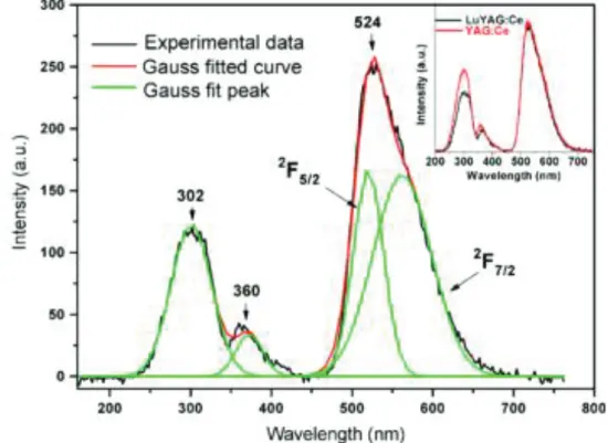
In [107] it was shown that two bands (339 nm and 454 nm) on the LuYAG absorption spectra corresponding to 4f-5d transitions are blue-shifted (Figure I.28) relatively to the annealing atmosphere. The emission band appears at 524 nm at the 468 nm excitation. On the X-ray excited fluorescence spectra the peaks related both to host (302 and 360 nm) and Ce3+ emission at 524 nm were observed (Figure I.29). Authors noticed that Lu ions incorporation into YAG can reduce the population of antisite defects.
45
Figure I.28. Absorption spectra of the LuYAG:Ce crystals [107].
Figure I.29. X-ray excited fluorescence spectra of the as-grown LuYAG:Ce crystal. The figure on the inset is the comparison of X-ray excited fluorescence spectra of the
46
Basically, the reported light yield in LuAG:Pr does not exceed 17000 phot/MeV [106]. However, surprisingly high light yield of 33000 phot/MeV for LuYAG doped with Pr3+ was reported recently [119]. Taking into account the energy resolution of 4.4% (at 662 keV) [119], and the density of 6.2 g/cm3, LuYAG:Pr is a good example of improvement of scintillation parameters in mixed crystals.
1.3.2. YAGG:Ce mixed crystals
Growth of mixed crystals is justified also from the economical point. Substitution of Lu3+ by Y3+ or Gd3+ lowers the production cost due to decrease of raw material cost and decreases the crystallization temperature. Consequently, YAG:Ce or mixed crystals are good alternatives to LuAG and LuAGG-based scintillators.
Y3(Al1-xGax)5O12:Ce (YAGG:Ce) scintillator was studied in the present work. Some structure and luminescence properties of YAGG based materials were reported previously in [120]. Solid solution crystals with garnet structure became popular hosts for laser and optical applications, see for example [121]. However, their application as scintillation host was limited due to low-to-moderate light yield and low density and effective atomic number compared to perovskite- or orthosilicate-based scintillators. For example, Ce-doped YAG scintillator possesses moderate density (4.55 g/cm3) and light yield (16,000 phot/MeV) [114]. Full substitution of Al3+ with Ga3+ leads to the increase the scintillator density up to 5.80 g/cm3 [122]. It was reported [120] that light output efficiency decreases at Al/Ga substitution, however recent results on Lu3(Al 1-xGax)5O12:Ce LuAGG [18] pushed us to more detailed study of yttrium mixed garnets.
Summary
In this chapter, we review the development of inorganic scintillating oxides crystals and the growth technology to get scintillating crystals with the improved performance. Single crystals such Ce doped GSO, LGSO, LSO, LuAG and YAG remain a strategic materials for scintillation and detection applications. The scintillation performances are strongly connected to the crystal composition and the growth technology.
47
48
In this chapter the various experimental methods to grow fiber-shapes and bulk single crystals, and the methods of their optical and scintillation parameters determination are reported in this section.
2.1. Raw materials preparation
At growth of LGSO:Ce fibers the initial growth runs by μ-PD method were accomplished using the broken crystal chunks of LGSO:Ce with x= 0.2 and 0.5 and 0.01 at.% Ce grown by the Czochralski method. At the next research stage, powders of Lu2O3, Gd2O3, CeO2, and SiO2 with purity not worse than 99.99% mixed at stoichiometric ratios were utilized as raw materials for the rest of fibers. SiO2 powder was preliminary calcined at 300 ºC to remove moisture. The synthesis of undoped LGSO by solid state reaction was carried out according to the following chemical reaction:
xLu2O3 + (1-x)Gd2O3 + SiO2 → Lu2xGd2-2xSiO5. (2.1)
As CeO2 is added to the melt, the reaction transforms to:
xLu2O3 + (1-x-y)Gd2O3 + yCe2O3 + SiO2 → Lu2xGd2-2x-2yCe2ySiO5 (2.2)
The Ce+3 activator concentration in the raw material was in the range 0.01 - 1.5 at.%.After the mixing, the second annealing was accomplished at 1200ºC.
At growth of LuAG-based and YAG fibers the chunks of LuAG and YAG crystals previously grown by the Czochralski and micro-PD methods were used as starting raw material, correspondingly. Preliminary calcined powders of yttrium, cerium and praseodymium oxides with the purity not worse than 99.99 % were added to raw materials in the cases of crystal doping. The concentrations of Ce and Pr in melt did not exceed 0.15 at.% in fibers.
49
2.2. Growth of LGSO crystal by the μ-PD method
Lu2xGd2-2xSiO5:Ce fibers with x = 0.2, and x = 0.5 were chosen for fiber growth in view of the optimal combination of scintillation properties [19] and relatively low melting temperatures [93]. The raw materials were loaded into the iridium crucible of 16 mm in diameter with the square capillary die of 2x2 mm2 in cross-section with the hole of 1 mm in diameter (Figure II.1). The crucible was mounted on the cylindrical iridium afterheater of 16 mm in diameter.
Figure II.1. Ir crucible and afterheater
The crucible and the afterheater were surrounded by the thermal insulation made of alumina ceramics (Figure II.2). The raw materials were heated and melted inside the crucible by RF heating. To protect the iridium crucible and the afterheater from oxidation, the growth was performed under argon gas flow. The melted raw material flowed out from the capillary die through the opening hole at the bottom of the crucible and crystallized on the seed touching the melt meniscus (Figure II.2, II.3b, II.3c).
50
Figure II.2. Schematical view of the growth chamber equipment in μ-PD growth method
This growth chamber was placed inside a quartz tube (Figure II.3a). The afterheater has the hole on the side surface for monitoring the crystallization zone with a CCD camera. During the growth process the seed was pulled down at the rates from 200 to 1000 μm/min. The visual control of the meniscus and the crystal was provided by a CCD camera coupled to a personal computer (PC). LGSO:Ce and LYSO:Ce rods with the 2x2 mm2 cross section and oriented along the [210] direction were used as seeds. After the growth, the temperature of the fibers was ramped down to room temperature during 3 - 26 hours.
51
a
b
c
Figure II.3. The view of the LGSO:Ce fiber-shaped crystal growth facility (1 – thermal insulating ceramics, 2 – quartz tube, 3 – RF heating coils, 4 – hot zone, 5 – seed mounted on the motorized shaft, 6 – CCD camera) (a); CCD camera view of the crystallization zone in the moment of seeding (7 – capillary at the Ir crucible bottom, 8 – molten zone, 9 – seed) (b); CCD camera view of crystallization zone during the fiber growth (10 – growing crystal).
52
2.3. LGSO:Ce characterization methods
2.3.1. Determination of crystal structure and composition
The X-ray study of LGSO samples was carried out using a single crystal diffractometer "Xcalibur-3" by Oxford Diffraction (MoK α-radiation, λ = 0.71073 A˚, graphite monochromator, a Sapphire-3 CCD-detector, ω/θ scanning in the range of 2θ ≤ 901, corrections due to absorption by equivalent reflections were taken into account). The structure calculations were carried out using a SHELX-97 and WinGX software. The elementary cell parameters were refined by the Rietveld method using the diffractogram obtained by studying the powders of the same crystalline samples using a Siemens D500 powder diffractometer. The results obtained by applying the single crystalline method were taken as the initial data for refinement. The XRD-spectra were obtained by another Siemens D500 setup. The elementary cell parameters were calculated according to the 2-theta peak positions. Elemental concentrations were evaluated using an iCAP 6300 (Thermo Scientific) inductively-coupled plasma (ICP) atomic emission spectrometer, using the following wavelengths: 404.076 nm and 456.236 nm for determination of the Ce content, and 335.047 nm and 336.223 nm for determination of Gd content. Two different calibration methods were used: i) the external aqueous calibration for the determination of the Gd content, and ii) the standard addition calibration for the determination of Ce. The reference solutions for the determination of the gadolinium content were prepared on the basis of the stock solution of Gd. The final acidity of the reference solutions was maintained constant for the samples to be analyzed.
All the used reagents were of analytical grade. The single element stock solutions of Gd(III) and Ce(IV) at a concentration of 1 g/L were prepared by dissolving the appropriate amount of Gd2O3 or CeO2 in nitric acid and diluting the solution to the desired volume with ultrapure water. The samples taken from the top of the fiber (2-3 mm beyond the place of seeding) were crushed in pieces and finely ground in an agate
53
mortar. The amount of 20 mg of the crystal material was transferred into a 50-ml beaker, where 5 ml of orthophosphoric acid were added. The beaker was heated on a hot plate until the sample dissolution. After cooling, the resulting solution was transferred to a 50 ml graduated flask and was brought up to the necessary volume with ultrapure water.
2.3.2. Optical and scintillation measurements
The distribution of Ce dopant across the crystals can be evaluated using the spatial distribution of luminescence under different types of excitations. The luminescence spectrum of Ce3+ in orthosilicates with monoclinic C2/c structure consists of two bands [30]. The first band peaks at ~420 nm and is caused by emission of Ce3+ in CeO7 polyhedra. The second one is peaked at ~510 nm and occurs as a result of the emission of Ce3+ in CeO6 polyhedra. Both centers have specific excitation and luminescence spectra [123]. It is reported that the luminescence intensity due to emission of Ce3+ in CeO6 sites correlates well with the gadolinium content in LGSO:Ce crystal [19]. Therefore, the intensity of luminescence related to Ce3+ at CeO6 sites can serve as an indication of Gd content. We showed that the microscale uniformity of Lu/Gd ratio in bulk LGSO:Ce scintillation crystals can be revealed by the spatial distribution of photoluminescence parameters.
The samples for photoluminescence study were cut from the crack-free parts of the crystal and polished for the measurements of their optical and scintillation properties.
The light yield of the samples was evaluated at under 661.7 keV γ-ray-irradiation. The full absorption peak position was evaluated at the excitation by a 137Cs radioactive source. The pulse height spectra were measured with a XP2020Q photomultiplier connected to a Lecroy LT 372 oscilloscope. The emission decay was measured by the oscilloscope and the signal was time-integrated.
54
The X-ray-excited luminescence spectra were studied using a LOMO KSVU-23 spectrometer and an X-ray emitter (U = 40 kV, Ia = 25 mA, Cu anode) as an excitation
source. The afterglow after the X-ray irradiation with the dose of 5 R was measured using the special measurement setup consisting of a RAPAN-200 pulsed X-ray emitter (Ex = 100–160 keV), a S8594 photodiode, a current–to–voltage converter, a multiplexer,
a controller, an A/D converter, a PC, oscilloscope, and a control unit for the X-ray emitter.
2.3.3. Microscopy measurements
The cathodoluminescence (CL) was excited with an electron gun EMG4212 from Kimbal Physics. The samples were attached to a metal sample holder and placed into a vacuum chamber with the electron gun. The cathode-to-anode voltage of 10 kV was used, while the electron current was varied between 5 and 20 μA. The emission spectra under the cathode beam excitation were measured at 300 K using an ANDOR Shamrock 163 CCD spectrometer. The sample surface was monitored by a CCD digital camera with and without electron beam irradiation.
The spatial distribution of the PL parameters under the selective excitation of the Ce3+ at CeO6 centers was investigated using confocal microscopy. The PL was measured by employing the WITec microscopy system Alpha 300 coupled with the spectrometer UHTS 300 equipped with a thermoelectrically cooled CCD camera. A CW laser diode emitting at 405 nm was used for excitation. Both samples were measured at the same excitation power density. The objective with NA = 0.55 ensured the spatial resolution of 400 nm in the X-Y plane and 1600 nm in the Z direction perpendicular to the crystal surface.
PL intensity of both CeO7 and CeO6 centers was investigated using a wide-field fluorescence microscope Olympus BX51. The spectral range between 320 nm and 400 nm of a halogen lamp emission was used for excitation. A long-pass filter with
cut-55
off wavelength of 420 nm was used to pass the spectrally-integrated PL to a CCD camera. All the PL measurements were performed at room temperature.
For detection of inhomogeneous distribution of Gd across the grown LGSO:Ce we applied the method of Gd sensitization in LGSO:Ce developed on the base of Cz grown crystals developed by us. The two sub-bands observed in the LGSO:Ce luminescence spectra at ~ 420 and ~ 520 nm (Figure II.4) can be attributed to 5d-4f transitions of Ce3+ at Ce1 (CeO7) and Ce2 (CeO6) polyhedra. In LSO:Ce, approximately 90-95% of Ce3+ is situated at Ce1 sites, since a bigger cation (1.03 Å vs. 0.86 Å in Lu3+) tends to occupy a bigger site [124, 125]. The averaged distances between the lanthanide and the surrounding oxygen atoms here are in Ce1 and in Ce2 site [19]. The addition of gadolinium leads to loosening of the crystal lattice, and the cerium distribution between the sites becomes more homogeneous. This can be evaluated from the relative intensity of the Ce1 and Ce2 bands in the luminescence spectrum as it is shown in Figure II.4. Accordingly, there is a direct correlation between the Gd content and the ratio of the Ce1/Ce2 band intensity (Figure II.4). This plot also shows that the relative intensities of Ce1 and Ce2 bands linearly change with Lu content despite the possible fluctuations in Ce concentration within 0.2 to 0.9 at.% in different samples under study. Therefore, the local Lu/Gd ratio can be evaluated using the features of luminescence spectra.
56
Figure II.4. Contributions of Ce1 (CeO7) and Ce2 (CeO6) luminescence bands into the overall luminescence as a function of LGSO:Ce composition. Inset: typical spectra of LSO:Ce and LGSO:Ce X-ray luminescence. Ce concentration is maintained within the range of 0.2–0.85 at. %.
The excitation and emission spectra of Ce1 and Ce2 luminescence in LSO and LGSO presented in Figure II.5 show that the excitation bands of Ce1 and Ce2 strongly overlap, and contributions of both components in the luminescence spectrum are difficult to distinguish. Meanwhile, excitation at 405 nm (marked by arrows in Figure. II.5) used in confocal microscopy experiments should provide selective excitation of Ce2 centers.
Using the confocal microscopy, the spatial distributions of spectrally-integrated photoluminescence (PL) intensity, full width at half maximum (FWHM), and PL
57
spectral center-of-mass were determined in LSO:Ce and LGSO:Ce samples. The X-Y scan along the sample surface was not informative, because the surface scratches left by polishing impose substantial distortions of photoluminescence spectra shape.
Figure II.5. Excitation and emission spectra of LSO:Ce and Lu0.5Gd1.5SiO5:Ce To separate the contribution of the surface phenomena, the spatial distribution of the photoluminescence parameters were also measured in the direction perpendicular to the sample surface.
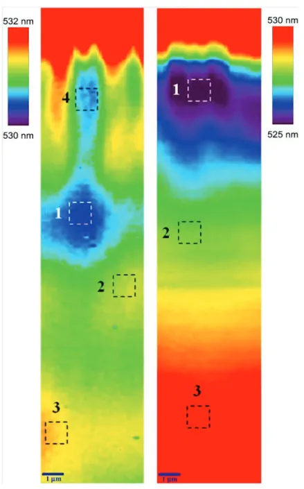
The spatial distributions of all the parameters were nearly homogeneous, except the center-of-mass distribution (Figure II.6). The spatial distributions in LSO:Ce and LGSO:Ce crystals are qualitatively different. In LSO:Ce the PL band gradually shifts to longer wavelength with increasing distance from the surface. This behavior can be explained by reabsorption due to fluctuations in Ce overall concentration in the regions
58
under study. Meanwhile, this feature is less pronounced in LGSO:Ce, probably, due to better homogeneity in overall Ce distribution. This assumption is supported by higher segregation coefficient (up to 0.8) in Lu0.5Gd1.5SiO5:Ce [43] compared to LSO:Ce (0.22) [83].
Figure II.6. Spatial distribution of PL band center-of-mass position in LGSO:Ce (left), LSO:Ce (right).
![Figure I.2. Photograph of the as-grown Lu 1.5 Y 1.5 Al 5 O 12 single crystal [42]](https://thumb-eu.123doks.com/thumbv2/123doknet/14668702.741325/18.892.170.705.237.784/figure-i-photograph-grown-lu-al-single-crystal.webp)
![Figure I.4. Transversal cut view of the 0.12 at.% LuAG:Ce fibers excited under X- X-rays (a) and electrons (b), presenting a distribution of Ce activator to the periphery of the fiber samples [7]](https://thumb-eu.123doks.com/thumbv2/123doknet/14668702.741325/21.892.91.803.87.439/figure-transversal-excited-electrons-presenting-distribution-activator-periphery.webp)
![Figure I.6. Excitation and emission spectra of GSO:Ce crystal at the room temperature [76]](https://thumb-eu.123doks.com/thumbv2/123doknet/14668702.741325/24.892.145.723.81.509/figure-excitation-emission-spectra-gso-crystal-room-temperature.webp)
![Figure I.9. The light output is shown as a function of the cerium concentration in LSO [15]](https://thumb-eu.123doks.com/thumbv2/123doknet/14668702.741325/27.892.87.774.82.433/figure-light-output-shown-function-cerium-concentration-lso.webp)

![Figure I.15. Schematic phase diagram for Gd 2 SiO 5 - Lu 2 SiO 5 solid-solutions [93]](https://thumb-eu.123doks.com/thumbv2/123doknet/14668702.741325/32.892.92.764.80.736/figure-schematic-phase-diagram-sio-sio-solid-solutions.webp)
![Figure I.20. Pulse height spectra of some LGSO:Ce and LGSO:Ce,Ca crystals in comparison with BGO and LSO:Ce [43]](https://thumb-eu.123doks.com/thumbv2/123doknet/14668702.741325/38.892.105.822.445.993/figure-pulse-height-spectra-lgso-lgso-crystals-comparison.webp)