HAL Id: tel-02174201
https://tel.archives-ouvertes.fr/tel-02174201
Submitted on 5 Jul 2019HAL is a multi-disciplinary open access archive for the deposit and dissemination of sci-entific research documents, whether they are pub-lished or not. The documents may come from teaching and research institutions in France or abroad, or from public or private research centers.
L’archive ouverte pluridisciplinaire HAL, est destinée au dépôt et à la diffusion de documents scientifiques de niveau recherche, publiés ou non, émanant des établissements d’enseignement et de recherche français ou étrangers, des laboratoires publics ou privés.
to relative humidity and clay content : experimental
study and constitutive modelling
Longfei Xu
To cite this version:
Longfei Xu. Mechanical behaviour of compacted earth with respect to relative humidity and clay content : experimental study and constitutive modelling. Mechanics of materials [physics.class-ph]. Université de Lyon, 2018. English. �NNT : 2018LYSET005�. �tel-02174201�
N°d’ordre NNT : 2018LYSET005
THESE de DOCTORAT DE L’UNIVERSITE DE LYON
opérée au sein de
École Nationale des Travaux Publics de l’Etat LGCB-LTDS UMR 5513
Ecole DoctoraleN° 162
MEGA (Mécanique, Energétique, Génie Civil, Acoustique) Spécialité : Génie Civil
Soutenue publiquement le 04/07/2018, par :
Longfei XU
Mechanical behaviour of compacted
earth with respect to relative humidity
and clay content: experimental study
and constitutive modelling
Devant le jury composé de :
Philippe COSENZA Professeur (Université de Poitiers) Président
Jean Michel PEREIRA Professeur (ENPC) Rapporteur
Philippe COSENZA Professeur (Université de Poitiers) Rapporteur
Mathilde MORVAN Maître de Conférences (UCA) Examinatrice
Annan ZHOU Senior Lectuer (RMIT) Examinateur
Henry Kwai Kwan WONG Directeur de Recherche CNRS (ENTPE) Directeur
Antonin FABBRI Chargé de Recherche (ENTPE) Co-directeur
III
This thesis is the result of four years of work whereby I have been accompanied and supported by many people. I take this opportunity to extend my sincere gratitude and appreciation to all those who made this PhD thesis possible.
Foremost, I would like to express my sincere gratitude to my thesis supervisor, Prof. Kwai Kwan WONG, for accepting me into his research group. I acknowledge his guidance and encouragement through this four years study, and his constant confidence in my abilities. He is always willing to share his experience and expertise throughout my PhD study. He taught me how to be a researcher and I will always be grateful for this. His advice on both research as well as on my career have been invaluable.
I would also wish to express my deep gratitude to my co-supervisor Dr. Antonin FABBRI for extended discussions and valuable suggestions which have contributed greatly to the thesis. His immense knowledge and his logical way of thinking have been of great value for me.
Special thanks to Dr. Florian Champiré for his contribution to the experimental apparatus and his unconditional help during the experiments. I admire his affirmative professional attitude, and his efficient mindful approach to simplify complexities. I enjoyed our collaboration and the good time we had together.
I appreciate Prof. Philippe COSENZA and Prof. Jean-Michel PEREIRA for the time they allocated to read my manuscript and for their precious reviews and comments. Further thanks are due to other thesis defense committee members: Dr. Mathilde MORVAN and Dr. Annan ZHOU. Also thanks to Prof. Rafael ANGULO-JARAMILLO for his presence in my thesis defence.
I am also grateful to a number of colleagues and friends for their assistance during my research in LGCB of ENTPE. I appreciate Dr. Denis BRANQUE, Dr. Fionn McGregor, Dr. Ali MESBAH and Dr. Hoang Ngoc LAN, for their precious advice and assistance on the experiments. I also warmly thank the technical staff from ENTPE, Mr. Stephane COINTET, Mr. Joachim BLANC GONNET, Mr. Frédéric SALLET and Mme. Nadia Bekkouche, for their help in my thesis.
In addition, I would like to thank to Mme. Marie-Claire HERVE TOUZE for her warm reception and patient help in my living on behalf of ENTPE. I would like to express my
IV
Then, I would like to say thank you to my Chinese friends here at Lyon who have made my life very enjoyable.
Finally, I dedicate this part to thank all my family for all their love and encouragement. A tough journey becomes easier when we travel together. At last, but not certainly least, I would like to give my most heartfelt thanks to my beloved wife Minghui ZHU and also my son Boang XU, for being my endless source of peace. To end, I am grateful again to my wife, for her unconditional support, her continual love and her encouragement that helped me along the difficult times. Her love is the greatest power in the world and has driven me to succeed in every goal I have dreamed of.
The present work has been supported by the French Research National Agency (ANR) through the‘‘Villes et Bâtiments Durables” program (Project Primaterre no. ANR-12-VBDU-0001). My living in FRANCE is supported by the China Scholarship Council (CSC) with a PhD Scholarship (FileNo.201406300070).
V
Compacted earth is regarded as a granular mixture in which clay plays a role of binder but also exhibits an important interaction with water. During its service period, compacted earth can be subject to large changes in relative humidity. Those perpetual changes of environmental conditions induce continuous changes of water content of the earth that impact significantly its mechanical performances. The present work aims at studying the mechanical behavior of compacted earth with respect to relative humidity and clay content. It involves an extensive experimental study and a constitutive modelling.
For clarity, the presentation of experimental results will be divided into two parts. In the first part, four kinds of local earth are identified with variety of clay content. A comparison of compaction method was then conducted between a double static compaction and dynamic compaction. Similarly to Proctor test, a series of iso-energy cures can be sought out during static compaction. And all the optimum points approximately lie on a specific saturation degree line regardless of the compaction method and compaction energy. Three types of specific tests: suction test by filter paper method, shrinkage test and sorption-desorption test were carried out on those samples from aforementioned compaction, thereby providing a preliminary insight on the effect of clay content and moisture content: the results reveal that matric suction increases with increasing clay content and decreasing moisture content. For a given earth, when the logarithm of suction values are plotted against moisture content, the results lie approximately on a unique line for all compaction methods. Comparing between different soils, a higher clay content results in a higher hygroscopic ability to absorb and store moisture from the surrounding air.
In the second part, the impact of clay content and moisture contents on the shear behavior of compacted earth was investigated taking into account loading-unloading cycles. Fine sand of different proportions was added into a natural soil thereby obtaining three different soils with clay contents respectively of 35%, 26% and 17%. A series of triaxial tests were conducted on samples previously equilibrated at three different values of relative humidity (23%, 75% and 97%). The confinement conditions are 0, 100, and 600kPa respectively. The evolution of failure strength fc, Young's modulus E and residual strain Ԑres with clay content and RH was investigated, the last two parameters being measured during loading-unloading cycles. The first important observation is that the relative humidity at which samples were fabricated and conditioned has a strong impact on the mechanical characteristics of earthen material: an
VI
Secondly, with increasing stress level, a progressive degradation of Young’s modulus as well as an increase of residual strain Ԑres (after a loading-unloading cycle) appear. Thirdly, within the range of clay contents investigated, both the failure strength fc and residual strain Ԑres increase with increasing clay content at constant RH and confining pressure, the rate of this increase being a function of RH. Young’s modulus E is relatively insensitive to changes in clay content, its variation being less than 20% for all cases. Finally, based on a particular definition of Bishop's effective stress involving a specific functional form χ(s), failure states of all samples were observed to lie approximately on a unique failure line crossing the origin in the (p'-q) plane regardless of matric suction and confining pressure.
Finally, based on the above experimental results, a new constitutive model was proposed aiming to simulate mechanical behaviour of compacted earth. This model accounts for stiffness degradation using the approach of continuum damage mechanics. The poroplastic behaviour is modelled based on the Bounding Surface Plasticity (BSP) theory and the concept of effective stress, while isotropic damage is modelled using a scalar variable. Plastic flow and damage evolution occur simulataneously in a coupled process, taking into account the impact of suction. The model was successfully validated against results of triaxial compression tests performed at different relative humidities and confining pressures. Despite the relatively small number of material parameters, this model can reproduce the essential features of earthen materials behaviour observed experimentally: suction-induced hardening and stiffening, post-peak softening, as well as the progressive transition from contractant to dilatant volumetric behaviour. Use of the BSP theory allows to reproduce a smooth stress-strain relation as experimentally observed, instead of an abrupt change upon plastic yielding predicted by classic elastoplastic models. Furthermore, the present model also furnishes a quantitative description on the degradation of elastic properties hitherto not accounted for, thanks to the additional scalar damage variable.
Keywords: Compacted earth, clay content, relative humidity, loading-unloading, failure criterion, bounding surface plasticity; damage; degradation
VII
Chapter 1 Introduction ... 1
1.1 Earth building materials ... 2
1.1.1 Wattle and daub ... 4
1.1.2 Adobe and compressed earth blocks (CEB) ... 4
1.1.3 Cob ... 5
1.1.4 Rammed earth ... 6
1.1.5 Cave dwelling - Chinese Yaodong ... 9
1.2 Advantages and limitations of earth materials ... 10
1.2.1 A sustainable construction material ... 10
1.2.2 Limitation and vulnerability of earth material ... 13
1.3 Research objectives ... 14
1.4 Thesis layout ... 15
Chapter 2 Overview of earth mechanical behaviour: experimental investigation and modelling development ... 17
2.1 Experimental investigation on the mechanical behaviour of earthen materials ... 18
2.1.1 Sample geometry ... 18
2.1.2 Dry density ... 20
2.1.3 Clay minerals, effect of clay content on mechanical behaviour ... 22
2.1.4 Suction and its influence on earth mechanical behaviour ... 27
2.2 Modelling development of earthen materials ... 33
2.2.1 Damage models ... 34
2.2.2 Elastoplasticity model ... 36
2.2.3 Coupling between damage and elastoplasticity ... 38
Chapter 3 Characterisation of local earthen materials ... 39
3.1 Overview of crude earthen materials ... 40
VIII
3.2.2 Plasticity property ... 46
3.2.3 Methylene blue value ... 48
3.3 An exploration of the optimum state based on dynamic compaction (Proctor test) and double static compaction ... 51
3.3.1 Motivation of this exploration ... 51
3.3.2 Dynamic compaction (Proctor test) ... 52
3.3.3 Double static compaction ... 56
3.3.4 Comparison between dynamic compaction and static compaction ... 63
3.4 Specimen’s suction at fabrication stage ... 65
3.4.1 Basic concepts and measurement techniques ... 65
3.4.2 Procedures for suction measurement ... 67
3.4.3 Results and discussion ... 69
3.5 Shrinkage test ... 72
3.5.1 Test procedures and apparatus ... 73
3.5.2 Results and discussion ... 74
3.6 Isothermal sorption-desorption test ... 77
3.6.1 Desiccator method ... 78
3.6.2 DVS (dynamic vapor sorption) method ... 80
3.7 Conclusion ... 82
Chapter 4 Loading-unloading shear behaviour of compacted earth with respect to clay content and relative humidity ... 83
4.1 Introduction and research motivation ... 84
4.2 Materials and methods ... 85
4.2.1 Lim and two artificial earthen materials ... 85
4.2.2 Sample preparation ... 87
4.2.3 Experimental apparatus ... 88
IX
4.3.1 Experimental repeatability ... 91
4.3.2 Influence of relative humidity on loading-unloading shear behaviour ... 92
4.3.3 Influence of clay content on loading-unloading shear behaviour ... 98
4.3.4 Influence of stress level on the mechanical behavior ... 101
4.4 Discussion ... 102
4.4.1 Generalized effective stress approach ... 102
4.4.2 Determination of the effective stress parameter χ ... 103
4.5 Conclusion ... 107
Chapter 5 A poro-elastoplastic damageable constitutive model for compacted earth .. 108
5.1 Introduction ... 109
5.2 A poro-elastoplastoplastic damageable constitutive model ... 109
5.2.1 Partial saturation and effective stress ... 109
5.2.2 General concept of Bounding Surface Plasticity ... 112
5.2.3 Plastic and non-plastic mecanisms considering damage variable D. ... 113
5.2.4 Damage mechanism ... 117
5.2.5 Elastoplastic Compliance matrix accounting for damage ... 119
5.3 Model validation against experimental data and discussion ... 119
5.3.1 Determination of model parameters ... 119
5.3.2 Model implementation ... 120
5.3.3 Stress-strain behaviour and volumetric evolution ... 121
5.3.4 Degradation of elastic property ... 126
5.4 Conclusion ... 127
Chapter 6 Conclusion and perspective ... 128
6.1 General conclusion ... 129
6.1.1 Local raw earth materials ... 129
X
6.2 Perspectives ... 132 Appendix ... 133 References ... 138
XI
Figure 1.1 Earthen constructions around the world ... 3 Figure 1.2 Classification for the earth construction techniques (Wm =manufacture water content, Wop = optimum Proctor water content; WP = water content at plasticlimit; WL = water content at liquid limit) ... 3 Figure 1.3 (a) construction process using wattle and daub technique (b) house made of wattle and daub in Colmar France ... 4 Figure 1.4 (a) adobe bricks manufacture process (b) house construction using adobe bricks .. 5 Figure 1.5(a) CEB manufacture process manually (b)house built with CEB in Rhone-Alpes France ... 5 Figure 1.6 (a) a wall under construction with cob (b) a house using cob technique in ... 6 Figure 1.7 (a) Traditional wood formwork (b) metallic one used in the laboratory ENTPE Lyon ... 7 Figure 1.8 Regions of using rammed earth in France (Pignal 2005) ... 8 Figure 1.9 Prefabricated rammed earth wall used to build Ricola’s factory in Switzerland ... 9 Figure 1.10 (a) Yaodong dig in the cliff on the edge of the loess slopes (b) Yaodongs built into "sunken courtyard" ... 10 Figure 1.11 comparison of temperature buffering between inside and outside of an earth house (Soudani 2017). ... 12 Figure 2.1 Three scales for rammed earth studied by Bui et al. (2009) ... 19 Figure 2.2 Compaction curves and variation of compressive strength with water content and ... 20 Figure 2.3 Variation of compressive strength with dry density (Morel et al. 2007) ... 21 Figure 2.4 Variation of adobe compressive strength and Young’s modulus with dry density 22 Figure 2.5 Schematic representation of microstructure units of clay minerals (Modified after CHAMPIRE (2017)) ... 23 Figure 2.6 Schematic representation of clay soil structures at macroscopic and
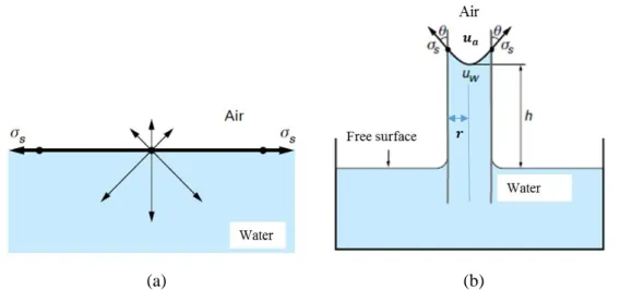
microstructural level (Modified after Lei (2015)) ... 25 Figure 2.7 Variation of shrinkage and bending strength with clay content ... 26 Figure 2.8 Variation of adobe compressive strength and Young’s modulus with dry density 27 Figure 2.9 Schematic representation of clay thread zone (Kim et al. 2016) ... 27 Figure 2.10 Schematic illustration of (a) surface tension at the gas-liquid interface (b) matric suction generated by meniscus concave on the air side ... 28
XII
Figure 2.13 Evolution of Young’s modulus E versus stress level at different relative
humidities and confining pressure (Xu et al. 2017) ... 32
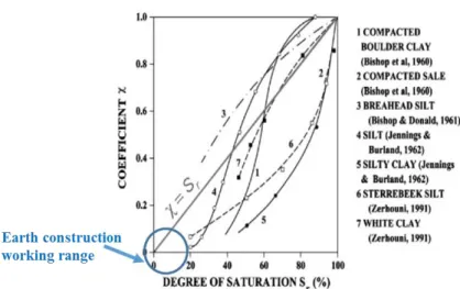
Figure 2.14 Evolution of effective stress parameter with degree of saturation ... 33
Figure 2.15 Comparison between experiments and simulations of uniaxial compression test 35 Figure 2.16 Comparison between experimental results and model predictions using a non-linear elastic perfectly plastic model (Gerard et al.2015) ... 36
Figure 2.17 Schematic representation of bounding surface plasticity and the radial mapping method ... 37
Figure 3.1 Location of the crude eath in this study ... 40
Figure 3.2 Existing earth buildings in four villages from Rhone-Alpes region ... 41
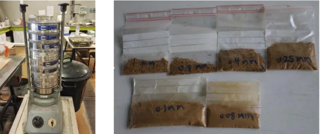
Figure 3.3 Experimental sieves and the retained fractions in wet sieving method ... 43
Figure 3.4 Experimental procedure and apparatus for sedimentation test ... 44
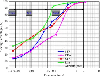
Figure 3.5 Particle Size Distribution of four crude earthen materials and maximum and minimum grain size distribution of soil recommended by (AFNOR 2001). ... 45
Figure 3.6 Casagrande apparatus and 3 mm diameter rolls without cracking ... 46
Figure 3.7 Plastic index 𝐼𝑃 versus clay content ... 47
Figure 3.8 Plastic 𝐼𝑃 against liquid limit and the recommended region proposed by (AFNOR 2001) ... 47
Figure 3.9 Schematic outcome for methylene blue test (a) blue stain surrounded by a colourless wet area; (b) blue stain surrounded by a light blue halo (Chiappone et al. 2004) .. 49
Figure 3.10 Experimental procedure and apparatus for methylene blue value test... 49
Figure 3.11 Blue activity diagram (Lautrin 1989). Classes as follows: 1. not clayey soil; 2. soil with interactive clay fraction; 3. soil with not much active clay fraction; 4. soil with normal clay fraction; 5. soil with active clay fraction; 6. soil with very active clay fraction; 7. soil with noxious clay fraction. ... 50
Figure 3.12 Pneumatic compactor system and illustration of normal, modified Proctor test . 53 Figure 3.13 Prepared soil with different moisture contents and compacted sample ... 55
Figure 3.14 Variation of dry density with respect moisture content using ... 56
Figure 3.15 Evolution of dry density versus moisture content for STA under three kinds of compacted energy ... 56
XIII
Figure 3.18 Compaction curves illustrated speed vs time and force against time ... 59
Figure 3.19 (a)Distribution of specimens’ height stated on CRA (b) Distribution of dry density along with the position in the direction of specimen’s height for CRA (CHAMPIRE 2017) ... 60
Figure 3.20 (a)Experimental set-up (b) Compacted specimens wrapped with filter paper ... 61
Figure 3.21 Static compaction curves for CRA (w=4.5%) under different dry densities ... 61
Figure 3.22 Dry density versus moisture content for CRA ... 63
Figure 3.23 Dry density versus moisture content for STR ... 64
Figure 3.24 Repeating Proctor test points using static compaction and the corresponding energy ... 65
Figure 3.25 Calibration Suction-Water Content Curves for Wetting of ... 67
Figure 3.26 Filter paper arrangements for different types of samples ... 68
Figure 3.27 Experimental procedures for suction measurement ... 68
Figure 3.28 Variation of suction following water content for samples from modified Proctor test ... 69
Figure 3.29 Variation of suction following water content for samples from static compaction ... 70
Figure 3.30 Comparison of measured suction for CRA using filter paper from different sources ... 70
Figure 3.31 Influence of compaction energy on the evolution of suction ... 71
Figure 3.32 Variation of suction versus dry density for CRA samples from static compaction ... 71
Figure 3.33 Variation of suction versus dry density for STR samples from static compaction ... 72
Figure 3.34 Experimental set-up and thermostatic condition for the quasi-continuous shrinkage test ... 74
Figure 3.35 Water content evolution against time for STR: a. series with different initial fabricated water content b. series with various compacted dry density ... 74
Figure 3.36 Water content evolution against time for CRA: a. series with different initial fabricated water content b. series with various compacted dry density ... 75
Figure 3.37 Vertical shrinkage strain results for STR: a. series with different initial water content at fabrication b. series with various compacted dry density ... 75
XIV
Figure 3.39 Schematic diagram for the typical shrinkage curve with four shrinkage zones .. 76 Figure 3.40 Shrinkage curves plotting void ratio versus moisture ratio for STR and CRA ... 77 Figure 3.41 Schematic diagram of selected points for isothermal sorption-desorption tests .. 78 Figure 3.42 Experimental apparatus and samples for isothermal sorption-desorption test ... 79 Figure 3.43 Sorption-desorption curves for three earthen materials using desiccator method 80 Figure 3.44 Sorption-desorption curves for STR and CRA at different state (dry, wet and optimum) ... 80 Figure 3.45 Comparison between the sorption curves obtained with the DVS and with the desiccator method for Lim ... 81 Figure 4.1 Particle size distributions of Lim, Mix1, Mix2 and fine sand ... 86 Figure 4.2 Sorption-desorption curves for three soils using DVS method ... 86 Figure 4.3 Fabricated samples and their conditioning process using saturated salt solutions 87 Figure 4.4 Home designed experimental apparatus for loading-unloading triaxial tests ... 89 Figure 4.5 Schematic diagram of two types of mechanical loadings ... 90 Figure 4.6 Schematic diagram of experimental arrangement considering various impact factors ... 91 Figure 4.7 Evolution of deviator stress (a) and volumetric strain (b) versus axial strain during loading and unloading for Mix1 at 75% RH, 100 kPa confining pressure ... 92 Figure 4.8 Stress–strain behavior at given relative humidity and 100 kPa confining pressure for ... 93 Figure 4.9 Volumetric evolution versus axial strain at given relative humidity and 100 kPa confining pressure for Mix1, Mix2 and Lim ... 94 Figure 4.10 Failure strength of Mix1, Mix2 and Lim as a function of relative humidity under different confinement conditions ... 96
Figure 4.11 Evolution of Young’s modulus E through “20% of fc” cycle for Mix1, Mix2 and
Lim under different confinement conditions ... 97
Figure 4.12 Evolution of residual strain Ԑres through “20% of fc” loading-unloading cycle for
Mix1, Mix2, Lim under different confinement condition ... 98 Figure 4.13 Failure strength as a function of clay content under different confinement
conditions ... 99 Figure 4.14 Young’s modulus E as a function of clay content under different confinement conditions and relative humidity ... 100
XV
Figure 4.16 Evolution of Young’s modulus E and residual strain versus stress level at
different relative humidity and 100 kPa confining pressure for Mix1 ... 102
Figure 4.17 Translation from mean stress (p-q) plane to effective stress (p'-q) plane ... 103
Figure 4.18 Relationships between ln(𝜒) and ln𝑠for three types of soil ... 104
Figure 4.19 Variation of air-entry suction with changing clay content ... 105
Figure 4.20 (p-q) plane and (𝑝′-q) plane under different suctions and confining pressures using Eq. (4-7) for three soils ... 106
Figure 5.1 Failure states for Lim at different suctions and confining pressures before and after the translation using Eq. (5-3) and Eq. (5-4), demonstrating the unique failure line in the (𝑝′-q) plane ... 111
Figure 5.2 Bounding surface, Loading surface, and the radial mapping method ... 112
Figure 5.3 Bounding surface on the response of parameter: (a) n and (b) r ... 114
Figure 5.4 Triaxial compression tests on Lim at three different hydraulic states at 100 kPa confining pressure: (a) 𝑞-𝜀1 plot and (b) 𝜀𝑣-𝜀1 plot. ... 121
Figure 5.5 Triaxial compression tests on Lim at three different hydraulic states at 600 kPa confining pressure: (a) 𝑞-𝜀1 plot and (b) 𝜀𝑣-𝜀1 plot. ... 123
Figure 5.6 Triaxial compression tests on Mix1 at three different hydraulic states at 100 kPa confining pressure: (a) 𝑞-𝜀1 plot and (b) 𝜀𝑣-𝜀1 plot. ... 124
Figure 5.7 Triaxial compression tests on Mix1 at three different hydraulic states at 600 kPa confining pressure: (a) 𝑞-𝜀1 plot and (b) 𝜀𝑣-𝜀1 plot. ... 125
Figure 5.8 Evolutions of Young’s modulus versus radial strain during triaxial tests on Mix1 at confining pressure of 100 kPa. (a) RH=75% (b) RH=97% ... 126
Figure 5.9 Influence of 𝑘3on the stress-strain behaviour for Mix1 at 75% RH and 100 kPa confining pressure ... 127
Figure A.1 Stress–strain behavior at given relative humidity and 0 kPa confining pressure for ... 134
Figure A.2 Volumetric evolution versus axial strain at given relative humidity and 0 kPa confining pressure for Mix1, Mix2 and Lim ... 135
Figure A.3 Stress–strain behavior at given relative humidity and 600 kPa confining pressure for ... 136
Figure A.4 Volumetric evolution versus axial strain at given relative humidity and 600 kPa confining pressure for Mix1, Mix2 and Lim ... 137
XVI
Table 1.1 Energy consumption for different construction types (J. C. Morel et al. 2001) ... 11
Table 2.1 Summarization of the sample geometry and their mechanical properties in literatures ... 19
Table 2.2 Summarization of characteristic for the selected earth(Champiré et al. 2016a) ... 31
Table 2.3 Failure strength fc (Mpa) at different test conditions for earth CRA ... 32
Table 3.1 Grain Size of soils considered in this study... 44
Table 3.2 Plasticity properties of four crude earthen materials ... 47
Table 3.3 Methylene blue value results and an evaluation of clay contained in earth ... 50
Table 3.4 Parameters and calculated energy for different kinds of Proctor test using CBR mould ... 54
Table 3.5 Characteristics of compacted specimens for CRA ... 62
Table 3.6 Characteristics of compacted specimens for STR ... 63
Table 3.7 Summary of suction measurement methods (Hu, Yang, and Li 2010) ... 66
Table 3.8 Summary of RH values for the selected saturated salt solutions at 23° C ... 79
Table 4.1 Suction imposed by means of the different saturated saline solutions at 23 °C ... 88
Table 4.2 Coefficient values in χ-s function for three soils ... 105
XVII
Roman symbols
𝐴𝐶𝐵 index of clay activity
𝑐ℳ molar concentration of the electrolyte
𝐷 damage variable
𝑒 void ratio
𝑒0 initial void ratio
𝐸 young’s modulus 𝑓𝑐 failure strength 𝐹 bounding surface 𝑓 loading furface 𝑓𝐷 damage criterion 𝐻 plastic modulus
𝐻𝑏 plastic modulus on bounding surface
𝐻𝛿 additive plastic modulus
h Constant to calibrate the hardening modulus
𝐼𝑃 plastic index
𝑘1 Constant to control suction effects on the hardening
parameter
𝑘2 Constant to control suction effects on volumetric
compressibility
𝑘3 Constant to describes the damage evolution
𝑙 suction-hardening function
𝑀𝑤 molar mass of water
mdry dry sample mass
mwet wet sample mass
𝑚𝑑105°C dry mass in an oven at 105 °C
𝑚𝑑23°C dry mass through a flow of dry air at 23 °C
mR retained friction mass
mP passed fraction mass
𝒎 unit vector of plastic potential
m Constant to define plastic potential
XVIII
𝐧 unit vector for the BS
n Constant specify the shape of bouning surface
𝑝𝜋 preconsolidation pressure
p mean stress
p' mean effective stress on loading surface
𝑝̅′ mean effective stress on bounding surface
𝑞̅ deviatoric stress on bounding surface
q deviatoric stress on loading surface
R universal gas constant
r Space ratio 𝑠 total suction 𝑠𝑚 matric suction 𝑠𝑜 osmotic suction 𝑆𝑟 degree of saturation 𝑠𝑒 air-entry suction
𝑢𝑎 pore air pressure
𝑢𝑤 pore water pressure
𝑉𝑉 volume of pore
𝑉𝑤 volume of pore water
𝑉𝑠 volume of solid
𝑉𝐵 blue value of the soil
𝑊𝐿 liquid limit
𝑊𝑃 plastic limit
𝑤𝑖𝑛𝑡 initial water contents
𝑤𝐷𝑉𝑆 water contents in DVS
𝑤𝐷𝑉𝑆𝐶𝑜𝑟𝑟𝑒𝑐𝑡𝑒𝑑 water contents in DVS after correction
𝑌𝐷 damage force
Greek symbols
𝛼 Constant to define effective stress parameter
XIX
ℂ elastoplastic compliance matrix accounting for damage
𝜀𝑖 principle strain (i=1,2,3)
𝜀𝑖+ tensile part of the principal strain
𝜺 Total strain
𝜺𝒆 elastic strain
𝜺𝒑 plastic strain
𝜀𝑣 volumetric strain
𝜀𝑞 deviatoric strain
𝜀𝑣𝑒 elastic volumetric strain
𝜀𝑞𝑒 elastic deviatoric strain
𝜀𝑣𝑝 plastic volumetric strain
𝜀𝑞𝑝 plastic deviatoric strain
𝜀𝑟𝑒𝑠 residual strain
Δ𝜀𝑥𝑥𝑐𝑦𝑐𝑙𝑒 differences of the axial strain between the maximal and minimal
𝜂 stress ratio
𝜃 contact angle between the water and the boundary
𝜅 Slope of unloading line in the e -lnp′ space
𝜆 plastic multiplier
𝜆0 Volumetric compressibility constant
𝜈 Poisson's ratio
𝜗 moisture ratio
𝜌𝑤 bulk density of water
𝜌𝑑 dry density
𝜌𝑠 soil grain density
𝜎𝑠 tensile force per unit length of interface
𝜎𝑖 principle stress (i=1,2,3)
𝜎0 reference stress for dimensionless
𝝈′ current stress point
𝝈̅′ image stress point on BS
Δ𝜎𝑥𝑥𝑐𝑦𝑐𝑙𝑒 differences of the axial stress between the maximal and minimal
XX
𝜒 effective stress parameter
𝛹 total water potential
𝛹𝑔 gravitational potential
𝛹𝑝 gas pressure potential
𝛹𝑚 matric potential
𝛹𝑜 osmotic potential
Operators
𝛿𝑖𝑗 Kronecker delta type function
∇̃ pseudo-gradient operator
‖. ‖ classic Euclidean norm of a vector
𝜕(. )
𝜕𝑥 partial derivative with respect to a variable x
1
Chapter 1
Introduction
2
1.1 Earth building materials
An earth building contains a significant part of unfired soil in their structure and/or building fabric. Earthen buildings can be constructed using several technics, e.g. rammed earth or compressed earth block (Hall et al. 2012). Earth constructions have a long history in the process of human civilization. According to the archaeological excavations, the first use of earth as building material dates back to the Neolithic period in approximately 10 000 BC from the eastern Mediterranean and Mesopotamia (Schroeder 2012). Earth material then became more and more popular in buildings considering its excellent performance in terms of structural stability, durability and environmental comfort. It is also quite adaptable, being used for footings, floors, walls and roofs utilising many techniques. Nowadays, one third of the world population lives in earthen houses and this number reaches more than one half in developing countries (Minke 2009). A great number of earth constructions, from rural habitats to impressive military citadels, can be found all over the world (shown in Figure 1.1), e.g. in Europe (France, Spain, Portugal and Italy etc.), the Africa region (Morocco, Algeria), South America (Mexico, Peru, Brazil) and the Asia area (China and Iran).
(a) Wattle and daub constructions, Lyon, France
(b) Rammed earth house Rhone-Alpes, France
(c) Roofs with plaster decorated acroterions, Libya
3
(f) Bam, Iran (g) Pyramid of the Sun, Mexico Figure 1.1 Earthen constructions around the world
There are a great varieties of earth building constructions: the earth has been providing various soil compositions at different places and the construction techniques have been evolving for hundreds of years. Each technique differs from the composition of the soil used, the compaction method, the initial moisture in the material and the drying process ( Soudani 2017). In addition, earth buildings are related to human ecology and include contemporary as well as historical and vernacular examples drawn from many cultures and periods (Niroumand et al. 2013).
The techniques principally used are described in Figure 1.2, adapted from the classification proposed by Hamard (2018). Herein, a special cave-dwellings dug in original earth (mainly distributed in north-west of China and called “Yaodong” in chinese) is supplemented in this classification.
Figure 1.2 Classification for the earth construction techniques (Wm =manufacture water content, Wop = optimum Proctor water content; WP = water content at plastic limit; WL = water content at
4
1.1.1 Wattle and daub
Wattle and daub is perhaps the oldest earth-building technologies in the world. This technique consists of two parts, wattle and daub: a wattle is a woven structure of small plant elements held together in a stiff frame; common materials used to create wattle are reeds, bamboo, branches and twigs. Daub or mud adheres to the irregularities and overhangs of the organic matrix. The daub is then smeared on to the wattle by hand until the entire surface is covered. After drying, either the finish surface can be a smooth final coat of daub, or it can be whitewashed with lime. This technique is for the construction of non–loading bearing walls, either partition walls or external walls, with widths between 8 cm and 20 cm. It is the wattle who holds the bearing capacity rather than the earth, and the wattle (woven structure) is highly earthquake resistant because it is extremely flexible. This is the reason why wattle and daub is often used in seismic zones throughout the world such as South America and Indonesia(Niroumand et al. 2013). Figure 1.3 (a) presents the construction process using wattle and daub technique, Figure 1.3 (b) shows a house made of wattle and daub in Colmar France.
Figure 1.3 (a) construction process using wattle and daub technique (b) house made of wattle and daub in Colmar France
1.1.2 Adobe and compressed earth blocks (CEB)
Adobe is also an ancient construction technique involving pouring a wet mixture of clay soil into parallelepiped moulds with dimensions of conventional bricks; the wet soil can also be mixed with organic fibres. After this, the adobes are left in the sun to dry for several days and then used to build masonry structures likewise ordinary fired bricks. Stabilizing agents such as mud and mortar are used for manufacturing adobe bricks. Other additives like asphalt emulsion, lime and cement have also been used in mud bricks and walls. It is worth noting adobe bricks have offered simple structural solutions for structures such as vaults, arches and domes, which
5
are impossible to construct with rammed earth. Manufacture process for this type of technique is shown in Figure 1.4.
Figure 1.4 (a) adobe bricks manufacture process (b) house construction using adobe bricks
CEB (compressed earth blocks) technique is often considered to be an improved form in modern earth buildings compared to adobe in traditional earth construction. This method consists of using specific presses to compact moist soil to a relatively high density inside a mould. The pressure can be applied manually or mechanically (Figure 1.5(a)). Blocks are subsequently assembled as masonry structures without mortar but with a thin joint of mud slurry to compensate surface roughness and enhance airtightness. Figure 1.5(b) shows an example for apartments in France made of CEB blocks.
Figure 1.5(a) CEB manufacture process manually (b)house built with CEB in Rhone-Alpes France
1.1.3 Cob
Cob seems to be the simplest one of all earth-building technologies. This technique makes use of very few tools and no formwork or internal structure and consists of piling and molding mud to create walls. For this type of construction, the earth is moderately wetted and is often mixed with organic fibres (e.g. straw, reed or heath) which helps the mud hold its form as it is piled. Mud is shaped using trowel or hand and is placed directly in top of a structure. Since cob is
a b
6
implemented at plastic state, its mechanical resistance is low and the material subsides under its own weight during construction process. The height of wall done in a same time was limited. As a result, cob walls were a superimposition of successive monolithic earth raised, called lifts (Fodde 2009; Forster et al. 2008). The height of a lift varied with soil type, plasticity and stress applied on the wall during construction. Lift heights ranged from 10 to 120 cm with an average of 59 cm. Wall thicknesses ranged from 10 to 150 cm with an average of 62 cm. A new lift was realized when the previous one was dry enough (about two weeks depending on the climate) to bear the weight of the new lift without deforming. Cob building is therefore time-consuming, but highly sculptural and offers the flexibility of producing walls of variable shapes (e.g. non-rectilinear walls). Because of its simple nature, cob construction has become very common in the whole world. A wall under construction is illustrated in Figure 1.6 (a), meanwhile a house using cob technique in Ille-et-Vilaine (France) is also shown in Figure 1.6 (b).
As the cob material dried, it shrunk and shrinkage cracks could expand inside the lift. If this expansion was too large, this could lead to structural damages. Shrinkage rates depended on clay content and manufacture water content of cob mixtures, high clay content and high manufacture water content leading to high shrinkage rate. Hence, the technique requires a careful selection of materials and construction detailing.
Figure 1.6 (a) a wall under construction with cob (b) a house using cob technique in Ille-et-Vilaine France
1.1.4 Rammed earth
Rammed earth is a building technique involving in compressing a moist earth mixture layers by layers within the formwork. It is an ancient method that has been revived recently as a sustainable building technique used in modern earth buildings.
Manufacture of rammed earth
7
Rammed earth is always used for constructing foundations, floors, and walls. The construction of an entire rammed earth wall begins with a temporary frame, denominated the "formwork". In traditional construction, the formwork is usually made of wood or plywood (in Figure 1.7(a)), and plays a role of mould, ensuring desired shape and dimensions of each section of wall. The formwork must be durable and well braced, and the two opposing faces must be clamped together to prevent bulging or deformation caused by the large compressing forces. Nowadays, metallic shutters are being used, which allows a higher compaction energy (illustrated in Figure 1.7(b)).
Figure 1.7 (a) Traditional wood formwork (b) metallic one used in the laboratory ENTPE Lyon
Moist earth is then poured into the formwork to a depth of 10 to 25 cm and compacted to approximately 50% of its original height. The material is compressed iteratively, in batches or courses, so as to gradually erect the wall up to the top of the formwork. Tamping was historically manual with a long ramming pole, and was very laborious, but modern construction can be made less so by employing pneumatically powered rammers.
When rammed earth wall is complete, it is sufficiently strong to immediately remove the formwork. This is necessary if a surface texture is to be applied, e.g., by wire brushing, carving, or mold impression, because the walls become too hard to work after approximately one hour. Construction is optimally done in warm weather so that the walls can dry and harden. The compression strength of the rammed earth increases as it cures; some time is necessary for it to dry and as long as two years can be necessary for complete curing.
Widespread use of rammed earth
A large number of beautiful and well-known construction wonders have been built through rammed earth. Examples of such great architectures include the Alhambra in Spain, the great Kasbahs of Morocco and the long stretches of the Great Wall of China. China has evidences of some of the most previous works built from rammed earth, where archaeologists discovered walls made of rammed earth back from the Longshan Culture of the Late Neolithic period
8
(between 2600 and 1900 B.C.E), the period between the Stone Age and the Bronze Age, a period when many cities in China were established. In the Fuijan province of central China, the round houses of the Hakka people have recently been given "World Heritage Site" status. These large rammed earth buildings, called Tulou (literally earth structures) are defensive homes to many families and can be up to 73.4 m across and four storeys high. The oldest of these buildings was built in 1308 and their construction continued well into the 20th century. This technology of building structures using rammed earth later spread throughout the Middle East. The Phoenician trading empire was the one that introduced the technology in Europe. The Romans spread the technology to southern France through the Rhone River valley, where they built the capital city, Gaul, which is called Lyon today (Capital of Rhone region).
In France, rammed earth structures are widespread especially in the Rhone-Alpes region where they represent around 40% of rural architectural heritage (Collectif FFB 2012). A lot of agricultural buildings and houses made of rammed earth date to more than 300 years and many are still inhabited, exhibiting excellent performance in terms of structural stability, durability and environmental comfort.
Figure 1.8 Regions of using rammed earth in France (Pignal 2005)
Currently, this construction method is becoming more popular because it meets the requirement of sustainable development. Rammed earth walls offer healthy indoor environments coupled with energy efficiency, long-life durability with low maintenance, as well as improved acoustics, improved seismic stability and fire barriers.
9
Rammed earth can be divided into two categories: unstabilised rammed earth” and “stabilised rammed earth”. The former is composed of clay, silt, and sand where clay acts as a binder between the grains (Q. B. Bui et al. 2011); while in “stabilised rammed earth”, chemical binders, such as cement and lime, are added into the soil for increasing inter-granular bonds and enhancing macroscopic strength. Besides, stabilization also limits the sensitivity of earth to erosion. Hence, a large number of modern rammed earth houses were stabilized with lime or cement, particularly in Anglo-Saxon countries such as Australia, USA or India, where the proportions ranges from 6% to 15% (Maniatidis and Walker 2003). However, using stabiliser leads to the reduction of the permeability of soils and thus the natural ability of earth to allow moisture to pass. The stabilization of rammed earth greatly increases the cost of construction and the recycling of the material becomes very difficult. Many studies have shown that stabilized rammed earth increases the embodied energy (T. T. Bui et al. 2014; Venkatarama Reddy and Prasanna Kumar 2010).
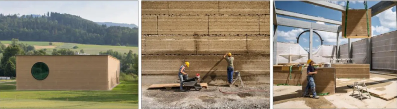
Another modern practice consists in the prefabrication of rammed earth walls. The prefabricated earth walls are normally produced in large molds, then brought to the construction site to be put together. The pre-fabrication of these panels can be produced either on-site or in workshops. An example of a building constructed with pre-fabricated walls in Switzerland is presented in Figure 1.9.
Figure 1.9 Prefabricated rammed earth wall used to build Ricola’s factory in Switzerland
1.1.5 Cave dwelling - Chinese Yaodong
Yaodong is a particular form of earth cave dwelling usually carved out of a hillside or excavated horizontally from a central "sunken courtyard" (Liu et al. 2005). This kind of earth structures make good use of structural strength of undisturbed soil. Yaodongs are commonly found in the north central provinces of China such as Shanxi, Shaanxi, Gansu and Henan, which are located on the Loess Plateau.It has been claimed that the use of Yaodongs can be dated back to the Qin
10
dynasty in the third century B.C. Over two millennia later, Yaodongs are still a popular choice of dwelling for those living on the Loess Plateau, as it is estimated about 40 million inhabitants of the Loess Plateau are still living in such structures.
Yaodong can be divided into different types, depending on the topography of the regions in which they were built. For instance, where hills are available, Yaodongs may be built into the slopes, and a hill may contain several stories of Yaodongs (illustrated in Figure 1.10 (a)). Where hills are not available, Yaodongs are simply built into the ground. Rectangular wells about 5 meters to 8 meters deep are first dug into the ground. After that, Yaodongs are built into the walls of these wells. The wells serve as a "sunken courtyard" for the inhabitants (Figure 1.10 (b)).
Figure 1.10 (a) Yaodong dig in the cliff on the edge of the loess slopes (b) Yaodongs built
into "sunken courtyard"
The continuous use of Yaodongs on the Loess Plateau over the millennia can perhaps be attributed to its highly economical and efficient design. In terms of building material, only the local loess soil from the plateau is required for the building of the Yaodongs. Loess soil is the obvious choice of material as it is easily available in the area, as opposed to wood or stone. Additionally, loess soil is a good insulator of heat. The thick earthen walls are able to keep the interior of the Yaodongs cool during the summer and warm during the winter (Zhu et al. 2014). Nevertheless, despite the advantages of the Yaodong cave dwellings, they do have one significant disadvantage-they are highly susceptible to destruction from natural disasters
1.2 Advantages and limitations of earth materials
1.2.1 A sustainable construction material
The construction industry creates a litany of environmental impacts, partly due to its large consumption of energy (Hendrickson and Horvath 2000). According to the statistics, the building sector accounts for about 40% of the generation of greenhouse gases; moreover,
11
construction is also responsible for high levels of pollution and produces a large amount of waste. It is reported that around 44% of the wastes collected in France come from the building industry (ADEME 2015).
In the context of sustainable development, more acute problems are related to energy and wastes and all sectors are working to reduce the environmental impact of their activities, which triggered new interest in alternative building materials with environmentally friendly characteristics. Among these, earth is one of the most attractive options because it can help reducing the energy consumption of the building sector. These materials are extracted directly on the construction site (or near the site) like raw soil and then transformed into construction material with a very low manufacturing energy. Earth is also recyclable, inexhaustible and, when properly manufactured, offers high strength, excellent hygro-thermal properties and low embodied energy at very low costs. Because of these attributes, earthen materials can dramatically reduce exploitation of natural resources not only during construction, but also during service life, by cutting down on heating/air conditioning needs, and at the end of life, by limiting demolition waste. The advantages of earth as a building material are summarized below:
Reduction of embodied energy-construction stage
As a kind of local non-industrial materials, raw earth is extracted directly on the construction site or near the site. Afterwards, implementation is conducted using manual and/or mechanized means. The recourse to mechanized means and possible transportation of earth increases the embodied energy of buildings. However, the embodied energy of modern unstabilized earth construction remains very low in comparison to other materials conventionally used in construction. Table 1.1 presents a comparison of the energy consumed between a typical concrete house and a house made of a local material (house made of rammed earth and house made with stone masonry). It is observed the energy consumed in rammed earth is far smaller than that in concrete.
Table 1.1 Energy consumption for different construction types(J. C. Morel et al. 2001)
12
During the living period or maintenance stage of earth buildings, their high thermal mass contributes to the buffering of temperature and relative humidity variations. An important part of this thermal inertia derives from the phase change of water (Collet et al. 2006; Soudani et al. 2016, 2017). In consequence, they are able to accumulate solar energy during the day and restitute this energy during the night. These features provide to inhabitants of earthen buildings a good thermal comfort and more specifically during summer period. Figure 1.11 illustrates the comparison of temperature buffering between inside and outside of an earth house (Soudani 2017).
Figure 1.11 comparison of temperature buffering between inside and outside of an earth house (Soudani 2017).
Thanks to their high hygroscopic ability, earthen materials are believed to absorb pollutant, thus may improve indoor air quality which is beneficial for health and well-being of the occupants. In addition, several other beneficial properties of earthen buildings such as: good acoustic properties, fireproof properties, non-toxic and non-allergic properties have also been mentioned in literatures (Sameh 2014; Sharma et al. 2016). All these advantages owned by earth buildings contribute a better indoor comfort in comparison with the conventional construction type. Recycle of earth materials-renovation and demolition stage
It is reported that demolition and destruction phase accounts for about 56% of all building wastes with a total of 31 million of tons for the year 1999 in France (Q.-B. Bui 2008). In this respect, unstabilised earth presents considerable advantages over conventional construction materials because demolition waste consists mainly of ordinary soil that can be easily recycled or safely released into the environment with no need of special treatment or specific storing techniques. This is not the case of stabilized earth construction. Indeed, even if stabilization could increase the durability of buildings, the stabilisation of thick earthen walls, even at low percentage, will prevent the reuse of the material at end of life.
13
1.2.2 Limitation and vulnerability of earth material
Earth construction exhibits many advantages in terms of environmental impact, indoor comfort and sustainable developpment. However, there are still some vulnerabilities remained in this field, which hindered its adoption within mainstream market:
Proper local earth selection
Suitable earth for construction should be a mixture of gravel, sand, silt and clay, in which clay plays a very important role of binder. Therefore, the soil particle size distribution is of vital importance to the material strength and durability. Many work have already been done to give the recommended maximum and minimum grain size distribution of earthen materials (Jiménez Delgado and Guerrero 2007; Maniatidis and Walker 2003; Peter Walker et al. 2005). Priority of soil used in earth construction should come from the site directly or near the site. If earthen material with the recommended proportions is not available locally, suitable constituents must be quarried further away and transported to site with consequent increases in energy consumption and financial costs.
The bonding coming from the clay fraction is the main source of strength in unstabilised earth. But as a hygroscopic material, the clay fraction interacts with the atmosphere by absorbing, storing and releasing moisture as the ambient humidity varies, hence an interactive effect with water will occur thereby inducing several unexpected influences on the earth building: e.g. grievous shrinkage after construction, large swelling behavior during maintenance stage and non-negligible residual deformation by cyclic loading. All these factors mentioned above indicate that a proper clay content should be carefully considered when selecting the local earth. Sensitivity to water
Earth belongs to a porous material even though most of earth buildings (like rammed earth) have been compacted and the void ratio becomes smaller. Due to this intrinsic characteristic, water or vapor can easily penetrate into soils, thereby modifying the intensity of capillary forces hence also the strength of the material. As a consequence, the durability and strength of earth building under various climatic conditions is an important issue to be addressed. In dry climates, raw earth is very durable, as demonstrated by the large number of well-preserved earthen structures dating back to hundreds, or even thousands, of years ago. In wet climates, rainfall
14
causes surface erosion, especially in unstabilised earth structures, which can lead to substantial reduction of life span.
Despite protections (including roof and foundation) usually made to deviate stream waters from the foundations and to avoid water concentrations which could further cause erosion, exposure to humidity under normal working condition cannot be totally avoided for the earth buildings. The mechanical properties are inevitably affected.
Deficiency of earth guidelines
Although some countries have published their own earth construction guidelines, a lot of uncertainties remain when considering the design methodologies in these standards based on empiricism and practical know how rather than engineering science. In addition, there are no uniform and internationally accepted laboratory testing procedures for determining material properties and design values for earth building constructions. The test procedures currently in use were often originally developed for testing soils (soil mechanics) or concrete and did not take into account the specific properties of earthen materials. The suitability of these ‘adopted’ procedures for earthen building materials and systems is still to be proven.
1.3 Research objectives
Compacted earth is considered as a granular mixture in which clay plays an essential role of binder, but is sentitive to water. During their service life, compacted earth can be subjected to large changes in relative humidity. Those perpetual changes of environmental conditions induce continuous changes of water content of the earth that impacts significantly its mechanical performance. The present work is aimed at investigating the mechanical behavior of compacted earth with respect to relative humidity and clay content. It involves an extensive experimental study and constitutive modelling. The main explicit scopes of the present study are:
To draw some preliminary insight and understanding in regard to the effect of clay content and relative humidity on the local raw earth materials.
To study the impact of clay content and relative humidity on the mechanical performance (strength, stiffness, residual strain). The independent and interaction influence of these two factors will be investigated based on one type of local raw earth and two types of artificial prepared earth.
To propose an advanced hydromechanical constitutive model, based on the experimental results, specifically for compacted earth.
15
In order to reach these objectives, the following actions must be realized: making a preliminary identification of local raw earth materials; carrying out an exploration on the compaction method related to the fabrication of samples and it involves a double static compaction and dynamic compaction (Proctor test).
1.4 Thesis layout
The thesis is divided into six chapters:
Chapter 1 retraces the history of earth constructions and analyses the advantages and limitations of using earth as a construction material. The main objectives of the present study are also outlined.
Chapter 2 reviews the current state of knowledge concerning the experimental study and constitutive modeling of earth mechanical behaviour. This chapter presents the required principal concepts and provides the background to the study. Insufficiencies in the present state of knowledge are also pointed out.
Chapter 3 presents the results on the identification of four local raw earth materials. Some conclusions drawn from the comparison between two kinds of compaction methods are also indicated. Some preliminary insight and understanding in regard to the effects of clay content and relative humidity on local raw earth materials are also obtained through three specific laboratory tests.
Chapter 4 reports results from triaxial loading-unloading tests conducted to measure the stiffness, strength and residual strain of compacted earth with three controlling factors: relative humidity, clay content and confining pressure respectively. This chapter also describes a procedure to determine a unique failure state line regardless of suction and confining condition. Chapter 5 presents the formulation of a poro-elastoplastic damageable constitutive model for compacted earth using Bounding Surface Plasticity (BSP) theory, incorporating stiffness degradation and suction hardening. The validity of the model is assessed by simulating the experimental results of this study.
Chapter 6 summarizes the main contributions of this thesis and gives some perspectives for future studies.
17
Chapter 2
Overview of earth mechanical behaviour:
experimental investigation and modelling
18
2.1 Experimental investigation on the mechanical behaviour of earthen
materials
Understanding the hydro-mechanical behaviour of earth constructions is of vital importance to their durability. In the past decades, several studies have been carried out to analyze earth mechanical properties, either through field tests or by a series of laboratory tests, such as unconfined compression test, triaxial test, splitting and flexural test etc. Bruno (2016) classified the earth mechanical properties into the following two types according to their working state:
(1) Failure state: A failure state means the main frame has disintegrated to a point where basic conditions no longer function properly. When talking about earth materials, it usually refers to the failure compressive strength (noted as fc) which is calculated using the maximum force (divided by the surface area of the sample) that a material can withstand in a compression test (unconfined or triaxial).
(2) Serviceability state: During its service life, earth construction is subjected to loads that will produce deformations even far from failure state. By applying a cyclic loading and studying the stress-strain relationship, the properties corresponding to the serviceability state can be determined (e.g. Young’s modulus E, poisson ratio, and residual strain) There are a lot of factors influencing the earth mechanical behaviour, from external interferences (such as test procedure, sample geometry) to inherent properties (e.g. dry density, moisture content, and clay content).
2.1.1 Sample geometry
Bui et al. (2009) evaluated the mechanical performance of rammed earth from the following three different experiment scales (in Figure 2.1):
Scale 1: Full scale (in-situ test)
Scale 2: Representative Volume Elements (RVE) Scale 3: Equivalent compressed earth blocks (CEBs)
Among these, the second scale is widely used in existing research on earth mechanical behavior, since this approach is classic in continuum mechanics and easy to operate in laboratory. As long as the mode of fabrication and the materials are chosen properly, samples fabricated in the laboratory can provide a good representation of in-situ earth. The representative specimens can
19
either be cylinders or prisms (including cubes). Table 2.1 summarizes the geometry of representative specimens in literatures.
Figure 2.1 Three scales for rammed earth studied by Bui et al. (2009)
Table 2.1 Examples of the sample geometry in literatures
Dry density (g/cm3) Geometry (cm) Aspect ratio
M. Hall and Djerbib (2004) 2.02-2.16 Cube 10 1
Lilley and Robinson (1995) 1.87-2.17 Cube 15 1
Maniatidis and Walker (2003) 1.85 Cylinder D 10 H 20 2 Maniatidis and Walker (2003) 1.76-2.03 Prism 30×30×60 2
T. T. Bui et al. (2014) 1.92 Cylinder D 16 H 32 2
Piattoni et al. (2011) Not Mentioned Prism 46×31×13
Prism 23×15×13
0.42 0.87
Ciancio and Gibbings (2012) 2.09 Cylinder D 10 From 0.75 to 2
There is no doubt the geometry can affect the measured values of compressive strength. Test results depend very much on the aspect ratio between height and width (prism)/ diameter (cylinder). This is because the friction between press plates and sample faces creates stronger confinement for samples with a lower aspect ratio, thus generating an apparent increase of strength. Piattoni et al. (2011) carried out compressive strength tests on two geometries of samples (46×31×13 (cm3), aspect ratio = 0.42; and 23×15×13 (cm3), aspect ratio = 0.87) and compared the results with those obtained on a wall of similar composition (aspect ratio = 2.55). They observed a significant increase in the compressive strength with decreasing aspect ratio: from 6.56 MPa for samples of aspect ratio= 0.42 to 1 MPa for the walls. In fact, different experimental studies seem to indicate that this additional boundary effect becomes negligible
20
when the samples have a slenderness ratio equal to or higher than two. Another detailed exploration on the effect of slenderness ratio and boundary conditions were carried out by Ciancio and Gibbings (2012). In their study, three different boundary conditions, including grinding flat the end surfaces, plywood blocks and plaster capping, were applied respectively on a series of cylinder cement-stabilized rammed earth samples with slenderness ratio equal to 0.75, 1, 1.25, 1.5, 1.75 and 2. It is concluded that for cylindrical samples with slenderness ratio equal to 2, the boundary conditions do not have a significant influence in the determination of the unconfined compressive strength.
Hence, in our study, a cylindrical specimen form with slenderness ratio equal to 2 (3.5cm in diameter and 7 cm in height) is adopted. It is fabricated by a home-made double static compaction mould. More details about sample fabrication will be described in next chapter. 2.1.2 Dry density
A number of studies have investigated the relationship between earth density and mechanical properties. They show that in general the compressive strength increases along with the dry density. Thus, when the material becomes denser, i.e. the particles are closer to each other, the compressive strength increases.
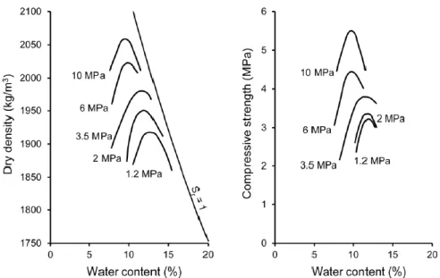
Figure 2.2 Compaction curves and variation of compressive strength with water content and compaction pressure (Olivier and Mesbah 1986)
Olivier and Mesbah (1986) studied the effect of the static compaction pressure on the mechanical properties of the “Isle d’Abeau” earth, using cylindrical samples at different pressure levels (from 1.2 MPa to 10 MPa). The optimum water content and the corresponding
21
maximum dry density for each compaction pressure is determined through testing at different water contents. After compaction, samples were stored at constant temperature (27 °C) and relative humidity (60%) and then tested under unconfined compression until failure. Results in Figure 2.2 confirmed that compressive strength increases as dry density increases.
Another study by Morel et al. (2007) also verifies this point. Compressive strength of compressed earth blocks, made of both stablilised earth and unstabilised earth, is strongly related to dry density achieved in compaction. Compressive strength of individual blocks consistently increases with increasing density, as shown in Figure 2.3.
Figure 2.3 Variation of compressive strength with dry density (Morel et al. 2007)
In another study by Kouakou and Morel (2009), a very argillaceous earth with 25% clay content was used to fabricate two types of adobe: traditional adobe blocks and pressed adobe blocks (PABs). Traditional adobe blocks were manufactured by pouring the clay-water mixture at high water content inside wooden moulds with dimensions of 310×150×73 mm3 and subsequently drying the demoulded blocks to the sun. Pressed adobe blocks were instead manufactured at much lower water contents and compressed to 2 MPa for increasing density. Both of these two kinds of adobe were cured in the laboratory at room temperature (22 °C) with a humidity of 60% until the block weight became constant. After curing, an unconfined compression test including three loading-unloading cycles at 30% of the compressive strength was carried out in order to determine their compressive strength, initial tangent modulus (Et) and equivalent modulus during cycles (Eeq).
Results (illustrated in Figure 2.4) indicate that the compressive strength of adobes and PABs increases with dry density. Adobe and PABs have an elastoplastic behavior with accumulated