HAL Id: hal-02480069
https://hal.archives-ouvertes.fr/hal-02480069
Submitted on 14 Feb 2020
HAL is a multi-disciplinary open access
archive for the deposit and dissemination of
sci-entific research documents, whether they are
pub-lished or not. The documents may come from
teaching and research institutions in France or
abroad, or from public or private research centers.
L’archive ouverte pluridisciplinaire HAL, est
destinée au dépôt et à la diffusion de documents
scientifiques de niveau recherche, publiés ou non,
émanant des établissements d’enseignement et de
recherche français ou étrangers, des laboratoires
publics ou privés.
Copyright
Mohammed Mokhtari, Smail Zouggar, Nacer-Kouider M’Sirdi, Mohamed
Elhafyani
To cite this version:
Mohammed Mokhtari, Smail Zouggar, Nacer-Kouider M’Sirdi, Mohamed Elhafyani. Contribution to
Power Maximization of an Asynchronous Wind Electric Water Pumping System Using Single Input
Fuzzy Logic Controller & Modified Enhanced Perturb and Observe. Conference on Smart Information
& Communication Technologies SMARTICT 19, Sep 2019, Saidia, Morocco. �hal-02480069�
Contribution to Power Maximization of an Asynchronous
Wind Electric Water Pumping System Using Single Input
Fuzzy Logic Controller & Modified Enhanced Perturb
and Observe
Mohammed MOKHTARI(1), Smail ZOUGGAR(1), Nacer K M’SIRDI (2), Mohamed Larbi ELHAFYANI (1)
1 University Mohammed 1st, School of Technology (L.E.E.M), 60000 Oujda, Morocco 2 LSIS, CNRS UMR 6168. Dom. Univ. St Jrme, Av. Escadrille Normandie - Niemen 13397.
Marseille. France
Abstract. This paper investigates the efficiency of an original approach for
Max-imum Power Point Tracking (MPPT) algorithm applied to a Wind Electric Water Pumping System (WEWPS). The studied model is developed under Matlab/Sim-ulink software and consists of an asynchronous wind turbine, a Static Var Com-pensator (SVC) and a centrifugal water pump driven by a three phase Induction Motor (IM). The proposed control technique seeks to improve water flow rate by exploring the maximum amount of electrical power produced by the asynchro-nous wind turbine in a wide range of wind speed. Theoretical analysis as well as simulation results have shown that the highest electrical power rate depends on the value of the produced voltage which can be controlled by the SVC using sin-gle input fuzzy logic regulator. Modified Enhanced Perturb and Observe (MEPO) algorithm is then used in this application to calculate the optimal value of the voltage reference that ensure maximum electric power extraction and hence max-imal water flow rate. Moreover, a comparison have been made with the conven-tional P&O algorithm to prove the superior performance of the proposed ap-proach which does neither require to measure wind speed nor to know the WEWPS parameters.
Keywords: Asynchronous Wind Turbine, Centrifugal Water Pump, MPPT,
MEPO, SIFLC, SVC.
1
Introduction
Wind energy sources are today an attractive alternative for electric power generation, it represent a competitive and promising renewable energy, especially, for energizing relatively small stand-alone systems in developing countries, where many people have no access to an AC power grid [15] [8][13].
In the literature, several system for water pumping application have been studied using different topology, configurations and control strategy, most of them uses SEIG or PMSG or BDFIG etc. as generator and either DC or AC motor to drive the pump [5][6][4][14].
In the different cases, an MPPT control algorithm can be employed in order to capture the maximum power from available wind. A variety of MPPT techniques have been employed for Wind Energy Conversion System (WECS) such as Incremental and Con-ductance method (INC), Perturb and Observe (P&O) method, Fuzzy Logic Controller (FLC) and many Evolutionary Algorithms [16][9].
In this paper, a modified enhanced MPPT algorithm is applied to the structure of the proposed wind electric water pumping system in order to maximize the water flow rate. This algorithm is simple, fast, efficient, and more importantly, does not require wind speed measurement.
The present work is organized as follows: Section 2 presents the mathematical model of the studied system. Section 3 presents the MPPT techniques. Section 4 presents the simulation and its results with a discussion and Section 5 concludes this paper.
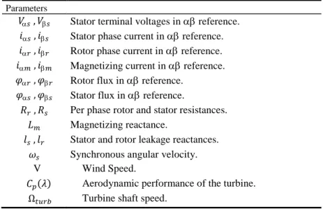
Table 1. Nomenclature.
Parameters
𝑉 , 𝑉 Stator terminal voltages in reference. 𝑖 , 𝑖 Stator phase current in reference. 𝑖 , 𝑖 Rotor phase current in reference. 𝑖 , 𝑖 Magnetizing current in reference. 𝜑 , 𝜑 Rotor flux in reference.
𝜑 , 𝜑 Stator flux in reference.
𝑅 , 𝑅 Per phase rotor and stator resistances.
Magnetizing reactance.
, Stator and rotor leakage reactances. 𝜔 Synchronous angular velocity. V Wind Speed.
𝐶𝑝 𝜆 Aerodynamic performance of the turbine.
Ω Turbine shaft speed.
2
System description and modeling
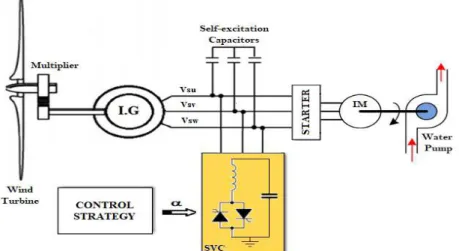
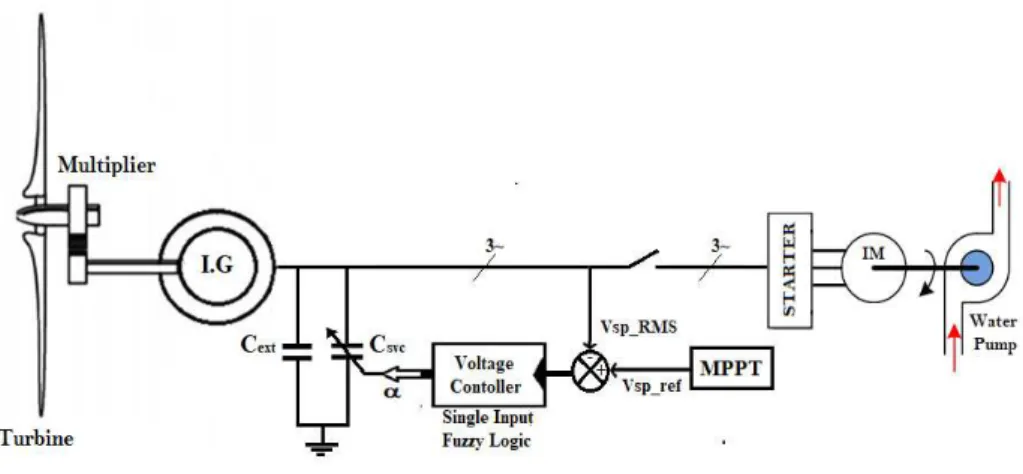
The complete system shown in Fig. 1 can be divided into three major parts. The first one is the renewable power generator source that capture and transform wind power to electric power, it consists of a three blade wind turbine, a multiplier and an Induction
Generator (IG) with its self-excitation capacitors. The second part consists of a Static Var Compensator (SVC) with its control strategy designed to maximize the electric power flow by controlling the produced voltage. Finally, the third part is the electric water pumping system with its starter that will be explored to transfer water from a suction point to the storage tank to be used for irrigation or other needs [10] [12].
Fig. 1. Schematic diagram of the studied system
2.1 Wind Turbine Model
Several models of wind turbines have been developed and can be found throughout the bibliography [7] [11]. Since the electrical behavior of the system is our main point of interest the following model is assumed:
Fig. 2. Schematic diagram of the turbine model.
2.2 Self-Excited Induction Generator Model
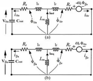
Because of its high efficiency and less maintenance, the self-excited induction genera-tor offers important advantages in construction and operation for standalone small wind turbines application [1]. The SEIG model developed in this work is represented in reference frame. Its equivalent circuit at a steady-state operation is shown in Fig. 3 with Lm been a function of the magnetizing current im [2].
Fig. 3. Equivalent circuit of the SEIG in reference frame
The electromagnetic torque produced by the induction generator is defined as:
𝐶 = 𝑝. 𝑚
𝑟 𝜑. 𝑖− 𝜑𝑖 (1)
2.3 Water pump Model
The chosen hydraulic system for this application is formed by a three phase induction motor to which a centrifugal pump is attached. Induction machines are widely used in water pumping activities because they are robust, inexpensive and easily replaceable in case of failure [3]. Hence, the IM is also modeled in reference frame:
𝑉𝑝= 𝑅𝑝. 𝑖𝑝+𝑑𝜑𝑑𝑝 𝑉𝑝= 𝑅 . 𝑖𝑝+𝑑𝜑𝑝 𝑑 𝑉𝑝= = 𝑅𝑝. 𝑖𝑝+𝑑𝜑𝑝 𝑑 − 𝜔 𝑝. 𝜑𝑝 𝑉𝑝= = 𝑅𝑝. 𝑖 𝑝+ 𝜑𝑟𝑝+ 𝜔𝑝. 𝜑𝑝 (2) 𝜑𝑝= 𝑝. 𝑖𝑝+ 𝑝. 𝑖 𝑝 𝜑𝑝= 𝑝. 𝑖 𝑝+ 𝑝. 𝑖 𝑝 𝜑𝑝= 𝑝. 𝑖 𝑝+ 𝑝. 𝑖 𝑝 𝜑𝑝= 𝑝. 𝑖𝑝+ 𝑝. 𝑖 𝑝 (3)
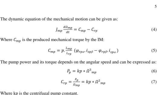
The dynamic equation of the mechanical motion can be given as:
𝑝 𝛺𝑚𝑝= 𝐶 𝑝− 𝐶𝑝 (4) Where 𝐶 𝑝 is the produced mechanical torque by the IM:
𝐶 𝑝= 𝑝. 𝑚𝑝𝑟𝑝 𝜑 𝑝. 𝑖 𝑝− 𝜑𝑝. 𝑖𝑝 (5) The pump power and its torque depends on the angular speed and can be expressed as: 𝑃𝑝= 𝑝 ∗ 𝛺 𝑝 (6) 𝐶𝑝=𝛺𝑃𝑚𝑝𝑝 = 𝑝 ∗ 𝛺 𝑝 (7) Where kp is the centrifugal pump constant.
The peak current of the electric water pump at transient phase when direct start is realized is higher than nominal current provided by the SEIG. Therefore a starter is used during starting phase to limit the starting current and avoid voltage collapse when the pump is connected to the asynchronous wind turbine.
2.4 Static Var Compensator Model
The Static Var Compensator FC-TCR type consists of a fixed capacitance C and an inductance L in series with a bi-directional thyristor valve that are fired symmetrically in an angle control range of 90° to 180°. At fundamental frequency, the total equivalent impedance of the SVC is shown in Fig. 4 and can be represented using the following expression [5]: 𝑋𝑉𝐶 𝛼 = 𝑋 𝜋 𝑥 ⁄ 𝑖 𝛼 − 𝛼+𝜋 −𝑟𝑥1 (8)
Where 𝒓𝒙= 𝑿𝒄⁄ the limits of the compensator given by the firing angle limits and 𝑿𝑳
fixed by design.
3
Proposed Control strategy
The control technique aims to optimize the generator voltage by means of SVC in order to maximize the water electric pump output power. Many strategies were inves-tigated to achieve the MPPT. Two control methods are presented in this paper: the P&O and MEPO [8].
3.1 Maximum power point tracking technique
To maximize the water flow rate, the rotational speed of the motor which drive the centrifugal pump must be maximized. That’s can be done by maximizing the power absorbed by the motor pump group.
The MPPT process in the proposed system is based on directly adjusting the total excitation capacitor according to the result of the comparison of successive motor pump group input-power measurements.
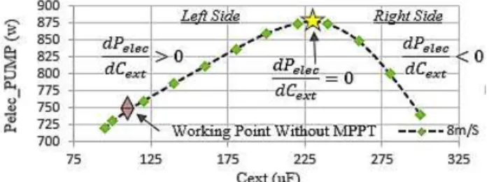
Fig. 5. Pelec_pump as function of Cext
Fig. 6. Vs_pump as function of Cext
From the characteristics Fig.5 and Fig.6, we can see that our system operate in the points on the left, so the objective is to led the system to work in the yellow star which correspond to the maximum absorbed power and maximum produced AC voltage Vsp. The required Maximum Power Point to Track is so function of the voltage Vsp, the excitation capacitor Cext and can be defined by the following objective function:
P _pu p 𝐶 𝑥 = P _pu p 𝑉 𝑝 𝑉 𝑝 𝐶 𝑥 = 0 (9)
Perturb & Observe Algorithm
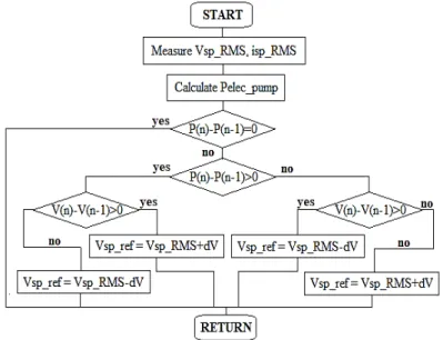
. It’s one of the simplest MPPT techniques as it involves measurement of the power
only. It is based on perturbing the voltage in small step and perceiving the resulting changes in power, as illustrated by Fig.6, [5]. This algorithm is based on the following procedure: if the operating voltage of the WEWPS is perturbed in a given direction and if the power supplied by the generator increases, it means that the operating point has moved toward the MPP, and therefore the voltage of the IG must still be settled in the same direction. Otherwise, if power operated generator decreases, the operating point is far from the MPP and therefore the direction of the disturbance in the voltage of operation must be reversed. Additionally, selecting an appropriate step size is not a simple task: though larger step-size means a faster response and more oscillations around the peak point, and hence, less efficiency, a smaller step-size improves effi-ciency but decreases the convergence speed.
Fig. 7. Flowchart P&O algorithm
MEPO: Modified Enhanced P&O Algorithm
. We propose, as a modified P&O Algorithm which will be more robust, the reference voltage given by:
𝑉𝑝_ = 𝑉𝑝_ + . ∆𝑃 _𝑝 𝑝. 𝑖𝑔𝑛 ∆𝑉𝑝 (10)
In case of no change in the output power after perturbation: ∆𝑃 _𝑝 𝑝= , then
𝑉𝑝_ = 𝑉𝑝_
In case of ∆𝑃 _𝑝 𝑝> , the power increase after positive perturbation of ∆𝑉𝑝 then let us continue in the same direction.
In case of ∆𝑃 _𝑝 𝑝< , the power decreases after positive perturbation of ∆𝑉𝑝 then let us continue in the reverse direction.
This method gives an enhanced variable step size algorithm. The step size is adjusted in proportionally to the power variation produced in the previous step. The step adjust-ment gain K is used for weighting this adjustadjust-ment step. It may be useful for oscillation avoidance and noise sensitivity.
Fig. 8. MEPO algorithm Simulink implementation
3.2 Voltage Control
To meet the referred voltage Vsp_ref, Static Var Compensator FC-TCR type is used to adjust the value of the total excitation capacitor (Cext + Csvc) of the WT. The control of the produced voltage is done via a single input fuzzy logic regulator as shown in Fig.8.
Fig. 9. Voltage control diagram
The per-phase thyristor firing angle is calculated by adding the new FLC output change in d to the old one. The operation of this technique is explained as shown in Fig.9.
Fig. 10. Voltage regulator
The proposed voltage controller is constructed by choosing the error between the ref-erence and the measured RMS value of the generated voltage as an input signal and the thyristor firing angle as an output signal. is defined by equation 11. It depends on a
constant value _𝑖𝑛 = . ° used initially to keep the value of Csvc equal to zero
until the lunch of the MPPT algorithm.
= _𝑖𝑛 + ∑ 𝑑 (11)
If Vs_RMS is equal to Vs_ref then error is equal to zero and d must also be equal to zero to keep equal to _int to avoid injecting or absorbing any reac-tive power.
If Vs_RMS is greater than Vs_ref (inductive mode) the error will be negative and d must be positive and its value should increase to absorb the excess of reactive power forcing the generated voltage to drop to the rated value. If Vs_RMS is less than Vs_ref (capacitive mode) the error will be positive and
d must be negative and its value should increase to inject the needed reactive
power to reach the rated voltage value.
The selected range for the input/output variables must be well chosen. Usually, it’s desirable to select the standard range of (+/-1). Yet, since the power system was well studied, the range for a variable is already known, and so the normalization step for the input was abandoned.
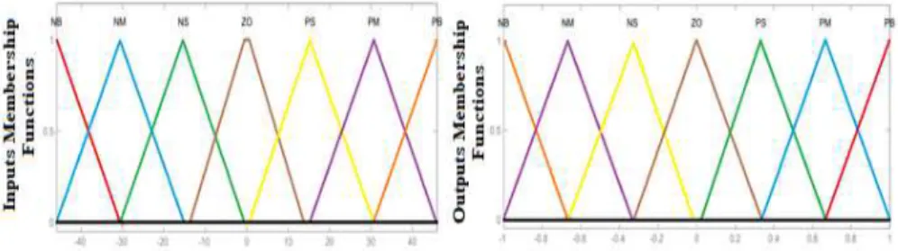
Fig. 11. Input and output membership functions of the SFLC
The seven linguistic variables used are Negative Big (NB), Negative Medium (NM), Negative Small (NS), Zero (ZO), Positive Small (PS), Positive Medium (PM) and Positive Big (PB). The 7 rules have been built as represented in Fig.9.
Fig. 12. The chosen rules of the SIFLC
4
Simulation results & analysis
To evaluate the MPPT performance, the designed control system is simulated using MATLAB/Simulink software package and the obtained results will be discussed in this section.
The wind speed variation profile is considered as depicted in Fig. 13. It can be de-vised to fourth zone. The first one is between 0s and 3.3s representing the average wind speed that ensure the excitation of the IG. Zone 1 and 3 are the same and help to observe the behavior of the system when the wind speed rises above the rated wind speed (8 m/s). Zone 2 in the other side is to test the aero-generator at low wind speed value.
Fig. 13. Wind speed profile
At second 3.3 the MPPT control is lunched synchronously with the wind speed var-iation. From Fig.14 we can observe that the absorbed power by the electric water group have been increased using both MPPT algorithm. However, the MEPO is showing bet-ter results especially when the wind speed get under the rated value. At the 7th second without MPPT control the Pelec_pump was at 590W. Once the MEPO is applied the power rises up to 630W unlike the P&O algorithm which have improved the power to only reach 600W.
Fig. 14. Variation of the absorbed power by the motor pump with and without MPPT
control-lers
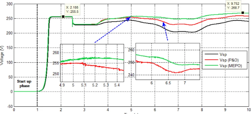
The observed operating voltage of the wind electric water pumping system in Fig.15 when P&O algorithm is used is lower than the one generated with MEPO algorithm, this is due to the inability of the MPPT algorithm to generate quickly the optimal value with a fixed step, which represent another drawback for the P&O method.
Fig. 15.Variation of the produced voltage Vs during power maximization
5
Conclusion
This work has allowed us to complete our research on an autonomous wind electric water pumping system. The modeling of the studied system have been first presented, then a comparative analysis between P&O and MEPO algorithms has been discussed to support the proposed approach for power maximization that gives more efficient and reliable results at variable wind speed condition.
References
1. Mokhtari, M., Zouggar, S., Elhafyani, M. L., Ouchbel, T., Benzaouia, S., & Fannakh, M. (2018, April). Design, Simulation and Performance Analysis of Voltage Regulator Based on STATCOM for Asynchronous Wind Turbine. In International Conference on Electronic Engineering and Re-newable Energy(pp. 498-509). Springer, Singapore.
2. Mokhtari, M., Zouggar, S., Elhafyani, M. L., Ouchbel, T., M’sirdi, N. K., & Naaman, A. (2018, December). Voltage Stability Improvement of an Asynchronous Wind Turbine using Static Var Compensator with Single Input Fuzzy Logic Controller. In 2018 6th International Renewable and Sustainable Energy Conference (IRSEC) (pp. 1-6). IEEE.
3. Elhafyani, M. L., Zouggar, S., Benkaddour, M., & Zidani, Y. (2006). Permanent and dynamic behaviours of self-excited induction generator in balanced mode. Moroccan Journal of Condensed Matter, 7.
4. Daili, Y., Gaubert, J. P., & Rahmani, L. (2015). Implementation of a new maximum power point tracking control strategy for small wind energy conversion systems without mechanical sen-sors. Energy Conversion and Management, 97, 298-306.
5. Ouchbel, T., Zouggar, S., Elhafyani, M. L., Seddik, M., Oukili, M., Aziz, A., & Kadda, F. Z. (2014). Power maximization of an asynchronous wind turbine with a variable speed feeding a centrifugal pump. Energy Conversion and Management, 78, 976-984.
6. Zeddini, M. A., Pusca, R., Sakly, A., & Mimouni, M. F. (2016). PSO-based MPPT control of wind-driven Self-Excited Induction Generator for pumping system. Renewable Energy, 95, 162 177.
7. Lara, D., Merino, G., & Salazar, L. (2015). Power converter with maximum power point tracking MPPT for small wind-electric pumping systems. Energy Conversion and Management, 97, 53-62.
8. Abdullah, Majid A., et al. "A review of maximum power point tracking algorithms for wind en-ergy systems." Renewable and sustainable enen-ergy reviews 16.5 (2012): 3220-3227.
9. Aubrée, R., Auger, F., Macé, M., & Loron, L. (2016). Design of an efficient small wind-energy conversion system with an adaptive sensorless MPPT strategy. Renewable Energy, 86, 280-291. 10. Atawi, Ibrahem E., and Ahmed M. Kassem. "Optimal Control Based on Maximum Power Point Tracking (MPPT) of an Autonomous Hybrid Photovoltaic/Storage System in Micro Grid Appli-cations." Energies 10.5 (2017): 643.
11. Lahfaoui, B., Zouggar, S., Mohammed, B., & Elhafyani, M. L. (2017). Real Time Study of P&O MPPT Control for Small Wind PMSG Turbine Systems Using Arduino Microcontroller. Energy Procedia, 111, 1000-1009.
12. Fathabadi, Hassan. "Novel high efficient speed sensorless controller for maximum power extrac-tion from wind energy conversion systems." Energy Conversion and Management 123 (2016): 392-401.
13. Tiwari, Ramji, and N. Ramesh Babu. "Fuzzy logic based MPPT for permanent magnet synchro-nous generator in wind energy conversion system." IFAC-PapersOnLine 49.1 (2016): 462-467. 14. Sefidgar, Hadi, and S. Asghar Gholamian. "Fuzzy logic control of wind turbine system connection
to PM synchronous generator for maximum power point tracking." International Journal of Intel-ligent Systems and Applications 6.7 (2014): 29.
15. Farhat, Maissa, Oscar Barambones, and Lassaâd Sbita. "Efficiency optimization of a DSP-based standalone PV system using a stable single input fuzzy logic controller." Renewable and Sustain-able Energy Reviews 49 (2015): 907-920.
16. Eltamaly, Ali M., and Hassan M. Farh. "Maximum power extraction from wind energy system based on fuzzy logic control." Electric Power Systems Research 97 (2013): 144-150.