Publisher’s version / Version de l'éditeur:
Proceedings of the 2nd European Conference on Microfluidics, 2010-12-08
READ THESE TERMS AND CONDITIONS CAREFULLY BEFORE USING THIS WEBSITE.
https://nrc-publications.canada.ca/eng/copyright
Vous avez des questions? Nous pouvons vous aider. Pour communiquer directement avec un auteur, consultez la
première page de la revue dans laquelle son article a été publié afin de trouver ses coordonnées. Si vous n’arrivez pas à les repérer, communiquez avec nous à PublicationsArchive-ArchivesPublications@nrc-cnrc.gc.ca.
Questions? Contact the NRC Publications Archive team at
PublicationsArchive-ArchivesPublications@nrc-cnrc.gc.ca. If you wish to email the authors directly, please see the first page of the publication for their contact information.
NRC Publications Archive
Archives des publications du CNRC
This publication could be one of several versions: author’s original, accepted manuscript or the publisher’s version. / La version de cette publication peut être l’une des suivantes : la version prépublication de l’auteur, la version acceptée du manuscrit ou la version de l’éditeur.
Access and use of this website and the material on it are subject to the Terms and Conditions set forth at
Fabrication of themal plastic micorfluidic devices with peristalic
micropumps and microvalves
Li, K.; Miville-Godin, C.; Normandin, F.; Roy, E.; Veres, T.
https://publications-cnrc.canada.ca/fra/droits
L’accès à ce site Web et l’utilisation de son contenu sont assujettis aux conditions présentées dans le site LISEZ CES CONDITIONS ATTENTIVEMENT AVANT D’UTILISER CE SITE WEB.
NRC Publications Record / Notice d'Archives des publications de CNRC: https://nrc-publications.canada.ca/eng/view/object/?id=b85abb7a-afa6-4c62-b81a-a3b783385127 https://publications-cnrc.canada.ca/fra/voir/objet/?id=b85abb7a-afa6-4c62-b81a-a3b783385127
Proceedings of the 2 European Conference on Microfluidics - Microfluidics 2010 - Toulouse, December 8-10, 2010
DRAFT µFLU10-200
FABRICATION OF THERMAL PLASTIC MICROFLUIDIC DEVICES
WITH PERISTALTIC MICROPUMPS AND MICROVALVES
K. Li, C. Miville-Godin, F. Normandin, E. Roy, T. Veres
Industrial Materials Institute, National Research Council, Canada, 75, Boul. De Mortagne, Boucherville, Québec, Canada, J4B 6Y4
KEY WORDS
Microfluidics, Micropumps and Microvalves, Thermoplastic Elastomer
ABSTRACT
Microfluidic devices with peristaltic pumps and valves have been fabricated based on the thermal plastic materials by using the rapid hot-embossing method. Two types of configurations of the microfluidic devices are presented. Both of them are based on the use of membrane layer made of thermoplastic elastomer materials. The frequency and pressure dependence of the pumping rate are studied and compared among the conventional, S-shape and U-shape designs. The maximum flow rate of the conventional peristaltic design is about 2 times of that of the U-shape design with the identical microfluidic channel under the same operation pressure. The advantage of S-shape and U-shape peristaltic design over the conventional design is that the number of electromagnetic valves used in the pneumatic manifold can be reduced. A simple rotary microfluidic device with peristaltic pumps was fabricated and the microvalving, micropumping and micromixing operations have been demonstrated.
1. INTRODUCTION
Medical diagnostics is an area of great interest that has recently fuelled an increased interest for the development of disposable rapid diagnostics devices for point-of-care applications. Most of the microfluidic devices are fabricated using either “hard lithography” in glass or “soft lithography” in polymers such as PDMS [1]. Transition to large scale use of lab-on-chip systems (LOC) requires of fabrication technologies and materials amendable for rapid and low-cost fabrication, simple procedures for bonding as well as stable surface treatments for bio-molecules capture and immobilization.
Thermoplastic elastomer (TPE) has been recently demonstrated to be biocompatible and surface stable materials that allow to rapidly fabricate complex microfluidic devices at relatively low cost because of its remarkable advantages in the soft fabrication and microfluidic behaviors.[2-5]. Herein we report on the fabrication by hot-embossing of the TPE based microfluidic devices with peristaltic pumps and valves. Two types (A and B) of structures are presented. Type A is a three layer structure with the first layer containing the microfluidic channel embossed on a thermoplastic COC Zeonor 1060R. The second layer containing the membrane and the microfluidic control layer is made of TPE. The third layer is made of Zeonor 1060R which contains the inlets and outlets and is used a capping layer for the whole structure. Type B consists of the microfluidic channel layer and the micropumps and valves layers, both of them were made of TPEs, then bonded on a thermoplatics Zeonor 1060R substrate. A custom made manifold was used for injecting the air in a pneumatic control layer. The pumping performance of different designs of the pneumatic micropumps (for example a conventional peristaltic pneumatic micropump design and serpentine shape design (S-shape or U shape design) under different actuated air pressures and the operational frequencies were studied and compared. The implementation of a micromixer based on the use of the peristaltic pumps has been demonstrated.
Proceedings of the 2 European Conference on Microfluidics - Microfluidics 2010 - Toulouse, December 8-10, 2010
2. EXPERIMENTS AND RESULTS
2.1 Fabrication Process
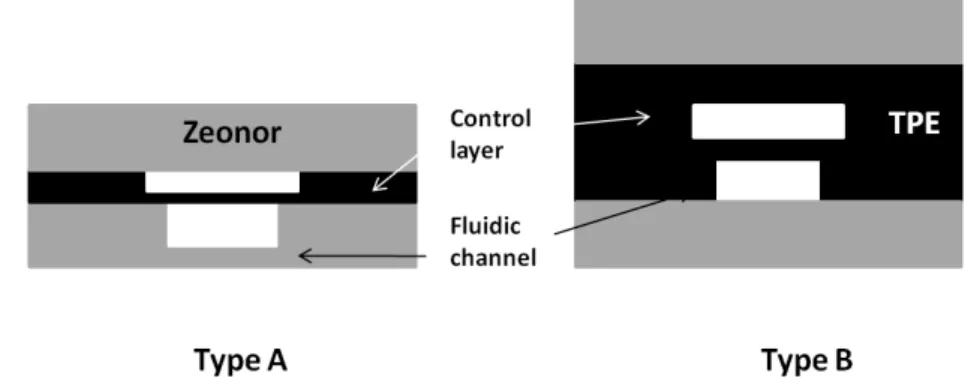
Figure 1 shows the schematic structure of the peristaltic micropumps and microvalves. Type A consists of a fluidic channel layer and a layer for pneumatic control. The microfluidic channel was hot-embossed on a thermoplatstic substrate Zeonor 1060R by using an epoxy mould while the pneumatic control layer is made of TPE materials by hot-embossed by using a SU8 mould on Si substrate. By controlling the initial thickness of the starting TPE materials and the thickness of the SU8 layer in the mould as well as the hot-embossing process, one can control the residual thickness of the embossed TPE layer in the control channel which is also used as the membrane layer. The thickness of this membrane layer is typically around 100 um. The type B structure demonstrated herein consists of two Zeonor layers and two TPE layers. The Zeonor layers are used as the supporting substrate and cap layer. One of the TPE layers is used as the microfluidic channel layer and the another TPE layer is used as the pneumatic control layer. By controlling the total thickness of the fluidic layer and the depth of the channel, we are able to adjust the membrane layer to be in thickness of 100um.. In configuration of Type A, the microfluidic channel is fabricated on the hard thermal plastic layer which also served as the supporting layer.The microfluidic channel is more robust in type A than that in type B during the bonding process, but it requires a special mould in the hot-embossing process in order to fabricate the microfluidic channel on hard thermoplastic material..
Fig.1 schematic drawing of two configurations of the peristaltic pumping design (type A and type B).
The basic fabrication process is similar for the two types of the fluidic structures. Two SU-8 moulds were fabricated by standard photolithography method. The first one is used for the embossing of microfluidic channel layer and the second one is for the pneumatic control layer. For example, in order to make a SU8 mould for the pneumatic control layer, a layer of SU-8 GM1070 photoresist with thickness of about 100 µm was spin-coated on a 4’’ silicon wafer, followed by pre-bake for 30 min at 65 o
C and 2 hours at 95 oC. It was exposed by UV i-line Hg light using an EVG 6200 mask aligner through a high-definition transparent mask, followed by post baking for 30 min at 65oC and 1 hours at 95oC. The resist development was then performed in propylene glycol monomethyl ether acetate and the wafer was rinsed with isopropanol and dried with a stream of nitrogen gas. It was then hard-baked at 160 °C for 2 hours. The SU-8 mould was finally treated with trichloro(1H,1H,2H,2H-perfluorooctyl)silane using vapor phase deposition to obtain an anti-adhesive layer and to facilitate the release of thermoformed TPE form the mould. In order to make the microfluidic channel on Zeonor substrate, an epoxy mould or a polymer mould was fabricated by transferring the micro-pattern from the SU8 mould.
Both fluidic channel and pneumatic control channel were
fabricated by using the hot-embossing method. The h
ot embossing was carried out on an EVG 520
HE tool, the maximum operating temperature and embossing force of the instrument are 200
oC,
and 40 kN, respectively. Heating and cooling modules were active on both upper and lower plates
at a rate of 20 and 10
oC / min, respectively, the base pressure of the chamber is about in 0.1 mbar.
Typical embossing conditions are: 2 min at 135
oC with force of 5kN for making pneumatic control
layer on TPE with starting thickness of 0.3 to 0.4 mm and 5 min at 140
oC with force of 6kN for
making the microfluidic channel on Zeonor substrate with thickness of 1mm. The thickness of the
Zeonor cap layer is in about1mm. Holes with diameter of 1mm used for connecting the inlets and
outlets as well as the pneumatic control layer were punched by a puncher. The fluidic channel and
the pneumatic control layer as well as the capping layer are aligned together under microscopy and
bonded by putting it inside an oven for 5 min at 90
oC. Teflon tube with inner diameter of 0.3um
Proceedings of the 2 European Conference on Microfluidics - Microfluidics 2010 - Toulouse, December 8-10, 2010
layer and connected to the pneumatic control manifold by silicone tubing with ID of 0.64mm and
OD of 1.2mm during the flow testing. DI water with fluorescence beads with diameter of 3um and
30um is used as fluidic liquid and the flow behavior was studied under the fluorescence
microscopy.
2.2 Microfluidic Device with Peristaltic Pumps and Valves
To prove the functionality of the microfluidic devices with peristaltic micropump and microvalves made of TPE materials, we made a very simple design as shown in Fig.2 (a). The main channel is designed in a square loop. Once the liquid is pumped into the square loop, closed two valves (V1 and V2), the peristaltic pump P is activated by the sequence of open/close of the three electromagnetic valves (EMV). The flow direction is dependent on the order to open/close these three EMV. Fig.2(b) shows a image of the device after assembly. The red Teflon tubes are used for the connection to the pneumatic control manifold and the blue Teflon tubes are used for the inlet and outlet of the liquid. The depth of the fluidic channel is 50um and the width of the channel in the square loop is 1mm while the width of the channel in the valve area is 0.4mm. The length of the square loop is 13mm. Fig.2 (c) shows the optical microscopy image of the finger type valve and conventional peristaltic pump. The width of the control channel is 1mm and the gap between two control channel is 0.5mm and the depth of the pneumatic control channel is 100um.
Fig.2 Microfluidic device with peristaltic pumping and valves based on TPE materials. (a) Autocad design , (b) after assembly (configuration of Type A) and connection of inlets/outlets; (c) optic microscopy images of pumping and
valves.
To study the flow behavior, fluorescence beads with diameter of 3um were added into the DI water. We use the fluorescence microscopy to monitor the trajectory of the fluorescence bead. Flow rate is estimated based on the distance traveled by the bead within fixed observation time. Fig. 3 shows the frequency and pressure dependence of the flow rate. Basically the flow rate increases with increasing the pressure up to a threshold of (13psi) at which the deflection of the TPE membrane layer reached maximum. The flow rate keeps at constant when the pressure is above 13psi because the deflection of the TPE membrane layer does not change any more. In this experiment, the pumping frequency is fixed at about 5 Hz. Here the frequency is defined as the number of cycles of the pumping operation per second. And one cycle of the pumping operation consists of the following three steps, 1) open P1 close P2, 2) open P2, close P3 and 3) open P3 close P1. The time spent for completing the cycle includes the intrinsic time needed for the open/close cycle of the EMV valves (the intrinsic frequency of the close/open EMV valve is about 200 Hz) and all the waiting time between two processing steps (e.g., from step 1 to step 2). Fig. 3 (b) shows the frequency dependence of the flow rate. As expected, the flow rate increases with the frequency up to 6 Hz , beyond which the flow rate remains constant. The flow rate is limited by the intrinsic response time of the deflection of the TPE materials to the pressure. The deflected TPE will relax back to the original state when the pressure is released. The response frequency of the TPE to the pressure is behind the frequency of the pumping operation when it is above 6 Hz. In other words, the relaxation frequency of the TPE materials is not able to follow the frequency of the pumping operation when the pumping is operated above 6Hz. We
Proceedings of the 2 European Conference on Microfluidics - Microfluidics 2010 - Toulouse, December 8-10, 2010
have fabricated another two devices with the same design but in different channel width, 0.5mm, and 2mm. It is found that the flow rate is increased with increasing the width of the channel. As expected, the flow rate is also increased with increasing the depth of the channel provided that the deflection of the TPE membrane is large enough.
Fig.3 Pressure dependence of the pumping rate (left figure) and the frequency dependence of the pumping rate (right figure) for a microfluidic device with a conventional design of a peristaltic pump which are shown in Fig. 2.
Fig.4 optical microscopy images of U-shape peristaltic pump (a) and 5 turns S-shape peristaltic pump (b) as well as the frequency dependence of the pumping rate of a U-shape peristaltic pump with the same microfluidic design shown in
Fig. 2 in which the conventional peristaltic pump was replaced by a U-shape peristaltic pump.
Wang et al.[6] and Huang et al.[7] have demonstrated that a micropump system can be implemented based on serpentine-shape (S-shape) channel or U-shape channel in which only one EMV valve is required while three EMV valves are required in the design of the conventional peristaltic micropump. We have fabricated the microfluidic devices which are based on the same design shown in Fig.2 (a) but using S-shape and U-shape peristaltic pumps to replace the conventional pump. In order to demonstrate the back and forth flow in the design of S-shape pump or U-shape pump, two pumps sit oppositely in the square loop. In the conventional peristaltic pump design, we need only one set of pump to perform the operation of back and forth flow by changing the sequence of the close and open of the three EMV valves. But in both S-shape and U-shape peristaltic designs, we still need two EMV valves in order to perfume the back and forth flow operation. Fig. 4 (a) and (b) show the optical microscopy images of the fabricated TPE based peristaltic pumping in U-shape and S-shape, respectively. Fig. 4(c) shows the frequency dependence of the flow rate in U-shape peristaltic with the same design of the microfluidic channel shown in Fig.2(a). It was operated at 15psi. It is different from that of the conventional peristaltic design shown in Fig.3. The peak appears around 8 Hz. The maximum flow rate is about half of that in the conventional peristaltic design when they are operated at the same pressure. In the U-shape and S-shape design, the pumping rate is affected not only by the magnitude of deflection of the individual membranes, but also by the time interval between the deflections of adjacent membranes, which is a function of geometry of the control channel, namely the length and size of the of the small channel shown in Fig.4 (a) as well as the distance between two control channel in the S-shape and U-shape micro-channel.
Proceedings of the 2 European Conference on Microfluidics - Microfluidics 2010 - Toulouse, December 8-10, 2010
3. APPLICATION OF TPE PERISTALTIC MICOPUMPS AND VALVES
The microfluidic devices with integration of microvalves, micropumps and micromixers have been widely used to manufacture nanoparticles [8-10] because the microfluidic technologies offers a variety of advantages over traditional technologies in the synthesis of nanoparticles. The advantages include but not limit to a shorter reaction time, less sample consumption and a uniform particle size. Micromixer is one of the essential components of the microfluidic device in the synthesis of the nanoparticles. There are two types of micromixer: passive micromixer and active micromixer. Passive micromixers do not require external energy, and the mixing process depends only on diffusion or chaotic advection, like Y/T-shaped flow micromixer.[11] Active micromixers use energy input from the exterior for the mixing process. The external energy sources include electrokinetics, acoustics, magnetohydrodynamics and others. Herein, we will demonstrate that the integration of the peristaltic microvalves and micropumps can be one of the external energy source to generate the micromixing flow in the thermoplastic microfluidic device.
Fig.5 (a) Schematic drawing of the design of a peristaltic PCR mixer. (b) optical microscopy images of the device after assembly. (c) initial state of two colors liquid loaded in the chambers. (d) after peristaltic pumping for 30 seconds.
Fig.5(a) shows the schematic drawing of one of such microfluidic designs that is being used for mixing.. The blue part represents the fluidic layer. There are three chambers C1, C2 and C3 which are connected by three small channels. Two sets of inlets and outlets which are used for loading liquids. The red layer is the pneumatically controlling layer. V1, V2 and V3 are connected to three pneumatic EMV valves through silicon tubing. In this design two different types of liquid can be loaded. P1, P2 and P3 are connected to another three EMV valves through silicon tubing again, which are used for the activation of the peristaltic pumping. The device was fabricated based on the structure of type B shown in Fig.1. The channel depth of the fluidic layer is 100um and the channel depth of the pneumatic control layer is 200um. Zeonor 1060R was used as both the supporting and capping layers. Fig.5(b) shows a image of the device after assembly and connection of the Teflon tubing. After loading the liquid into the chambers and closing the valves V1, V2 or simply closing the inlets (I1, I2) and outlets (O1, O2), the liquid can be pumped from one chamber to another chamber by the operation of the pumping P1, P2 and P3 in sequence. For example, by simultaneously opening the EMV valves which are connected to P2 and P3, the liquid will be pushed to the chamber C1. The liquid will go to C2 if the EMV valves connecting to P3 and P1 are open simultaneously. The liquid will go to C3 if the EMV valves connecting to P1 and P2 are open. By repeating these three operations, the liquid will flow continuously from C1 to C2 to C3 and back to C1. The operation pressure can be as small as 5psi, it depends also on the time duration of the opening of the EMV valve. The typical cycle time tested in our experiment is 300ms. It works quite well even at 30ms. Fig.5(c) shows the status of the liquid inside the chambers after loading two different liquids (red in C2, and green in C1 and C3). Fig. 5(d) shows the status
Proceedings of the 2 European Conference on Microfluidics - Microfluidics 2010 - Toulouse, December 8-10, 2010
of the chambers after pumping for 30 seconds (about 100 cycles). The liquid becomes the same color in three chambers. It demonstrates that the current device design posses microvalving, micropumping and micromixing operations.
4. CONCLUSIONS
In summary, a fully thermoplastic based microfluidic device with peristaltic microvalves and micropumps has been successfully fabricated by using a rapid hot-embossing method. The membrane layer which was used in the device is made from thermoplastic elastomer. The performance of the TPE based membrane layer is comparable with PDMS materials which are widely used as the membrane layer in peristaltic micropumping device. The pumping performance was studied based on the conventional peristaltic design and was compared with the S-shaped and U-shaped peristaltic micropump designs. The maximum pumping rate is usually higher in the conventional design than that in the S-shaped and U-shaped design although it requires more pneumatic controlling valves in conventional design than the serpentine shape designs. One of the applications of this fully thermal plastic based microfluidic device with peristaltic microvalves and micropumps can be used as an active micromixer. The same microfluidic structure could be employed for the implementation of a polymerase chain reaction protocol too.
ACKNOWLEDGEMENTS
This work was supported by the National Research Council’s Genomics and Health Initiative Program. We would like to thank Hélène Roberge for her help in fabrication of the Zeonor 1060R substrate.
REFERENCES
[1] Xia, Y.N. and Whitesides, G. M. (1998). Soft lithography. Ann. Rev. Mater. Sci.28, 153-184. [2] E.Roy, M. Geissler, J. C. Galas, G. A. Diaz-Quijada and T.Veres, Submitted.
[3] Geissler, M., Roy, E., Diaz-Quijada, G. A., Galas, J. C., and Veres, T. (2009). Microfluidic patterning of minaturized DNA arrays on plastic substrates. ACS Applied Materials & Interfaces 1(7), 1387-1395. [4] Guillemette MD, Cui B, Roy E et al. (2009) Surface topography induces 3D self-orientation of cells and extracellular matrix resulting in improved tissue function Integrative Biology 1: 196-204.
[5] Li, K., Brassard, D., Normandin, F., Miville-Godin, C., Geissler, M., Roy, E., and Veres, T. (2009). Fabrication of Microfluidic Devices in Thermoplastic Elastomeric Materials for DNA Detection on Thermal Plastic Substrate. Symposium DD Proceedings, DD5.24, MRS Fall Meeting, Nov.30-Dec.4, 09, Boston,USA.
[6] Wang, C. H. and Lee, G. B. (2006). Pneumatically driven peristaltic micropums utilizing serpentine- shape channels. J. Micromech. Microeng. 16, 341-348.
[7] Huang, S. B., W, M. H. et al., (2008). A membrane-based serpentine-shape pneumatic micropump with pumping performance modulated by fluidic resistance. J. Micromech. Microeng. 18, 045008.
[8] Song, Y., Kumar, C.S., Hormes, J. (2004) Synthesis of plladiom nanoparticles using a continuous flow polymer micro reactor. J Nanosci Nanotechnol 4: 788-793.
[9]Hung, L.H., Lee, A.P. (2007). Microfluidic devices for the synthesis of nanoparticles and biomaterials. J Med Biol Eng 27:1-6.
[10] Yang ,SY, Cheng, F.Y., Yeh, C.S., Lee, G.B. (2010) Size-controlled synthesis of gold nanoparticles using a micro-mixing system. Microfluid Nanofluid 8:303-311.
[11] Legendre, LA., Bienvenue, JM., Roper MG., Ferrance, J. P., Landers, J. P. (2006) A simple, valveless microfluidic sample preparation device for extraction and amplification of DNA from nanoliter-volume samples. Anal Chem 78:1444-1451.