Publisher’s version / Version de l'éditeur:
International Journal of Geomechanics, 8, 1, pp. 2-10, 2009-01-01
READ THESE TERMS AND CONDITIONS CAREFULLY BEFORE USING THIS WEBSITE.
https://nrc-publications.canada.ca/eng/copyright
Vous avez des questions? Nous pouvons vous aider. Pour communiquer directement avec un auteur, consultez la première page de la revue dans laquelle son article a été publié afin de trouver ses coordonnées. Si vous n’arrivez pas à les repérer, communiquez avec nous à [email protected].
Questions? Contact the NRC Publications Archive team at
[email protected]. If you wish to email the authors directly, please see the first page of the publication for their contact information.
NRC Publications Archive
Archives des publications du CNRC
This publication could be one of several versions: author’s original, accepted manuscript or the publisher’s version. / La version de cette publication peut être l’une des suivantes : la version prépublication de l’auteur, la version acceptée du manuscrit ou la version de l’éditeur.
For the publisher’s version, please access the DOI link below./ Pour consulter la version de l’éditeur, utilisez le lien DOI ci-dessous.
https://doi.org/10.1061/(ASCE)1532-3641(2008)8:1(2)
Access and use of this website and the material on it are subject to the Terms and Conditions set forth at
Intelligent cable shovel excavation modeling and simulation
Frimpong, S.; Hu, Y.
https://publications-cnrc.canada.ca/fra/droits
L’accès à ce site Web et l’utilisation de son contenu sont assujettis aux conditions présentées dans le site LISEZ CES CONDITIONS ATTENTIVEMENT AVANT D’UTILISER CE SITE WEB.
NRC Publications Record / Notice d'Archives des publications de CNRC:
https://nrc-publications.canada.ca/eng/view/object/?id=a023c5c6-944a-4907-b01b-e4cfe983624f https://publications-cnrc.canada.ca/fra/voir/objet/?id=a023c5c6-944a-4907-b01b-e4cfe983624fhttp://irc.nrc-cnrc.gc.ca
I n t e l l i g e n t c a b l e s h o v e d e x c a v a t i o n m o d e l i n g
a n d s i m u l a t i o n
N R C C - 5 1 1 2 4
F r i m p o n g , S . ; H u , Y .
2 0 0 8 - 0 1 - 0 1
A version of this document is published in / Une version de ce document se trouve dans: International Journal of Geomechanics, v. 8, no. 1, pp. 1-10,
DOI: http://dx.doi.org/10.1061/(ASCE)1532-3641(2008)8:1(2)
The material in this document is covered by the provisions of the Copyright Act, by Canadian laws, policies, regulations and international agreements. Such provisions serve to identify the information source and, in specific instances, to prohibit reproduction of materials without written permission. For more information visit http://laws.justice.gc.ca/en/showtdm/cs/C-42
Les renseignements dans ce document sont protégés par la Loi sur le droit d'auteur, par les lois, les politiques et les règlements du Canada et des accords internationaux. Ces dispositions permettent d'identifier la source de l'information et, dans certains cas, d'interdire la copie de documents sans permission écrite. Pour obtenir de plus amples renseignements : http://lois.justice.gc.ca/fr/showtdm/cs/C-42
Intelligent Cable Shovel Excavation Modeling and Simulation
Samuel Frimpong
1and Yafei Hu
2Abstract: Cable shovel excavators are used for primary production of geomaterials in many surface mining operations. A major problem
in excavation is the variability of material diggability, resulting in varying mechanical energy input and stress loading of shovel dipper-and-tooth assembly across the working bench. This variability impacts the shovel dipper and tooth assembly in hard formations. In addition, the geometrical constraints within the working environment impose production limitations resulting in low production efficiency and high operating costs. An intelligent shovel excavation 共ISE兲 technology has been proposed as a potential solution to these problems. This paper addresses the requirements of the dynamic models of the cable shovel underlying the ISE technology. The dynamic equations are developed using the Newton–Euler techniques. These models are validated with real-world data and simulated in a virtual prototype environment. The results provide the path trajectories, dynamic velocity and acceleration profiles, and dimensioned parameters for optimum feed force, torques and momentum of shovel boom-dipper assembly for efficient excavation. The optimum digging forces and resistances for the cable shovel excavators are modeled and used to predict optimum excavation performance.
DOI: 10.1061/共ASCE兲1532-3641共2008兲8:1共2兲
CE Database subject headings: Excavation; Mining; Simulation; Artificial intelligence.
Introduction
Shovel excavators are widely used as primary production equip-ment in surface mining operations for removing overburden and ore materials. The shovel–truck mining method in surface mining is flexible, efficient, and it can be easily relocated to different operating environments. The efficiency and costs of mining op-erations greatly depend on the efficient use of these capital-intensive shovel excavators. However, the shovel–truck mining method can be rendered inefficient from operating, environmen-tal, topography, and operator constraints. Any naturally occurring formation is characterized by the defining properties of the con-stituent soils and rocks. These properties are shaped by the pre-and postformation chemical pre-and mechanical processes to yield the relative ease of digging or excavating the formation. Thus, an excavator’s cutting force is a function of the formation properties, machine–formation interactions and the operating parameters of an excavator. The formation parameters include cohesion, internal friction angle, density, water saturation, formation hardness and compaction, abrasiveness, the angle of formation failure wedge, and shear plane angle. The machine–formation interaction param-eters include adhesion and external friction angle. The operating parameters also include blade travel velocity, cutting angle, tool working depth beneath surface, and surcharge pressure acting ver-tically on formation surface. These defining characteristics must
be controlled through optimization to yield efficient excavation. Careful planning and execution of shovel operations, reloca-tions, and interactions with other production equipment are there-fore vital to efficient operating performance. In addition, the physical and mechanical properties of materials being excavated have severe impact on the efficiency of a shovel excavator. They usually result in varying mechanical energy input and stress load-ing of shovel dipper-and-tooth assembly across the workload-ing bench when the shovel dipper is in contact with mining surfaces during excavation. Stress development and fatigue failure in equipment components such as booms cause unplanned down-times, reduced efficiency, and high production costs. Complex and unstructured mining environments have a huge impact on shovel dipper and tooth assembly. Often, space limitations may limit the shovel–truck mining process to a single backup method, which is highly inefficient and unproductive 共Frimpong et al. 2003兲.
A potential solution to the problems described above is the application of an intelligent shovel excavation 共ISE兲 system that is responsive to shovel–formation interactive forces with space geometry scanning capability during excavation as illustrated in Fig. 1 共Frimpong et al. 2001兲. Fig. 1 consists of a shovel excava-tor, vision systems, sensors, and receivers that work together to capture mechanical energy, stress, and resistance information from a mining face, with space geometry scanning capability, in real time. These data are transmitted, processed, and displayed on an on-board screen in the operator’s cabin. An operator can there-fore assess local variation in the bench environment based on the information displayed on the screen and make real-time decisions. These decisions may lead to fragmentation of extremely hard for-mations, in-pit blending and stockpiling of materials as per the plant requirements. This vision system may also be used to plan the three-dimensional 共3D兲 space geometry requirements of the shovel–truck mining method. The results may also be used to develop virtual prototype simulators for training operators within safety and cost constraints 共Frimpong and Hu 2004; Frimpong et al. 2003兲.
1
Robert H. Quenon Endowed Chair and Professor of Mining Engineering, Univ. of Missouri-Rolla, Rolla, MO 65409. E-mail: [email protected]
2
Research Officer, National Research Council of Canada, Regina, SK, Canada
Note. Discussion open until July 1, 2008. Separate discussions must be submitted for individual papers. To extend the closing date by one month, a written request must be filed with the ASCE Managing Editor. The manuscript for this paper was submitted for review and possible publication on April 27, 2006; approved on August 1, 2006. This paper is part of the International Journal of Geomechanics, Vol. 8, No. 1, February 1, 2008. ©ASCE, ISSN 1532-3641/2008/1-2–10/$25.00.
The development of the ISE system requires kinematics and dynamic models of the shovel operating modes to describe the evolution of the excavator motion with time. Hendricks et al. 共1993兲 developed a dynamic model for cable shovels using Lagrange formulations without including the resistive forces from the mined environments. Daneshmend et al. 共1993兲 dealt with the same problem using an iterative Newton–Euler formulation. That work did not include the crowd arm and predictor models, which are very important for the complete description of the dynamic behavior of a cable shovel. In this paper, the dynamic models of shovel excavators are derived using the Newton–Euler formula-tion. These models are based on the main functional components of the cable shovel 共the crowd arm and the dipper兲 as free bodies. The responses from the given digging trajectory are predicted. These models form the basis for developing comprehensive simu-lator models for efficient shovel operations in constrained mining environments and the development of the ISE technology for real-time excavation in surface mining operations.
Machine optimization provides the optimum feed force re-quired to excavate a unit volume of material within an optimized trajectory for a given geological formation, with its geomechani-cal characteristics. This optimum feed force, within an optimized trajectory, is governed by a set of optimized machine parameters, which results in the least breakout force or energy during exca-vation. Cable shovel uses electrical energy for machine propel, crowding, hoisting, swinging, and excavation. Inefficient shovel excavation results in faster machine wear and tear, fatigue failure with corresponding higher maintenance and energy costs. The optimized parameters include crowd, hoist and swing speeds, and the configuration of the optimized trajectory. Awuah-Offei 共2005兲 showed that shovel optimization could result in significant reduc-tions in shovel digging time, digging energy per cycle and energy costs, with a corresponding increase in shovel production and productivity. The second section deals with a description of the cable shovel structural components. The following section deals with the development of the kinematics and dynamic models, the details of which are presented in the Appendix. The next section deals with numerical validation of a cable shovel dynamics. Then the work is concluded with the references and an Appendix. A notation section is included to provide definitions for all the vari-ables and symbols used for the dynamic equations in this paper.
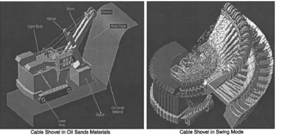
Cable Shovel Structural Components
The cable shovel is designed specifically to excavate and load materials in surface mining operations. This shovel has large breakout forces, lower maintenance, and production costs and higher economic useful life. The excavator’s high availability and utilization factors results in efficient production operations. Fig. 2 illustrates the structural components of this shovel. It uses electric motors, gear reducers, drums and wire ropes to actuate the mo-tions required for digging, loading and propelling. The capacity of these machines is typically 25 m3共33 yd3兲 to 63 m3共82 yd3兲 for
standard rock applications. The cable shovel consists of three major assemblies: The lower frame, upper frame, and the attach-ment. The lower frame provides a stable base for the machine and includes the propel-drive and crawler system. The upper frame provides a platform for the hoist and swing machinery, and for boom attachment, electronic control cabinets, operator’s cab, and supporting equipment. The attachment consists of the boom, crowd machinery, dipper handle, and dipper. The dynamics of this shovel includes propel, crowding, and retraction 共reverse crowd-ing兲, digging, loaded and empty swinging and dumping. These dynamic processes must be coordinated to ensure efficient oper-ating performance within a constrained environment 共P&H Mining 2003兲.
Dynamic Modeling of Cable Shovel Excavator
The cable shovel dynamic function comprises three major com-ponents, including inertia matrix, Coriolis and centripetal force effects and gravity effects. This dynamic function must be equiva-lent to the difference between the breakout force 共from equip-ment兲 and the resistive force due to formation. Thus, the dynamic equation for the cable shovel excavators is given by
D共⌰兲⌰¨ + C共⌰,⌰˙兲⌰˙ + G共⌰兲 = F − Fload共Ft,Fn兲 共1兲
The digging path of the dipper is produced by the extension/ retraction of the handle 共crowd兲 and by the cable hoisting action as in Figs. 2 and 3. Dipper hoisting is accomplished by means of cables attached to the dipper, which pass over sheaves at the boom point and spool on a deck mounted powered drum. The
Fig. 1. Sensor-vision system in the ISE technology
INTERNATIONAL JOURNAL OF GEOMECHANICS © ASCE / JANUARY/FEBRUARY 2008 / 3
crowd action is produced either by cables or a direct rack and pinion gear drive 共P&H Mining 2003兲. In Fig. 3, XWYWZW
⫽coordinates at the base and upper structures of the shovel,
O0X0Y0Z0, O1X1Y1Z1, and O2X2Y2Z2⫽respective coordinates of
the boom, crowd arm, and dipper. It is considered that the upper structures of the cable shovel are fixed, and thus, the kinematics and dynamic models of the shovel excavator are mainly related to crowd arm and dipper 共Koiva 1994; Koivo et al. 1996; Vaha and Shibniewski 1993.
The dynamic equations can be obtained by applying either the Lagrange method or iterative Newton–Euler method. The iterative Newton–Euler method is used because the iterative formulation lends itself to efficient software implementation, which is of im-portance for real-time simulation and parameter estimation 共Frim-pong and Hu 2004; Frim共Frim-pong et al. 2003; Daneshmend et al. 1993兲. Also, it provides detailed information on all links and joints, which is useful in stress and/or strength analysis of com-ponents. The Newton–Euler dynamic algorithm for computing the crowd force and the hoist torque comprises two parts. First, the velocities and accelerations are iteratively computed from the crowd arm to the dipper and the Newton–Euler equations are applied to each of them. Second, the interactive forces and torques and joint actuator torques are computed recursively from dipper back to crowd arm 共Craig 1986兲. The detailed mathemati-cal models for the cable shovel kinematics and dynamic models are outlined next in sections and in the Appendix.
Cable Shovel Kinematics
The shovel kinematics models are obtained for the front-end as-sembly, which comprises the boom, crowd arm, hoist rope, and dipper components as illustrated in Fig. 3. The angular and linear displacements, velocities and acceleration are established for the shovel base, boom, crowd arm, bucket, and the cutting edge of the dipper as illustrated in the Appendix. The Newton–Euler formu-lations are obtained for the outward and inner iterations as illus-trated in the Appendix. The equations of the outward iterations govern the motion of the forward assembly when it is being ex-tended to begin the excavation process. An empty dipper, higher angular and linear displacements and velocities and smaller mo-ments about the centers of rotation characterize this motion. The equations of the inward iterations govern the motion of the for-ward assembly when it is being retracted after the excavation
process. A loaded bucket, relatively slower angular and linear displacements and velocities and higher moments about the cen-ters of rotation characterize this motion.
Cable Shovel Dynamics
The shovel dynamic models are obtained for the front-end assem-bly in Fig. 3. The dynamic models use the results of the kinemat-ics as input to develop the models for inertial force, moments and resistive force. The active forces are used to generate the breakout forces required for the excavation process. The breakout force must exceed the resistive force for the formation to be removed from in situ. The resistive force is a resultant of the tangential and normal force incident on the plane of excavation as illustrated in Figs. 4 and 9. The resulting moments from the active forces and the centers of rotation about various joints are important in the overall shovel performance. The dynamic models are also devel-oped for outward or backward and inner or inward iterations to examine the dynamics of the excavation process in the extension,
Fig. 3. Elements of shovel dynamics 共adapted from Frimpong et al.
2003兲
excavation and retraction phases 共Araya et al. 1998兲. The details of the dynamic models are presented in the appendix section.
Numerical Validation of Cable Shovel Dynamics
A scaled cable shovel model is used to validate the dynamic mod-els in this study. The main geometry and physical data for the simulated shovel are listed in Table 1. The digging trajectory in Fig. 5 is first generated based on the physical and mechanical properties of the material being excavated using the reference coordinate system共XW, YW, ZW兲 in Fig. 3. Fig. 3 shows the
trajec-tory for completing the digging section of a working cycle using this reference coordinate. The moments of inertia for the dipper and the dipper handle are considered at the mass center for each element. The length of the handle is the length between the end of the handle and the handle-dipper joint. The length of the dipper is the length between the handle-dipper joint and end of the dipper teeth. The following discussions are based on the results from detailed experimentation of the cable shovel simulator under vari-ous operating regimes.
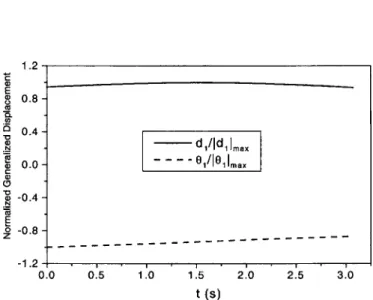
Figs. 6–8 show the change of 共d1, 1兲, 共d˙1, ˙1兲, and 共d¨1, ¨1兲
with time t, respectively. The vertical axes, in Figs. 6–8, have been normalized for a comparative purpose. In Fig. 6, the linear displacement of the crowd arm, d1, advances at first, experiences a maximum resistive force around the middle of the path profile and then retracts following the given digging profile, whereas the angular displacement of the crowd arm, 1, always increases with
time. Although 1is increasing constantly, its rate of change, 1, is not constant as illustrated in Fig. 7. It has a maximum around the path midpoint. For the crowd arm advance rate, d1, it is
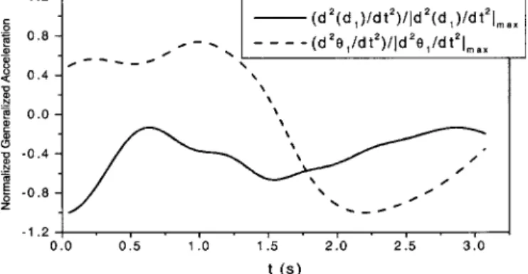
de-creasing constantly as shown in Fig. 7. The crowd arm advance acceleration, d¨1, and the angular acceleration, ¨1, are more
com-plex for the given digging path profile. The two accelerations increase and then decrease during the first half of the digging path and reverse for the latter half of the path. Figs. 6–8 also show that the crowd arm linear and rotational kinematics have different trends. It is important for planning engineers and operators to understand and control the machine kinematics to ensure efficient execution of the shovel trajectory within the limiting design and field constraints.
Table 1. Main Shovel Structural Data for Scaled Cable Shovel
Part Length 共m兲 Mass 共kg兲 Inertia moments共kg m2兲
Handle 11.888 65,800 7.749E + 5 Dipper 5.800 24,500 6.458E + 4 Bucket capacity 30.6 m3
Fig. 5. A trajectory for a shovel dipper tip
Fig. 6. Normalized linear共d1兲 and angular 共1兲 displacements with
time
Fig. 7. Normalized linear共d˙1兲 and angular 共˙1兲 velocities with time Fig. 4. Interaction between dipper and environment
INTERNATIONAL JOURNAL OF GEOMECHANICS © ASCE / JANUARY/FEBRUARY 2008 / 5
The crowd arm for the given digging trajectory has a much smaller change than that of the arm rotation, indicating a pre-dominant rotation effect in the inertial part. It is also noted that there are some erratic behaviors, especially in d¨1and ¨1, which
are attributed to the time differential of d1and 1. When d1, d˙1, d¨1,
1, ˙1, and ¨1are determined for each time, the normalized force
and torque can be calculated, and their behavior with time is shown in Fig. 9. Fig. 9 shows that the crowding inertial force increases continuously and has a much bigger range. It indicates that the inertial force mainly comes from the rotation part. How-ever, the torque requirements stay relatively constant, which indi-cates an efficient utilization of the breakout force requirements. Based on the Zelenin et al. 共1985兲 model, the resistive force ac-cording to the current trajectory is calculated and shown in Fig. 10. Fig. 10 shows that the digging force is divided into three phases in a digging cycle: gradual increase, reaching a maximum and a gradual decrease to zero. Finally, F may be obtained from Eq. 共1兲 as all other terms are already determined. Then the rela-tionship between the crowd force and hoist torque from crowd and hoist motors and the resistance force Frmay be established.
Thus, by measuring the crowd force and hoist torque, one can know the current resistance force from material diggability. Thus, from this analysis, the efficient breakout force, given certain dig-gability index, can be established and used for planning and ex-ecuting different material excavation. This is a major contribution to large-scale costly excavation of material in surface mining operations.
Optimum Shovel Performance. The results of the optimized machinery–formation interactions define the envelope for opti-mum digging performance. As illustrated by equations 共24兲, 共25兲, and 共27兲, the formation resistant force depends on several vari-ables that govern the geometry of machine–formation interac-tions. For efficient excavation in this paradigm, the results show that the normalized force, Fr, must be controlled based on Fig. 10. Given the maximum Frbased on the formation, the actual profile of the force required to overcome the formation resistance must increase from 0.25 to 1.63 s during the digging cycle and de-crease with same gradient in a parabolic form as illustrated in Fig. 10. The normalized linear and angular displacement, velocity and acceleration and inertia force and torque profiles must also follow Figs. 6–9, respectively, for optimum excavation.
Conclusions
Dynamic models of cable shovel excavators have been derived for the main functional components 共crowd arm and the dipper兲 as free body diagrams using an iterative Newton–Euler method. The responses from a given digging trajectory are predicted using a case study. The shovel kinematics results provide the optimum angular and linear displacements, velocities and acceleration for effective engagement of the formation by the dipper teeth. The dynamic models also yield the appropriate reactive forces, mo-ments and torque, which are required for generating the required breakout forces given certain material diggability index for effi-cient excavation. Further research is required to characterize, model and simulate the interactions between the shovel and the mining environments. This will eventually enable complete simu-lation of the shovel operation, as well as, ore bench digging con-ditions assessment based on on-line data measurements from the main functional components of a shovel excavator. These results will form the basis for developing the intelligent shovel excava-tion technology.
Acknowledgments
The writers express their gratitude to the Robert H. Quenon Endowment, University of Missouri-Rolla, for financial support of this research.
Fig. 8. Normalized linear 共d¨1兲 and angular 共¨1兲 accelerations with
time
Fig. 9. Normalized inertial force and torque with time
Notation
The following symbols are used in this paper:
Cij ⫽ 共i, j兲 element of Coriolis and centripetal
torque C共,˙兲˙;
C0 ⫽ compactness and cutting resistance index; C共⌰,⌰˙兲 ⫽ generalized Coriolis and centripetal torque;
c1, s1 ⫽ cos 1, sin 1respectively;
ci, si ⫽ cos iand sin i共i, j兲, respectively;
cij, sij ⫽ cos共1+ j兲 and sin共i+ j兲共i, j兲, respectively;
Dij ⫽ 共i, j兲 element of inertia matrix D共兲;
D共⌰兲 ⫽ generalized inertia matrix; d ⫽ cutting plate thickness;
di ⫽ offset distance of the gravity center in link i;
d1, d˙1, d¨1 ⫽ displacement, linear velocity and acceleration
of crowd arm;
ez ⫽ tool plate thickness;
F ⫽ cable shovel’s breakout force;
Fload共Ft, Fn兲 ⫽ resistive force due to the formation being
excavated by the shovel dipper;
Fn ⫽ normal reaction force;
Fr ⫽ loading force acting on dipper from the soil;
Fr ⫽ resistive forces from formation material;
Ft ⫽ tangential reaction force;
1F
1 ⫽ inertial force at the center of the crowd arm; 2F
2 ⫽ inertial force at the center of the dipper; f31, f32 ⫽ respective x and y components of the
interaction force between soil and dipper tip;
Gi ⫽ ith component of gravity torque G共兲;
G共⌰兲 ⫽ generalized gravity torque;
Ii ⫽ moment of inertia of link I about centroidal
axis parallel to ziaxis;
Izz1 ⫽ moment of inertia of crowd arm about
centroidal axis parallel to z1axis;
Izz2 ⫽ moment of inertia of dipper about centroidal
axis parallel to z2axis; kzi ⫽ unit vector on the ziaxis;
kz ⫽ index for the type of cutting;
L1 ⫽ length of crowd arm from pivotal point to the
connection point between arm and dipper 共L1= l1兲;
L2 ⫽ length between dipper tip and connect point
of arm and dipper共L2= l2兲; mi ⫽ mass of link i;
m1 ⫽ mass of crowd arm; m2 ⫽ mass of dipper; 1N
1 ⫽ torque at the center of the crowd arm; 2N
2 ⫽ torque at the center of the dipper; 0
P1 ⫽ location vector for the rotation point of the
crowd arm;
1P
c1 ⫽ location vector for the center of the mass of
the crowd arm;
0
1R ⫽ transformation matrix from base frame to the
crowd arm based coordinate;
ri ⫽ length of line segment between Oi−1 and Oi,
i= 1 , 2 , 3;
s ⫽ cutting edge index;
1
v˙c
1 ⫽ linear acceleration at the center of the crowd
arm;
2
v˙c
2 ⫽ linear acceleration at the center of the dipper;
w ⫽ cutting tool width;
 ⫽ angle the rupture failure plane makes with the horizontal;
⌫ij ⫽ 共i, j兲 element of control matrix ⌫共兲; ⌰ ⫽ vector of generalized variables;
b ⫽ angle between dipper bottom and X4axis;
dg ⫽ angle between dipper edge and horizontal line
共digging angle兲;
i ⫽ angle between riand x axis of a local coordinate共i=5,6,7,8,9,10,11兲;
i, ˙i, ¨i ⫽ angular, velocity and acceleration of joint i共i
= 1 , 2 , 3兲, respectively;
˙1 ⫽ rotation angular velocity of the crowd arm based coordinate relative to the base frame; 1, ˙1, ¨1 ⫽ angular, velocity and acceleration of crowd
arm, respectively;
0
0 ⫽ angular velocity of the shovel base; 0˙
0 ⫽ angular acceleration of the shovel base; 1
1 ⫽ angular velocity at the center of the crowd
arm;
1˙
1 ⫽ angular acceleration at the center of the
crowd arm;
2
2 ⫽ angular velocity at the center of the dipper;
and
2˙
2 ⫽ angular acceleration at the center of the
dipper.
Appendix. Cable Shovel Dynamic Equations
The following equations describe the cable shovel kinematics and dynamic models in a typical surface mining operating environ-ment. The base of the shovel is fixed, and hence it does not rotate during operation, resulting in
0 0= 0,
0˙
0= 0 共2兲
As an example, the outward iteration for crowd arm is demon-strated. This procedure includes the calculation of the angular velocity, angular acceleration, and the linear acceleration at the center of the crowd arm, respectively, in
1 1=0 1R0 0+ ˙11Zˆ1=
冢
c1 s1 0 − s1 c1 0 0 0 1冣冢
0 0 0冣
+冢
0 0 ˙1冣
=冢
0 0 ˙1冣
共3兲 1˙ 1=0 1 R00⫻ ˙11Zˆ1+0 1 R0˙0+ ¨11Zˆ1=冢
c1 s1 0 − s1 c1 0 0 0 1冣冢
0 0 0冣
⫻冢
0 0 ˙1冣
+冢
c1 s1 0 − s1 c1 0 0 0 1冣冢
0 0 0冣
+冢
0 0 ¨1冣
=冢
0 0 ¨1冣
共4兲INTERNATIONAL JOURNAL OF GEOMECHANICS © ASCE / JANUARY/FEBRUARY 2008 / 7
1 v˙1=01R共0˙0⫻0P1+00⫻共00⫻0P1兲 +0v˙0兲 + 211⫻ d˙11Zˆ1 + d¨11Zˆ1 =
冢
c1 s1 0 − s1 c1 0 0 0 1冣冦冢
0 0 0冣
⫻冢
0 0 0冣冧
+冢
c1 s1 0 − s1 c1 0 0 0 1冣
⫻冦冢
0 0 0冣
⫻冢冢
0 0 0冣
⫻冢
0 0 0冣冣
+冢
0 g 0冣冧
+ 2冢
0 0 ˙1冣
⫻冢
d˙1 0 0冣
+冢
d¨1 0 0冣
=冢
gs1+ d¨1 gc1+ 2d˙1˙1 0冣
共5兲 1 v˙c 1= 1˙ 1⫻1Pc1+ 1 1⫻共11⫻1Pc1兲 + 1 v˙1 =冢
− d1˙12+ d¨1+ gs1 d1¨1+ 2d˙1˙1+ gc1 0冣
共6兲It also involves the calculation of the torque and the inertial force at the center of the crowd arm, respectively, in
1N 1=c1I11˙1+11⫻c1I111=
冢
0 0 0 0 0 0 0 0 Izz1冣
冢
0 0 ¨1冣
+冢
0 0 ˙1冣
⫻冢
冢
0 0 0 0 0 0 0 0 Izz1冣
冢
0 0 ˙1冣冣
=冢
0 0 Izz1¨1冣
共7兲 1F 1= m11v˙c 1=冢
− m1d1˙1 2+ m 1d¨1+ m1gs2 m1d1¨1+ 2m1d˙1˙1+ m1gc1 0冣
共8兲The angular velocity at the center of the crowd arm is necessary for estimating the Coriolis and centripetal effects of the crowd arm and dipper assembly. Using the gravity effect共0v˙
0= gzˆ0兲, Eq.
共5兲 can be reformulated as Eq. 共6兲. The linear acceleration at the center of the crowd arm is used to calculate the inertial force of the crowd arm and dipper assembly. Euler’s equation is used to calculate the torque at the mass center of the crowd arm, as illus-trated in Eq. 共7兲. Newton’s equation is applied here to calculate the inertial force at the mass center of the crowd arm in Eq. 共8兲. The same procedure can be applied to the dipper to calculate its angular velocity, angular acceleration, linear acceleration, the torque at the center of the dipper, and the inertial force at the center of the dipper, as illustrated, respectively, in
2 2=1 2 R11+ ˙22Zˆ2=
冢
1 0 0 0 1 0 0 0 1冣冢
0 0 1冣
+冢
0 0 0冣
=冢
0 0 ˙1冣
共9兲 2˙ 2=12R11⫻ ˙22Zˆ2+12R1˙1+ ¨22Zˆ2 =冢
1 0 0 0 1 0 0 0 1冣
冢
0 0 ˙1冣
⫻冢
0 0 0冣
+冢
1 0 0 0 1 0 0 0 1冣
冢
0 0 ¨1冣
+冢
0 0 0冣
=冢
0 0 ¨1冣
共10兲 2 v˙2=12R共1˙1⫻1P2+11⫻共11⫻1P2兲 +1v˙1兲 + 222⫻ d˙22Zˆ2+ d¨22Zˆ2=冢
− l1˙1 2+ d¨ 1+ gs1 l1¨1+ 2d˙1˙1+ gc1 0冣
共11兲 2 v˙c 2= 2˙ 2⫻ 2 Pc2+ 2 2⫻共 2 2⫻ 2 Pc2兲 + 2 v˙2 =冢
−共l1+ d2兲˙1 2+ d¨ 1+ gs1 共l1+ d2兲¨1+ 2d˙1˙1+ gc1 0冣
共12兲 2 N2=c2I2 2˙ 2+ 2 2⫻c2I2 2 2 =冢
0 0 0 0 0 0 0 0 Izz2冣
冢
0 0 ¨1冣
+冢
0 0 ˙1冣
⫻冢
冢
0 0 0 0 0 0 0 0 Izz4冣
⫻冢
0 0 ˙1冣冣
=冢
0 0 Izz2¨1冣
共13兲 2 F2= m22v˙c 2=冢
− m2共l1+ d2兲˙1 2+ m 2d¨1+ m2gs1 m2共l1+ d2兲¨1+ 2m2d˙1˙1+ m2gc1 0冣
共14兲Having computed the forces and torques acting on the crowd arm and the dipper, it now remains to calculate the joint torques which will result in these net forces and torques being applied to the crowd arm and the dipper. This is achieved by writing force and moment balance equations based on free body diagrams of the crowd arm and the dipper. The inward iteration for the dipper is first calculated as 2f 2=23R3f3+2F2 =
冢
− m2共l1+ d2兲˙1 2+ m 2d¨1+ f31c3− f32s3+ m2gs1 m2共l1+ d2兲¨1+ 2m2d˙1˙1+ f31s3+ f32c3+ m2gc1 0冣
共15兲Eq. 共15兲 is the force balance equation for the dipper. The torque balance equation for the dipper is given by 2 n2= 2 N2+3 2 R3n3+ 2 Pc2⫻ 2 F2+ 2 P3⫻3 2 R3f3=
冢
0 0 Izz2¨1+ m2共l1+ d2兲d2¨1+ 2m2d2d˙1˙1+ m2gd2c1+ f31l2s3+ f32l2c3冣
共16兲 Following the same procedure, the inward iteration for crowd arm is given by1 f1=1 2 R2f2+ 1 F1=
冢
−共m1d1+ m2共l1+ d2兲兲˙1 2+共m 1+ m2兲d¨1+ f31c3− f32s3+共m1+ m2兲gs1 共m1d1+ m2共l1+ d2兲兲¨1+ 2共m1+ m2兲d˙1˙1+ f31s3+ f32c3+共m1+ m2兲gc1 0冣
共17兲 1n 1= 1N 1+2 1R2n 2+ 1P c1⫻ 1F 1+ 1P 2⫻2 1R2f 2 =冢
0 0 共Izz1+ Izz2兲¨1+ m2共l1+ d2兲d2¨1+ 2m2d2d˙1˙1冣
+冢
0 0 m2gd2c1+ f31l2s3+ f32l2c3冣
+冢
0 0 m1d12¨1+ 2m1d1d˙1˙1+ m1gd1c1+ m2共l1+ d2兲l1¨1冣
+冢
0 0 2m2l1d˙1˙1+ f31l1s3+ f32l1c3+ m2gl1c1冣
共18兲 Eqs. 共17兲 and 共18兲 are the respective force and moment balance equations for the crowd arm. Finally, the equations for the joint force and torque are obtained inF1=共m1+ m2兲d¨1− m1d1˙12− m2共l1+ d2兲˙12
+ f31c3− f32s3+共m1+ m2兲gs1 共19兲
1=共Izz1+ Izz2兲¨1+共m1d12+ m2共l1+ d2兲2兲¨1
+ 2共m1d1+ m2共l1+ d2兲兲d˙1˙1+ f31共l1+ l2兲s3+ f32共l1+ l2兲c3
+共m1d1+ m2共l1+ d2兲兲gc1 共20兲
For cable shovels, ⌰ is equal to兵d11其T. From Eqs. 共19兲 and 共20兲, D共⌰兲, C共⌰,⌰˙兲, G共⌰兲, and Fload共Ft, Fn兲 can be determined,
re-spectively, as D共⌰兲 =
冋
m1+ m2 0 0 Izz1+ Izz2+ m1d1 2+ m 2共l1+ d2兲2册
共21兲 C共⌰,⌰˙兲 =冋
0 共m1d1+ m2共l1+ d2兲兲˙1 2共m1d1+ m2共l1+ d2兲兲˙1 0册
共22兲 G共⌰兲 =冋
共m1+ m2兲gs1 共m1d1+ m2共l1+ d2兲兲gc1册
共23兲 Fload共Ft,Fn兲 =冋
f31c3− f32s3 f31共l1+ l2兲s3+ f32共l1+ l2兲c3册
共24兲 The dipper-environment geometrical relationships are illustrated in Fig. 4. Therefore, Eq. 共24兲 can be written asFload共Ft,Fn兲 =
冤
1 0 0 1 1 0 1 1 1冥
⫻冦
r4共− Ftsin b− Fncos b兲 r3共− Ftsin共dg− 2− 3兲 − Fncos共dg− 2− 3兲兲 r2共− Ftsin共dg− 2兲 − Fncos共dg− 2兲兲冧
共25兲 From Figs. 4 and 9, it is noted that arm crowd and arm rotation have different trends. f31and f32can be related to Fras inf31= − Frcos共1− dg+ 0.1兲
f32= − Frsin共1− dg+ 0.1兲 共26兲
Zelenin et al. 共1985兲 provided a basis for estimating the resistive force, Fr, as shown in the following equation and Fig. 9:
Fr= 10C0d1.35共1 + 2.6w兲共1 + 0.0075兲共1 + 0.03s兲ezkz 共27兲
References
Araya, H., Kakuzen, M., Kimura, N., and Hayashi, N. 共1988兲. “Auto-matic control system for hydraulic shovels.” Proc., U.S.–Japan Symp.
on Flexible Automation—Crossing Bridges: Advances in Flexible Au-tomation and Robotics, Minneapolis.
Awuah-Offei, K. 共2005兲. “Dynamic modeling of cable shovel formation interactions for efficient oil sands excavation.” Ph.D. dissertation, Univ. of Missouri-Rolla, Rolla, Mo.
Craig, J. J. 共1986兲. Introduction to robotics: Mechanics and control, Addison-Wesley, Reading, Mass.
Daneshmend, L., Hendricks, C., Wu, S., and Scoble, M. 共1993兲. “Design of a mining shovel simulator.” Innovative mine design for the 21st
Century, Baiden and Archibald, eds., Kingston, Canada, 551–561. Frimpong, S., and Hu, Y. 共2004兲. “Parametric simulation of shovel-oil
sands interactions during excavation.” Int. J. Surf. Mining,
Reclama-tion & Environ., in press.
Frimpong, S., Hu, Y., and Szymanski, J. 共2003兲. “Intelligent cable shovel excavation in surface mining.” SME Conf. and Annual General
Meet-ing, Cincinnati.
Frimpong, S., Szymanski, J., Pedrycz, W., and Gao, Y. 共2001兲.
“Intelli-INTERNATIONAL JOURNAL OF GEOMECHANICS © ASCE / JANUARY/FEBRUARY 2008 / 9
gent shovel excavation in varying oil sands formation and bitumen content.” Proposal, submitted to COURSE, Univ. of Alberta, Edmon-ton, Alta., Canada.
Hendricks, C., Daneshmend, L., Wu, S., and Scoble, M. 共1993兲. “Design of a simulator for productivity analysis of electric mining shovels.”
Proc., 2nd Int. Symp. on Mine Mechanization and Automation, Lulå, Sweden, 329–336.
Koivo, A. J. 共1994兲. “Kinematics of excavators 共backhoes兲 for transfer-ring surface material.” J. Aerosp. Eng., 7共1兲, 17–32.
Koivo, A. J., Thoma, M., Kocaoglan, E., and Andrade-Cetto, J. 共1996兲.
“Modeling and control of excavator dynamics during digging opera-tion.” J. Aerosp. Eng., 9共1兲, 10–18.
P&H Mining. 共2003兲. Peak performance practices: Excavator selection
for high production, low-cost operations, Harnischfeger Corporation, Milwaukee.
Vaha, P. K., and Shibniewski, M. J. 共1993兲. “Dynamic model of excava-tor.” J. Aerosp. Eng., 6共2兲, 148–166.
Zelenin, A. N., Balovnev, V. I., and Kerov, I. P. 共1985兲. Machines for