Basic communication framework for a robotic device for the inspection of nuclear reactor piping structures
Texte intégral
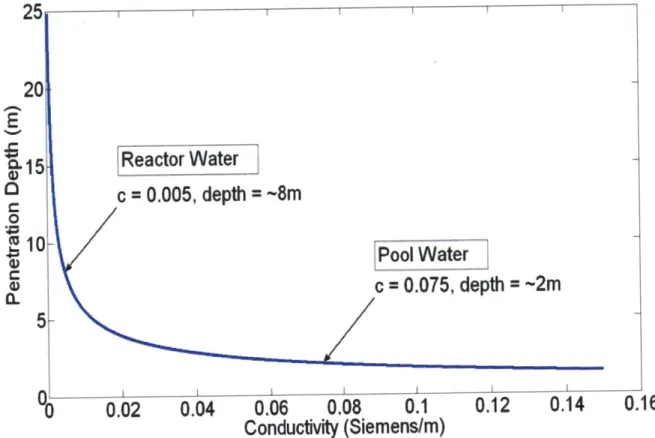
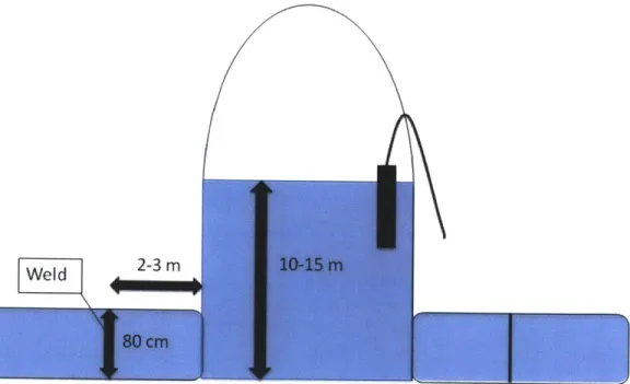
Figure


Documents relatifs
(Не случаен, ведь, тот факт, что королевна родилась на башне: она вообще не подвержена искушениям нижнего мира, и поэтому, когда нисходит с башни для исполнения
In a similar fashion, the figure of the writer in In the Memorial Room is diffused through different characters in the novel: Harry of course, but also the national heritage
The five ways to be theoretical pertain to grounding, referencing, study design and analysis, interpretation of findings, and impact (Table
Computational Wisdom is seen here as a system of systems, where the technology augments the human in one direction, whilst being augmented by the human in another, and finally
The following people contributed to the preparation and revision of the report: Peter Beznec, Director, Centre for Health and Development Murska Sobota, Slovenia; Luca
more impartial and longer lasting. Only then do we get to work on changing behaviour as a means of reinforcing the impact of the priority measures that have been taken. Most of
But something that is the case is (is nothing other than) something that can be truly thought, and as such it is located in the realm of sense. If this placing of things that are
εἰ δὴ τὸ ὂν καὶ τὸ ἓν ταὐτὸν καὶ μία φύσις τῷ ἀκολουθεῖν ἀλλή- λοις ὥσπερ ἀρχὴ καὶ αἴτιον, ἀλλ’ οὐχ ὡς ἑνὶ λόγῳ δηλού- μενα (δι- αφέρει δὲ οὐθὲν οὐδ’ ἂν ὁμοίως
