Analysis of Parasitic Losses in Heavy Duty Diesel Engines
by
Christopher Joseph James B.S. Mechanical Engineering Northeastern University, 2010
SUBMITTED TO THE DEPARTMENT OF MECHANICAL ENGINEERING IN PARTIAL FULFILLMENT OF THE REQUIREMENTS FOR THE DEGREE OF
MASTER OF SCIENCE IN MECHANICAL ENGINEERING AT THE
MASSACHUSETTS INSTITUTE OF TECHNOLOGY JUNE 2012
@ 2012 Massachusetts Institute of Technology All Rights Reserved
/\ P
ARCHIVES
MASSACHUSETTS INST E OF TECHNOLOGYJUN
2
8
2012
LIBRARIES
14 4 Signature of A uthor... ... ...Department of Mechanical Engineering
May 25, 2012
Certified by..
..
...
Victor W. Wong
Principal Research Scientist and Lecturer in Mechanical Engineering
Thesis Supervisor
Accepted by...
..-
..
...
David E. Hardt Chairman, Department Committee on Graduate StudentsAnalysis of Parasitic Losses in Heavy Duty Diesel Engines
by
Christopher Joseph James
Submitted to the Department of Mechanical Engineering on May 25, 2012 in Partial Fulfillment of the Requirements for the Degree of Master of Science in
Mechanical Engineering
Abstract
Fuel economy of large, on-road diesel engines has become even more critical in recent years for engine manufactures, vehicle OEMs, and truck operators, in view of pending CO2 emission
regulations. Demands for increased fuel economy are coupled with corresponding improvements in engine performance, durability, and emissions. This project centers on resolving the adverse effects on engine wear, durability, emissions, and oil consumption that often accompany traditional low-friction concepts. A detailed analysis of the sources of friction within a heavy-duty diesel engine was undertaken and empirical data on engine friction and component wear was collected from industry as well as from studies in literature.
The use of thermal barrier coatings (TBC) was investigated as a novel approach to strategically increase cylinder liner temperatures in order to reduce power cylinder friction. By coating selected parts of the liner where piston speeds are high, local liner temperature is raised and local lubricant viscosity decreased in that region. In the mid-stroke, the piston is in the hydrodynamic lubrication regime, and high surface speeds generate the majority of the power cylinder work losses which can be reduced through reduced lubricant viscosity. By coating the liner in selected regions only, top dead center temperatures are mostly unaffected thereby minimizing any increase in cylinder liner wear. This approach is expected to maximize friction reduction while minimizing risk to other engine components or increasing component wear rates.
A simulation was developed to model the primary physical processes that occur in a complete four stroke engine cycle. Calculations included work done by the piston, mass flow rates through the intake and exhaust valves, heat release during combustion, and heat transfer rates. The results demonstrate the potential to decrease power cylinder between 15% and 30% depending on coating thickness and application zone. This corresponds to approximately a 0.5% to 1% improvement in vehicle fuel economy. Additional fuel economy benefits from the TBC are expected from increased exhaust gas enthalpy and reduced liner heat rejection. This strategic thermal management approach within the engine has very high potential to increase engine efficiency while maintaining the performance and durability demanded in the HD engine market. Thesis Supervisor: Victor W. Wong
Acknowledgements
My time at MIT has been a memorable, challenging, and extremely rewarding experience.
Central to my success here at MIT has been the influence of a number of people, to whom I've
tremendously grateful. I would like to thank the following people for their help in the completion
of this project
First I would like to acknowledge and thank my advisor, Dr. Victor Wong, for his support and
guidance throughout my time here at MIT. His vast experience in engine design and modeling
exposed me to an exciting field of research and knowledge. The analytical skills gained through
my research will prove invaluable in any profession.
This project would not have been possible without the support of my project sponsor, Detroit
Diesel/Daimler Trucks North America. I would like to thank Kevin Sisken, Dave Maietta, and
Dennis Krawczak for their support throughout the project and their expertise in engine
component design.
I would like to thank the students of the Sloan Automotive Laboratory for providing an
engaging, and often times entertaining work environment. I would like to thank Yin-Chun Wang
for providing interesting conversation and a necessary distraction from research. Thomas Martins
and Troy Niekamp for their friendship and office comradery. Justin Ketterer for the hours spent
on various homework assignments and study sessions. Dr. Alex Sappok and Dr. Carl Justin
Kamp for their guidance throughout my time here at MIT. Finally no acknowledgment of the
Sloan Lab would be complete without thanking Janet Maslow for her tireless efforts to keep the
lab running smoothly.
I would like to extend my sincerest thanks to my family and friends for their support. I am
especially grateful to my parents for their unwavering support, guidance, and encouragement in
my personal, academic, and professional endeavors. Most importantly, I am thankful for the love
and support of my fiancee, Emily, whose daily encouragement and understanding has made my
time here at MIT much more enjoyable.
Table of Contents
Abstract ...
3
Acknowledgem ents...
5
Table of Contents...7List of Figures...
11
List of Tables ... 13 Nom enclature... 15 1. Introduction ... 171.1 Diesel Engine Principles ... 18
1.1.1 Typical Application of Diesel Engines ... 19
1.1.2 Advantages of Diesel Engines ... 21
1.1.3 D isadvantages of Diesel Engines... 22
1.2 Regulation of Heavy Duty On-road Diesel Engines ... 23
1.2.1 Em issions Regulation... 23
1.2.2 Em ission Control Strategies... 25
1.2.3 Fuel Econom y Standards ... 26
1.3 The M otivation to Reduce Engine Friction... 27
1.4 Sources of Friction in Diesel Engines ... 29
1.4.1 Overview of M ajor Engine System s ... 30
1.4.2 Quantifying Friction Losses... 32
1.4.3 Typical Friction Distribution in a HD Diesel Engine ... 34
1.5 Scope of Current W ork ... 38
2 Friction Analysis... 39
2.1 Lubrication Regim es in an Engine ... 39
2.2 Lubricant properties ... 41
2.2.1 Lubricant Additives ... 42
2.2.2 Viscosity Tem perature Relationship... 43
2.2.3 Viscosity and Shear Rate Relationship... 44
2.3 W ear ... 45
3.1
Numerical Friction M odels ...
48
3.1.1
Crankshaft Numerical Friction M odels ...
48
3.1.2
Power Cylinder Numerical Friction M odels...
50
3.2
Empirical Friction M odels ...
55
3.3
Empirical Friction M odels Applied to HD Diesel Engines...
66
3.3.1
Crankshaft...
66
3.3.2
Power Cylinder ...
67
3.3.3
Auxiliary Components ...
68
3.3.4
Summary...
69
4 Local Oil Viscosity and Friction Reduction -Study of Cylinder Liner Thermal Barrier Coatings ... 71
4.1 Previous Studies of Thermal Barrier Coatings in Diesel Engines ... 72
4.1.1 Effects of TBC and LHR on Engine Emissions... 74
4.1.2 Effects of TBC and LHR on Engine Performance Parameters... 75
4.2 Thermal Barrier Coating Properties ... 76
4.3 Motivation for Research in Thermal Barrier Coatings for Super Truck Project... 77
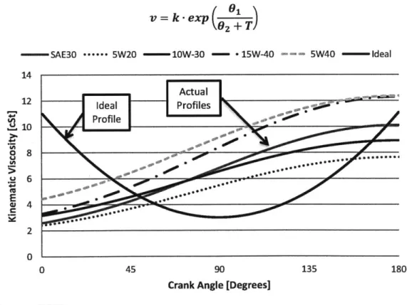
4.3.1 Power Cylinder Lubrication... 77
4.4 M odeling Approach and Details ... 81
4.4.1 Overview of M odel... 81
4.4.2 M odifications to M odel... 86
4.5 Results and Discussion... 89
4.5.1 Study of Thermal Barrier Coating Thickness and Application Zone on Cylinder Liner Temperature ... 89
4.5.2 Comparison of Natural Convection Combined Thermal Barrier Coatings on Selected Parts of the Cylinder Liner... 94
4.5.3 Study of Thermal Barrier Coating Thickness and Application Zone on Lubricant Kinematic Viscosity ... 97
4.5.4 Friction Reduction Potential of TBC... 102
4.5.5 Study of Thermal Barrier Coating Thickness and Application Zone on Coolant Heat Rejection and Exhaust Gas Enthalpy ... 110
4.5.6 Study of Thermal Barrier Coating Thickness and Application Zone on Engine Thermal Efficiency ... 115
4.6 Sum m ary of Therm al Barrier Coating Study ... 117
5 Conclusions ... 119
5.1 Continuing W ork... 121
W orks Cited ... 123
List of Figures
Figure 1.1 Sulzer RT96-C Diesel Engine [5]...
19
Figure 1.2 Reduction of PM and NOx Emissions Over Time [13] ...
25
Figure 1.3 Weekly U.S. No 2 Diesel Retail Prices 1995-2012 [19]...
28
Figure 1.4 United States Petroleum Consumption in the Transportation Sector [7] ...
29
Figure 1.5 Distribution of Total Energy in a Fired Engine [20]...
34
Figure 1.6 Distribution of Total Mechanical Losses of a Diesel Engine [20]...
35
Figure 1.7 Typical Distribution of Power Loss in the Power Cylinder [20]... 36
Figure 1.8 Typical Distribution of Piston Ring Friction [20]... 36
Figure 1.9 Flowchart of Friction Contributions by Component Group... 37
Figure 2.1 Regimes of Lubrication Shown on the Scale of Surface Asperities [23]... 39
Figure 2.2 Stribeck Curve... 40
Figure 2.3 Estimated Additive use for 2006 by additive type, North America ... 42
Figure 2.4 Cross Equation Lubricant Viscosity Shear Rate Dependence... 45
Figure 3.1 Lubricant Pressure Distribution in a Dynamically Loaded Journal Bearing... 50
Figure 3.2 Stribeck Curve for Power Cylinder Components ... 51
Figure 3.3 Forces and Moments Acting on the Piston [36]... 52
Figure 3.4 Model Layout for Each Piston Ring ... 54
Figure 3.5 Crankshaft Friction Model and Experimental Results ... 66
Figure 3.6 Crankshaft FMEP Analysis for SAE Oil Grades ... 67
Figure 3.7 Power Cylinder FMEP Analysis for SAE Oil Grades... 68
Figure 3.8 Oil Pum p FM EP... 69
Figure 3.9 Total Engine FMEP as a Function of Engine Speed ... 69
Figure 4.1 Dry and Wet Cylinder Liner Comparison [52]... 71
Figure 4.2 Thermal conductivity of 8% YSZ at Various Measuring Temperatures [59]... 76
Figure 4.3 Instantaneous Piston Velocity as a Function of Crank Angle ... 78
Figure 4.4 Cylinder Liner Wall Temperature Distribution... 79
Figure 4.5 Kinematic Viscosity of Lubricant on Cylinder Liner versus Ideal Case... 80
Figure 4.6 Geometry of Power Cylinder Without and With TBC... 82
Figure 4.7 Thermal Resistance Circuit ... 85
Figure 4.8 Diagram of Cylinder Liner Segments in Model... 87
Figure 4.9 Heat Transfer Element of Cylinder Liner... 88
Figure 4.10 Conventionally Cooled Cylinder Liner and Liner with TBC on Mid-Stroke ... 90
Figure 4.11 Liner Wall Temperature Woschni Correlation vs Model... 91
Figure 4.12 Liner Temperature Profile with TBC on Entire Liner... 92
Figure 4.13 Liner Temperature with TBC on Piston Mid-stroke (Segments 4,5,6)... 93
Figure 4.14 Liner Temperature with TBC on Segments 4 through 10 ... 94
Figure 4.15 Natural Convection Applied to Various Liner Segments... 95 Figure 4.16 Cylinder Liner Temperature Profile with Natural Convection on Bottom 30% of
Figure 4.17 Cylinder Liner Temperature Profile with Natural Convection on Bottom 20% of
Liner and TBC on M id-stroke... 96
Figure 4.18 Local Viscosity of 15W-40 with TBC on Entire Liner ... 97
Figure 4.19 Local Viscosity of 15W-40 with TBC on Liner Segments 4,5,6 ... 98
Figure 4.20 Local Viscosity of 15W-40 with TBC on Liner Segments 4 through 10... 98
Figure 4.21 Lubricant Viscosity with Natural Convection Applied to Liner Segments... 99
Figure 4.22 Lubricant Viscosity with Natural Convection Applied to Segments 9-10 and TBC from 4-8 ... 100
Figure 4.23 Lubricant Viscosity with Natural Convection Applied to Segments 8-10 and TBC from 4-7 ... 100
Figure 4.24 Power Cylinder Lubricant Viscosity over Engine Cycle for Different TBC and Natural Convection Applications... 101
Figure 4.25 Instantaneous Power Cylinder Friction Over Complete Engine Cycle ... 102
Figure 4.26 Cylinder Liner Segment Crank Angle Duration and Average Velocity... 103
Figure 4.27 Average Friction Force for Each Liner Segment ... 103
Figure 4.28 Average Friction Work Losses for Each Liner Segment... 104
Figure 4.29 Average Friction Power Losses for Each Liner Segment ... 104
Figure 4.30 Hydrodynamic and Boundary Friction Forces in the Ring Pack [42]... 105
Figure 4.31 Hydrodynamic and Boundary Friction FMEP for Varying Mean Lubricant V iscosities [42]... 106
Figure 4.32 Decrease in Liner Segment Friction Force for TBC Applications ... 107
Figure 4.33 Decrease in Liner Segment Friction Power Losses for TBC Applications ... 108
Figure 4.34 Reduction in Engine Friction for Various TBC Application Zones... 109
Figure 4.35 Coating Thickness and Type versus Exhaust Enthalpy... 111
Figure 4.36 Liner Heat Rejection for Different TBC Thickness and Application Zone ... 112
Figure 4.37 Liner Heat Rejection for Different TBC Thickness and Application Zone ... 113
Figure 4.38 Cylinder Gas Temperature versus Crank Angle... 114
Figure 4.39 Cylinder Liner Full Cycle Heat Transfer by Liner Segment... 114
Figure 4.40 Thermal Efficiency as a Function of TBC Thickness ... 115
List of Tables
Table 1.1 Federal Heavy Duty Diesel Engine Emission Regulations [12]... 24
Table 1.2 EPA and NHTSA Proposed Model Year 2017 Combination Trailer Standards ... 27
Table 4.1 Model Input Parameters for Engine Geometry, Timing, Fuel and Air Input ... 89
Table 4.2 TBC Parameters and Additional Model Inputs... 90
Table 4.3 Hydrodynamic Friction Weighting Factors ... 106 Table A.0.1 Lubricant Properties and Constants Used in Vogel and Cross Equations Various 131
Nomenclature
BDC -Bottom Dead Center
BMEP - Brake Mean Effective Pressure BSFC - Brake Specific Fuel Consumption CI - Compression Ignition
CI - Compression Ignition CO -Carbon Monoxide C02- Carbon Dioxide
DPF - Diesel Particulate Filter EGR - exhaust gas recirculation EHD -Elastohydrodyanmic
EPA -United States Environmental Protection Agency FMEP - Friction Mean Effective Pressure
GHG - Greenhouse Gas
GWP - Global Warming Potential HC - Hydrocarbons
HD -Heavy Duty
ICE -Internal Combustion Engine
IMEP - Indicated Mean Effective Pressure
IPCC - Intergovernmental Panel on Climate Change ISFC -Indicated Specific Fuel Consumption
LHR - Low Heat Rejection
NHTSA - National Highway Traffic Safety Administration NMHC -Non-Methane Hydrocarbons
OEM - Original Equipment Manufacturer OCR - Oil Control Ring
PM -Particulate Matter PM - Particulate Matter RPM -Revolutions Per Minute SCR -Selective Catalytic Reduction SI - Spark-Ignition
TBC - Thermal Barrier Coating TDC -Top Dead Center
VI - Viscosity Index VI - Viscosity Modifier
1. Introduction
Fuel economy in large, on-road diesel engines has become even more critical in recent years for
engine manufactures, vehicle OEMs, and for truck operators. Demands for increased fuel
economy are coupled with increased demands in engine performance and durability by
consumers. Additionally, more stringent emissions standards for particulate matter (PM),
nitrogen oxides (NO,), and non-methane hydrocarbon emissions (NMHC) have added significant
equipment to the vehicle and a corresponding engine efficiency penalty.
Vehicle fuel economy improvements are realized through a multitude of approaches, from
engine downsizing, improved vehicle aerodynamics, electrification, waste heat recovery, and
increased efficiency from existing vehicle systems. Fuel economy improvements in the engine
can be realized through mechanical design, advanced control systems, material improvements,
and friction reduction. Reductions in engine friction increase the brake mean effective pressure
(bmep) of the engine and reduce the brake specific fuel consumption (BSFC). Engine friction
reduction is accomplished through three primary methods: mechanical design of engine
components, material surface texture and coatings, and improvements in engine lubrication
performance.
The mechanical design of engine components dictates the friction surfaces in an engine; in
addition to the loading, surface speeds, and lubrication each engine component receives. Design
engineers have been improving mechanical designs since the first engines were developed.
Changes in the mechanical design of a production engine can be very challenging for a variety of
reasons including tooling, service, certification, and concern on overall system integrity. While
these barriers can be overcome, the cost and time to implement these changes may outweigh the
benefit.
Material surface texture and low friction coatings have led to improved performance, durability
and lower friction in internal combustion engines. Recent studies have used various cylinder
liner crosshatch patterns and angles in addition to micro texturing of the cylinder liner to mitigate
wear effects associated with lower viscosity lubricants [1]. Coatings and textures can be easily
the lifecycle of the engine. For class 8 trucks the B50 life, or the point at which half the engines
produced are still running and half require rebuild, is typically 1 million miles. These extremely
long life cycles make coating longevity of primary importance.
Engine lubricant provides critical protection and lubrication of engine components. Lubricant
properties and additives therefore have a vital role in engine performance and durability along
with the longevity of vehicle emission systems. Improvements in the engine lubrication system
to optimize mechanical conditions such as temperature, load, and shear rate as well as advanced
lubricant formulations can reduce engine frictional losses and improve performance.
Investigations into lubricant base stock, friction modifiers, anti-wear additives, high-temperature
high-shear (HTHS) properties, and viscosity modifiers (VM), to optimize the friction
characteristics of engine oil under various loading conditions can make notable improvements on
vehicle and fleet fuel economy [2].
1.1 Diesel Engine Principles
Since the invention of the diesel engine by Rudolph Diesel in 1893 it has been utilized all over
the world for power generation, locomotion, shipping, construction equipment, trucks, and
automobiles. The diesel engine is an internal combustion engine that uses the heat of
compression to ignite fuel that is injected into the combustion chamber, leading to heat release
and expansion against a piston which results in work output. Diesel engines typically have
compression ratios between 12:1 and 24:1, with peak cylinder pressures and temperatures of 4-5
MPa and 800-1000 K [3]. In comparison to spark-ignition (SI) engines, diesel engines have a
higher thermal efficiency due to greater compression ratios, and also benefit from the lack of a
complicated ignition system that requires maintenance. Their high efficiency and high torque
output have made the diesel engine an indispensable tool in a wide spectrum of industries and
uses.
Diesel engines are used for a variety of reasons, principally thermal efficiency, durability, fuel
safety, and application power requirements. Diesel engines have higher thermal efficiencies
compared to spark-ignition engines which allow them to burn less fuel while maintaining the
same work output. Diesel engines are made from stronger materials due to higher in cylinder
pressures and therefore have high durability and reliability which is critical for marine, railroad, and transportation applications. Fuel safety is critical for applications such as marine vessels, military vehicles, school busses, and firefighting equipment. Diesel fuel is less volatile than gasoline and will not explode or release flammable vapors in open air making it more desirable in these safety critical applications. Finally, diesel engines are most useful for high power
applications. Spark-ignition engines are rarely used in displacements over 10 liters or power requirements over 300 kW, whereas diesel engines come in displacements from less than a liter
to more than 25,000 liters and power ratings from a few kW to over 80 MW.
1.1.1 Typical Application of Diesel Engines
Diesel engines are used in a variety of applications. They are used extensively in marine applications, 96% of the engine output of all civilian ships above 100 gross metric tons is produced with diesel engines [4]. These engines have service lives of 30 years or more and are available in power ratings that exceed 80 MW for large ships [5]. Figure 1.1 shows a picture of the Wartsila RTA96C, a 14 cylinder low speed diesel engine which generates 80 MW at 127 revolutions per minute (RPM) and weighs 2,300 metric tons. More than 90% of global trade is transported by ships. Domestic and international waterborne commerce shipped more than 7.8 billion tons of goods globally in 2009 and 2.2 billion tons into and out of the United States alone [6] [7].
Diesel engines are also utilized in rail transportation where electrification of rail lines is not feasible or too expensive. In these systems a large diesel engine powers a generator that provides power to electric motors which power the locomotive. These diesel locomotives transported 1.67 billion tons of freight in the United States in 2009, an average distance of 919 miles (1534.73 billion ton-miles) [7]. Class I railroad companies, defined as have operating revenues over $401.4 million in 2008 dollars, have locomotive fleets that are approximately 95% diesel-powered [8].
Large truck transportation and a significant number of automobiles worldwide use diesel engines for their high efficiency and durability. Over 99% of all class 8 heavy duty trucks in the United States are diesel powered [8]. Heavy duty trucks moved commodities over 1342.1 billion ton-miles in 2007 [7]. In In the light duty market in the United States diesels compose only 2.68% of the market but in European markets diesels have approximately 50% market share [7] [4]. This large disparity in light duty market penetration is due to substantially lower taxes on diesel fuel in European countries.
Besides the transportation of people and goods, diesel engines are used in a wide variety of other applications. Diesel engines are used in agriculture to power large tractors, vehicles, and
irrigation pumps. Large construction equipment, including trucks, excavators, trenchers, rollers, asphalt pavers, bore/drill rigs, earth moving equipment, generators, and air compressors are largely powered by diesel engines. Mining is another industry that depends heavily on diesel engines. Underground they are used for their near-zero carbon monoxide emissions, making the environment safe for workers. Above ground they power nearly all the heavy equipment, including massive dump trucks and power shovels with engines in excess of 2500 horsepower
[9].
Diesel engines are also used extensively by the military because of safety and for fuel
standardization to simplify wartime logistics. Needless to say, diesel engines are what allow the efficient movement and production of goods in our economy and have a great influence on our lives.
1.1.2
Advantages of Diesel Engines
Diesel engines have a variety of advantages over their spark-ignition counterparts. One critical advantage is the higher thermal efficiency afforded by the higher compression ratios, which range between 12:1 and 24:1 for diesel engines compared with 8:1 to 12:1 for gasoline spark-ignition engines. The higher compression ratios of diesel engines provide for thermal efficiencies of up to 45% compared to around 30% for gasoline counterparts [3].
Besides high compression ratios, there are several other advantages of diesel engines over SI engines. Diesel engines inject the amount of fuel required for the current load and have no throttle plate or other restriction to airflow, in comparison to gasoline engines which throttle airflow to control a set air-fuel mixture. The throttling of an SI engine increases pumping losses, the energy lost as air is moved through the engine. The injection of fuel directly into the
combustion chamber allows diesel engines to run a lean air-fuel ratio while modem SI engines must run at stoichiometric ratios due to emission system requirements. Lean fuel operation creates minimal carbon monoxide (CO) emissions, which allowed diesel engines use in early submarines and underground mining equipment without danger of CO poisoning. Lean operation also increases fuel economy under partial load conditions, which is a substantial portion of a typical drive cycle. The direct injection of fuel also makes diesel engines ideal for super charging and turbocharging, unlike SI engines that reach a knock limit due to the premixed mixture of air and fuel that enters the cylinder prior to compression.
Due to higher compression ratios diesel engines are made from stronger components that have increased durability and longevity. Increased lifecycles make them ideal for heavy duty transportation, industrial, and construction equipment. The lack of an electrical ignition system found on SI engines eliminates a source of failure and also makes diesel engines more suitable for damp environments.
The properties of diesel fuel itself have several advantages over gasoline. First, it is distilled directly from petroleum and therefore requires less refinement before use. Diesel fuel also has a higher energy density than gasoline per unit volume, one gallon of diesel fuel has approximately
its lower vapor pressure it will not explode or release flammable vapor in open air, making it
safer in enclosed applications such as marine vessels or in mining equipment.
1.1.3
Disadvantages of Diesel Engines
Despite the numerous advantages of diesel engines, they do have several disadvantages when
compared to SI gasoline engines. A gasoline engine has a better power-to-weight ratio than a
comparable diesel engine. This is because gasoline engines have lower compression ratios and
therefore lower peak cylinder pressures, which allows for the use of lighter weight materials in
engine design. High power-to-weight ratios is important for performance vehicles and light
weight vehicles such as motorcycles. The heavier construction combined with a more demanding
fuel delivery system makes a diesel engine more expensive than their gasoline counterparts.
The compression ignition (CI) of fuel in a diesel engine tends to make them noisier and have
greater vibration than SI engines. The high compression ratios in a CI engine lead to long piston
strokes which constrains diesel engines to running within a narrower power band than a similar
displacement gasoline engine. This requires more gears in the transmission to move a vehicle
along.
Diesel engines produce particulate matter (PM) and nitrous oxide (NOx) emissions that now
require expensive aftertreatment systems and additional maintenance. PM is cited as a significant
human health risk while NOx leads to smog formation and is a greenhouse gas (GHG). A diesel
particulate filter (DPF) is used to remove soot particles from the exhaust. The DPF requires
periodic cleaning and/or replacement over the life of the engine and significantly increases
exhaust system backpressure which has a corresponding efficiency penalty. In addition, extra
fuel is needed to increase exhaust temperatures during periodic regenerations required to burn off
accumulated soot in the filter. Selective catalytic reduction (SCR) is used to reduce NOx, with
the aid of a catalyst, into diatomic nitrogen, water, and carbon dioxide by dosing the exhaust
stream with a diesel exhaust fluid (DEF). The SCR system requires the use of DEF at a rate of
2-4% of total fuel consumption. Currently, a gallon of DEF costs approximately the same as a
gallon of diesel which adds a significant operating expense over the life of the engine. These
additional systems, maintenance, and the cost of DEF add significantly to the initial cost of the vehicle and lifetime costs of operation.
One final disadvantage of diesel engines is their difficultly to start in cold weather. This is because diesel engines rely on the heat of compression to ignite the fuel and low cylinder block temperatures can absorb much of this heat, preventing ignition. Small electric heaters called glowplugs are used in the compression chamber to prevent this, along with electric resistive heaters in the engine block. Also, diesel fuel can wax or gel in cold weather clogging fuel filters and starving the engine of fuel. Modem design and special winter mixes of diesel fuel have minimized these issues in today's diesel engines.
1.2 Regulation of Heavy Duty On-road Diesel Engines
1.2.1 Emissions RegulationMajor pollutants from diesel engines are particulate matter, hydrocarbons (HC) and nitrogen oxides. The major source of particulate matter emissions is in the nature of the fuel delivery of a
diesel engine. Injecting the fuel into the combustion chamber leads to rich zones in the air-fuel mixture which generates soot (PM) after the mixture is ignited. NOx formation is caused by high temperatures in the combustion chamber. The technical challenge in diesel engine emission reduction is that there is a tradeoff between reducing PM and NOx emissions. PM is formed primarily from unburned fuel and higher in-cylinder temperatures can vaporize the fuel more readily and limit PM emissions. However, NOx emissions are directly related to high cylinder temperatures and the availability of oxygen. Consequently, decreasing PM increases NOx formation and vice versa.
Particulate matter is regulated by the EPA with a specific focus on PM smaller than 10 micrometers which are so small they can become deeply imbedded in the human respiratory system, even into the bloodstream, and cause serious health issues. Studies have linked
particulate pollution to decreased lung function, irregular heartbeat, chronic bronchitis, nonfatal heart attacks, premature death in people with heart or lung disease, aggravated asthma, coughing, and difficulty breathing. Children and the elderly are the most susceptible to the negative effects
from PM pollution. Very fine PM (2.5 micrometers or less) is the major cause of haze in parts of the United States. Particles that travel by wind can settle in waterways turning them acidic, damaging crops, forests, and disrupting soil nutrient balance. [10]
Nitrous oxides are highly reactive gasses which contribute to the formation of ground level ozone and PM pollution. For this reason NOx has 289 times more global warming potential
(GWP) than carbon dioxide according to the Intergovernmental Panel on Climate Change (IPCC). NOx has also been known to cause respiratory problems in humans [11].
The U.S. EPA has regulated diesel engine emissions since 1974, and has implemented a 96% reduction in NOx and a 90% reduction in PM over 1994 levels. Table 1.1 shows the regulated levels of hydrocarbon, PM, NOx, and CO from 1974 to present day in grams of pollutant per brake horsepower per hour of engine operation.
Table 1.1 Federal Heavy Duty Diesel Engine Emission Regulations [12]
Federal Heavy-Duty Highway Compression-Ignition Engines - Exhaust Emission Standards 1974-78 -- 16 -- 40 1985-87 1.3 -- 10.7 -15.5 1991-93 1.3 -- 500.25 15.5 1998-2003 1.3 -- 4.0 0.10 15.5 2007+ -0.14 -0.2 0.01 15.5
Figure 1.2 Reduction of PM and NOx Emissions Over Time [13]
1.2.2 Emission Control Strategies
Figure 1.2 graphically displays the changes in the permitted levels of particulate and NOx emissions from diesel engines. To meet these emissions performance requirements a variety of emission control strategies have been used. Electronic engine control, retarded injection timing, exhaust gas recirculation (EGR), reduced sulfur level in fuel, reduced oil consumption, charge air cooling, higher boot pressures, and now DPFs and SCR.
Electronic controls of the engine allow optimized fuel injection timing, duration, multiple injections, and engine management to minimize emissions and fuel consumption. Retarded injection timing is a strategy implemented to combat NOx emissions by reducing peak combustion temperature as more of the combustion occurs during the expansion stroke in the engine. Exhaust gas recirculation was implemented to meet 2002 NOx emissions standards, in which a portion of the exhaust gas is redirected back into the cylinder. The exhaust gas is inert in the combustion process and therefore lowers peak combustion temperatures and increases ignition delay. However EGR reduces engine power levels and increases lubricant degradation rates along with wear in the engine. One additional criteria pollutant, sulfur dioxide, is associated
with diesel exhaust and has been combated at the oil refinery by reducing sulfur levels in fuel from 500 ppm to 15 ppm in 2006.
The EPA's 2007 emission regulation on heavy duty diesel engines was targeted to particulate matter emissions. This regulation required the addition of diesel particulate filters (DPF) to be installed in the exhaust system of on-road diesel engines. These filters prevent the soot and ash particles that make up the PM emissions from entering the atmosphere. However, DPFs require regeneration cycles, which raise the temperature of the exhaust gasses enough to bum off the
accumulated soot in the filter. As the vehicle is driven, incombustible particles or ash, primarily from engine lubricant additives accumulate and eventually clog the filter. The accumulation of ash requires the DPF to be maintained over their lifetime, increasing vehicle downtime and operating expense. The addition of DPFs in the exhaust stream creates backpressure which leads to a decrease in engine efficiency and fuel economy, the fuel economy penalty is on the order of 2-5% [14].
The 2007 regulations for NOx from Table 1.1 were phased in for the 2010 model year. To meet the regulations the vast majority of manufacturers turned to selective catalytic reduction. SCR units inject a gaseous reductant, urea (DEF) in this case, into the exhaust stream and through a catalyst. The NOx and urea is then reduced through a series of chemical reactions to diatomic nitrogen, water, and carbon dioxide. The introduction of SCR units has allowed reduced levels of EGR in diesel engines. High EGR rates were implemented along with retarded ignition timing to meet emissions regulations in pre-2010 engines, which has a corresponding fuel economy
penalty due to less efficient engine operation. Therefore, the introduction of SCR has come with a corresponding engine efficiency improvement and fuel economy benefit of 3-5% in typical applications. It should be noted however that the use of DEF, which costs nearly the same per gallon as diesel fuel, is used at the rate of 2-5% of fuel consumption negating any operating cost benefit for trucking companies [13].
1.2.3 Fuel Economy Standards
The EPA and the Department of Transportation's National Highway Traffic Safety
duty trucks in 2011. These regulations are the first of their kind and are aggressive in their targets. Regulations are to be phased in with increased stringency each model year from 2014 to 2018. By 2017 the proposed regulation will be technology forcing, requiring advanced
drivetrains and/or waste heat recovery technology. As proposed, these standards would achieve from seven to 20 percent reduction in emissions and fuel consumption over 2010 baselines. Table 1.2 shows the proposed carbon emission and fuel consumption standards [15].
Table 1.2 EPA and NHTSA Proposed Model Year 2017 Combination Trailer Standards
Proposed MY 2017 Combination Tractor Standards
NHTSA Fuel Consumption
EPA Emissions Standards Standards
(g CO2/ton-mile) (gallons/1,000 ton-mile)
Low Mid High
Roof Roof Roof Low Roof Mid Roof High Roof
Day Cab Class 7 103 103 116 10.1 10.1 11.4
Day Cab Class 8 78 78 86 7.7 7.7 8.5
Sleeper Cab Class 8 64 69 71 6.3 6.8 7
1.3 The Motivation to Reduce Engine Friction
Mechanical friction in a diesel engine is defined as the energy lost from two surfaces moving relative to each other and the movement of lubrication fluids in the engine. It is responsible for
10-15% of the engines indicated mean effective pressure (IMEP) - a measure which is the engine's power normalized to engine displacement. This amounts to approximately 1 million barrels of oil/day lost to friction in the transportation sector in the United States alone [16].
There are many benefits to reducing engine friction. A reduction in engine friction directly increases the engine's brake thermal efficiency (BTE) and delivers more mechanical energy to the vehicle. Improvements in BTE reduce engine fuel consumption, reducing levels of criteria pollutants such as PM, NOx, HC, and also greenhouse gas emissions of CO2, CO, and methane,
which has a significant environmental benefit.
average operating ratio of 97% -that is for every dollar in revenue there is 97 cents associated in operating costs. This includes fuel, repair and maintenance, insurance, tires, permits, tolls, driver's wages, and benefits [17]. Trucking companies that operate fleets spend up to 30% of their operating expenses on fuel [18]. With the steadily increasing price of diesel fuel as shown in Figure 1.3, even small improvements in fuel economy result in significant savings for heavy duty trucks that operate an average of 44,581 miles per year [7]. Over the lifetime of the vehicle this can result in thousands of gallons of fuel saved, a corresponding reduction in GHG
emissions, and can save large trucking companies thousands of dollars in fuel expenses every year. 0 (U
M
I-0 Cu $5.00 $4.50 $4.00 $3.50 $3.00 $2.50 $2.00 $1.50 $1.00 $0.50 $0.00Oct 28, 1995 Jul 24, 1998 Apr 19, 2001 Jan 14, 2004 Oct 10, 2006 Jul 06, 2009 Apr 01, 2012
Figure 1.3 Weekly U.S. No 2 Diesel Retail Prices 1995-2012 [19]
Looking at the United States vehicle mix, heavy-duty (HD) trucks represent approximately 4%
of the overall vehicle fleet. While they represent only a small fraction of all vehicles they are
responsible for 21.4% of all transportation fuel consumption in 2009 as shown in Figure 1.4 [7].
Friction reduction technologies implemented into the heavy duty market can have a significant
effect on total fuel consumption. High turnover rates in the HD fleet, due to high annual
utilization and miles, ensure that technologies which improve emission and fuel consumption
characteristics are quickly implemented into the majority of the fleet.
16 14
Rail
Air C. 12 Marine 12 Off-Highway o 10 Heavy Trucks 8 0 8 .r6 Light Trucks 0. E 8 0 2 Cars 0 1970 1975 1980 1985 1990 1995 2000 2005 2010Figure 1.4 United States Petroleum Consumption in the Transportation Sector [7]
1.4 Sources of Friction in Diesel Engines
The energy lost to friction in an internal combustion engine is the difference between the indicated work done by the expansion of combustion gasses in the cylinder and the net or brake power extracted from the engine. Normalizing these results to the engine displacement and rotational speed we can calculate the friction mean effective pressure (fmep) shown in equation
(1.1):
fmep
= imep - bmep(1.1)
Friction forces inside internal combustion engines arise from the hydrodynamic stresses in lubrication films and metal-to-metal contact. In addition to reducing engine efficiency and power output, friction generates wear in an engine which leads to reduced engine reliability and
eventually component failure. In a heavy duty class 8 diesel engine friction losses come from a wide variety of sources including mechanical friction, pumping work, and auxiliary system losses.
Mechanical friction is the friction between internal parts in the engine block. Interactions
between the crankshaft, connecting rods, piston, rings, cylinder liner, camshaft, geartrain, and
valvetrain generate friction and waste heat which is removed by the engine lubricant and cooling
system. The pumping work is the energy lost from moving air into and out of the engine during
the intake and exhaust strokes. Auxiliary loads are those placed on the engine from equipment
such as the oil pump, water pump, air compressor, vehicle fan, fuel pumps, and alternator. The
focus in the current study is mechanical friction and auxiliary loads.
1.4.1 Overview of Major Engine Systems
A modern internal combustion engine is composed of thousands of individual components.
When studying the friction performance of an entire engine it becomes necessary to group
components together based on function and lubrication regime. These basic component groups
are the crankshaft assembly, the power cylinder, the valvetrain, and auxiliary systems.
Crankshaft Group
The crankshaft is the component of the engine responsible for translating the reciprocating
motion of the pistons into rotary motion to be delivered to the vehicle wheels. The crankshaft of
a heavy-duty diesel engine is forged and has precision machined bearing surfaces. It is also
carefully balanced to minimize engine vibration and excess wear. The crankshaft is supported by
journal bearings at each end and between each connecting rod and piston assembly. Lubrication
is delivered directly into the main bearings by the oil pump to support the large dynamic loads
imposed upon it by the motion of the pistons. The crankshaft also has oil seals on each end of the
assembly to prevent oil from leaving the engine block.
Power Cylinder
The power cylinder assembly is composed of the cylinder liner, piston, piston rings, connecting
rod, and bearings. The piston moves up and down the cylinder liner generating the intake,
compression, expansion, and exhaust strokes. The connecting rod is attached to the piston pin
and the crankshaft on journal bearings allowing it to transfer the forces from the piston to the
crankshaft. The ring pack is typically composed of three rings held in grooves in the piston. They
serve the primary purpose of sealing between the piston and the cylinder liner to prevent the escape or "blow by" of combustion gasses past the piston which would reduce engine power and efficiency. The piston rings also control oil transport up the cylinder liner to minimize oil consumption, in addition to helping to remove heat from the piston into the cylinder liner.
Valvetrain
The valvetrain component group includes the cylinder head, intake and exhaust valves, and the actuation mechanism which controls the movement and timing of the valves. For a typical heavy-duty diesel engine this component group would include the camshafts, intake and exhaust poppet valves, rocker arms, valve springs, and cam followers. The camshaft is a rotating
component that actuates the valves through the use of a cam, one for each valve it controls. The profile of the cam and orientation dictates the valve opening crank angle, closing crank angle, duration and valve lift. It is precisely connected to the engine crankshaft to control the engines operation. The camshaft is supported by lubricated journal bearings.
In HD diesel engines the camshafts and other equipment are connected to the crankshaft through gears in lieu of a chain or belt as seen in smaller internal combustion (IC) engines. This
component group is commonly referred to as the geartrain. In friction studies the geartrain is generally considered part of the valvetrain, because a large component of the geratrain is the cam gears.
Auxiliary systems
Class 8 trucks have much greater auxiliary system demands than a typical light duty vehicle. The water pump is responsible for the circulation of coolant throughout the engine block and a variety of other coolers including EGR, fuel, oil, air compressor, and the DEF tank to the radiator for removal of waste heat. The cooling system must remove approximately 30% of the chemical energy input into the engine, which requires high water pump flow rates and large radiators which contribute significantly to overall mechanical losses. The oil pump is another critical engine component that provides lubrication to all moving components in the engine block. Pumping the large volume of lubricant at high pressure through small orifices and jets accounts for a significant fraction of overall engine losses.
Additional auxiliary losses come from the air compressor, used to power air brake and
suspension systems used in these large vehicles. The alternator, AC compressor, power steering
pump, mechanical fuel pumps, and vehicle cooling fan can also be considered auxiliary losses on
the engine. Generally however, engine designers only consider the systems necessary for engine
operation, namely the oil and water pumps for a diesel engine.
1.4.2 Quantifying Friction Losses
Quantifying overall friction losses in an engine is a fairly simple measurement that can be
performed on a dynamometer. It can be measured through fmep using Equation (1.1) which
requires brake power output of the engine and cylinder pressure instrumentation. In this method
the imep must be calculated from the cylinder pressure data and integrated using Equation (1.2),
where P is the cylinder pressure,
Vd,is the engine displacement, V is the cylinder volume. This is
integrated over one engine cycle to determine the imep. The bmep is calculated with Equation
(1.3), where Wb is the brake power, N is the engine speed in RPM,
Vd,is the engine
displacement, and 2 is the number of revolutions per cycle.
f720 g
imep
=-)
dV
(1.2)
bmep = (1.3)
It is also possible to use brake specific fuel consumption to measure changes in friction if
component redesign or lubricant effects are studied. However small changes in friction are
difficult to quantify without a well-controlled experimental set up and extensive statistical
analysis.
Quantifying losses associated with each component or component group is much more difficult
for several reasons. First the power dissipated by friction is much less than the power output of
the engine, and requires accurate instrumentation and a calibrated test cell. Second is
determining how much of overall friction can be contributed to individual components.
Researchers have developed several ways to measure specific component contributions.
liner engines, and component instrumentation have been used experimentally. Modeling and simulation have also proven to be a valuable resource in engine friction studies.
The easiest method to measure component friction is a motoring teardown test. In this experiment the engine is driven with a motoring dynamometer and the torque required to maintain a given speed is recorded. Components from the engine are then removed in sequence to determine the change in motoring torque which can then be converted into a fmep
measurement. There are several disadvantages to this method: the engine does not experience the high cylinder pressures and temperatures from combustion, in addition, as components are removed the loading (and hence friction) is reduced which can result in misleading results. Researchers and engineers have tried to overcome these shortcomings several ways, first being a pressurized motoring test where pressurized air is used to simulate the high cylinder pressures the engine experiences during combustion. Another drawback to a motored test is that
components are not up to operating temperatures, increased lubricant viscosity and reduced clearances at lower motoring temperatures lead to higher friction measurements than those in a firing engine. Researchers have tried firing an engine and then motoring to ensure all internal components and fluids are up to operating temperature.
Direct measurement of friction in the power cylinder is of particular interest due to the high contribution to overall friction. Floating bore engines elastically mount the cylinder liner and use strain gains to directly measure the friction forces the piston and ring pack exert on the cylinder liner during operation. Other techniques have been developed that include using strain gauges on connecting rods and direct measurement on the flywheel of the engine.
Simulation and modeling has proven a valuable tool in quantifying component contributions to overall engine friction. The range of modeling includes detailed analysis of one or two
components. For example, the top ring in the piston ring pack to system wide models that use basic engine parameters to predict finep.
1.4.3 Typical Friction Distribution in a HD Diesel Engine
The distribution of total energy in a firing engine is shown in Figure 1.5. Frictional contributions from individual engine components have been studied extensively in industry and in research. Tribology theories in conjunction with specialized laboratory test rigs, motored and fired engine tests have given us a clear picture of the distribution of mechanical friction losses for a typical diesel engine, as shown below.
Work Output
38%-41%
Other Losses
47-58%
Mechanical
Friction
4-15%
Figure 1.5 Distribution of Total Energy in a Fired Engine [20]
As mentioned in Section 1.4.1, studies of the mechanical friction breakdown typically separate engine components into the following major subgroups the power cylinder, the crankshaft group, auxiliary components, and the valvetrain. Figure 1.6 shows an approximate distribution of the mechanical losses by component group in a typical diesel engine.
Engine
Auxiliaries
Piston Ring
20%-30%
Assembly
40%-55%
.
Valvetrain
7-15%
Crankshaft
20-30%
Figure 1.6 Distribution of Total Mechanical Losses of a Diesel Engine [20]
The majority of the mechanical friction is attributed to the power cylinder assembly, which is responsible for between 40-55% of the total friction in a fired engine. This large contribution has made the power cylinder a primary focus in research and modeling efforts to better understand the tribological interfaces and physical phenomenon that occur.
Reported component friction contributions in the power cylinder assembly vary greatly. Figure 1.8 details the breakdown on friction in the power cylinder assembly between the piston (25-47%), piston rings (28-45%), and the connecting rods (18-33%). The ring pack friction
breakdown is shown in Figure 1.8. The largest contribution to ring pack friction is the oil control ring (OCR) which contributes 50-75% of the total ring pack friction or between 5.6% and 18.6% of total engine mechanical friction. Previous studies and research has focused on optimizing the
OCR profile and tension to balance friction performance with engine oil consumption [21] [22]. The wide range of reported component friction contributions, especially in the power cylinder, highlights the need for individual analysis of each engine design and operating conditions to
Rods
18-33%
Rings
28-45%
Figure 1.7 Typical Distribution of Power Loss in the Power Cylinder [20]
Top Ring
13-40%
Second Ring
10-22%
Figure 1.8 Typical Distribution of Piston Ring Friction [20]
The crankshaft group of a diesel engine is responsible for 20-30% of the total friction. The primary source of losses is the main bearings that support the crankshaft. The other sources of friction in this component group are the main oil seals.
Piston
25-47%
Oil Ring
Auxiliary component frictional losses account for 20-30% of engine mechanical friction. Heavy-duty diesel engines have significantly higher auxiliary losses than smaller SI engines due to
greater vehicle demands in HD trucks. Additions of DPFs and SCR to the engine emissions system have placed increased thermal demands on engine cooling systems. Increased vehicle electronics and engine management systems have increased electrical loads. While not typically considered in engine friction tests, radiator fan loads have a dramatic effect on HD vehicle fuel efficiency.
This aggregate survey can be summarized schematically as shown in Figure 1.9.
-
Oil Seals
Piston Rings28-45%
Connecting Rods 18-33%
Other (Fuel Pump, Air Compressor,
etc.)
Figure 1.9 Flowchart of Friction Contributions by Component Group
The final component group is the valvetrain which is responsible for 7-15% of the total friction
in the engine. The lower operating speeds found in HD diesel engines greatly reduce the
mechanical friction in the valvetrain when compared to SI counterparts.
1.5 Scope of Current Work
The purpose of this work was to analyze frictional losses within a representative class 8 truck
diesel engine in support of the DOE Super Truck Program. The DOE program has a goal of
improving overall class 8 truck freight efficiency (measured in ton-miles per gallon) by
50%.
Daimler Trucks North America enlisted MIT to demonstrate low engine friction technologies on
a representative class 8 tractor truck diesel engine. The project involves an ambitious goal of a
40% reduction in the mechanical losses of the engine. The improvement targeted in this project
centers on resolving the adverse effects on engine wear, durability, emissions, and oil
consumption that often accompany traditional low-friction concepts such as reducing oil
viscosity or contact stresses. Principal areas under investigation in this project are low-friction
lubricants and additives, advanced material selection and surface modification, component
mechanical design, and engine lubrication system design.
In order to accomplish the goal of the sub-program, a detailed analysis of the sources of friction
within a heavy-duty diesel engine was undertaken. Empirical data on engine friction and
component wear was collected from industry and from similar studies in the literature. An
extensive review of analytic friction models in literature was assembled and evaluated. Potential
gains from changes in lubricant viscosity were analyzed.
Additionally, this work includes analysis performed on the use of thermal barrier coatings (TBC)
and their use to strategically increase cylinder liner temperatures in order to reduce power
cylinder friction. By coating selected parts of the liner the local temperature is raised and
lubricant viscosity decreased in that region. By coating the liner in selected regions only, top
dead center temperatures are mostly unaffected thereby minimizing any increase in cylinder liner
wear. Additional fuel economy benefits from the TBC were investigated from increased exhaust
gas enthalpy and reduced liner heat rejection. This approach is expected to maximize friction
reduction while minimizing risk to other engine components or increasing component wear rates.
2 Friction Analysis
2.1 Lubrication Regimes in an Engine
Motor oil is pumped through an engine to provide the necessary lubrication to critical
components such as journal bearings, the valvetrain, and the cylinder liner. To investigate the
friction losses within an engine the three modes of lubrication must be understood, namely
hydrodynamic, boundary, and mixed.
The lubrication regime is determined by the thickness of the fluid film separating the two
surfaces in contact. In hydrodynamic lubrication the two surfaces are supported and separated
from each other by the lubricant film. There is no direct contact between the two surfaces in
motion. In boundary lubrication there is constant contact between the high surface points or
asperities despite the presence of a lubrication film. Mixed lubrication is the transition between
hydrodynamic and boundary lubrication where the surfaces are supported both by asperity
contact and by the lubricant film. The three regimes are shown graphically in Figure 2.1 on the
scale of the surface asperities.
Hydrodynaric
Lubrication
Mixed Lubrication
Boundary Lubrication
Figure 2.1 Regimes of Lubrication Shown on the Scale of Surface Asperities [23]
The relationship and transition between the three lubrication regimes can be shown graphically
through a Stribeck curve, shown in Figure 2.2. The Stribeck curve plots the coefficient of friction
between the sliding surfaces as a function of lubricant viscosity, surface speed, and load, and is
known as the duty parameter. Looking at Figure 2.2 we can see that a low duty parameter which
can be a combination of low lubricant viscosity and/or low surface speeds in conjunction with
high load produces boundary lubrication with a high friction coefficient. Increasing surface
speed and viscosity or reducing the load, a lubricant film begins to form and the interface is
experiencing mixed lubrication, and in this regime a minimum friction coefficient is achieved.
lubricant film and is in hydrodynamic lubrication. Friction is generally low but as the duty parameter increases the friction increases due to fluid drag in the lubricant film.
It is worth noting that the point of minimum friction lies within the mixed lubrication regime. Here is the ideal tradeoff between hydrodynamic lubrication and asperity contact. This however will produce greater wear than full hydrodynamic lubrication and must be carefully considered for each engine component.
Boundary Z d Hdynamc
-Boundary fnction
Hydrodynamic Friction
FgrNet Friction
40:%
Duty Parameter
pN/a
Figure 2.2 Stribeck Curve
Within an engine, components are subject to all three lubrication regimes throughout normal operation. In general engine journal bearings operate within the hydrodynamic lubrication regime as their loads are supported by maintaining a fluid film between surfaces. Journal
bearings may operate under the mixed regime under extreme conditions, heavy loading, or initial engine start up. This would include the main bearings of the crankshaft, big end connecting rod bearings, the piston pin, and camshaft bearings. The engine valvetrain primarily operates in the boundary and mixed lubrication regime although some components such as valve guides operate in the hydrodynamic regime.
The piston rings and liner span the spectrum of lubrication, encountering locations or periods of boundary, mixed and hydrodynamic lubrication due to the reciprocating nature of piston motion. The piston skirt undergoes mixed and hydrodynamic lubrication. This relationship becomes very important in the power cylinder assembly where boundary or mixed lubrication at the top dead center (TDC) and bottom dead center (BDC) regions (low surface speeds) leads to wear and eventual failure of the liner and rings. However the majority of power cylinder work losses come from the high surface speeds and hydrodynamic motion in the piston mid-stroke.
2.2 Lubricant properties
A class 8 tractor trailer diesel engine requires approximately 45-55 liters of lubricant for normal engine function. Characteristics and properties of the lubricant used in are vitally important to engine function, emissions performance, reliability, and longevity. In an internal combustion engine the lubricant performs several functions listed below:
1. Lubrication - By maintaining a fluid film between moving parts the lubricant reduces metal-to-metal contact (friction). This reduces the force necessary to sustain the motion while reducing wear and premature failure of engine parts.
2. Cooling - Engine oil is used to cool critical engine components such as the piston during operation. It provides cooling to components that would not be accessible by the coolant circulated through the block and heads. It removes heat from these parts and into the cooling system through the external oil cooler.
3. Corrosion Protection - The lubricant film on the internal surfaces of the engine prevents the formation of oxidation and corrosion. Special additives in the lubricant form films on components to act as anti-wear coatings and for additional corrosion protection.
4. Suspension and Removal - Engine oils contain special detergents and dispersants which keep harmful combustion products, contaminants, and wear particles in suspension.
Sources of contamination include particles entering the engine through the intake air, from metallic particles that result from surface wear during operation, and combustion by-products such as carbon. Detergents and dispersants prevent the contamination particles from being deposited on metal surfaces in the engine which can lead to wear. Contaminants are then removed by filtration or periodic replacement of the lubricant.
![Figure 1.2 Reduction of PM and NOx Emissions Over Time [13]](https://thumb-eu.123doks.com/thumbv2/123doknet/14173218.474881/25.918.188.702.127.455/figure-reduction-pm-nox-emissions-time.webp)
![Table 1.2 shows the proposed carbon emission and fuel consumption standards [15].](https://thumb-eu.123doks.com/thumbv2/123doknet/14173218.474881/27.918.139.751.372.566/table-shows-proposed-carbon-emission-fuel-consumption-standards.webp)
![Figure 1.4 United States Petroleum Consumption in the Transportation Sector [7]](https://thumb-eu.123doks.com/thumbv2/123doknet/14173218.474881/29.918.114.776.150.542/figure-united-states-petroleum-consumption-the-transportation-sector.webp)
![Figure 1.7 Typical Distribution of Power Loss in the Power Cylinder [20]](https://thumb-eu.123doks.com/thumbv2/123doknet/14173218.474881/36.918.205.703.123.448/figure-typical-distribution-power-loss-power-cylinder.webp)

![Figure 3.3 Forces and Moments Acting on the Piston [36]](https://thumb-eu.123doks.com/thumbv2/123doknet/14173218.474881/52.918.283.634.124.451/figure-forces-moments-acting-piston.webp)