Assessment of Propfan Propulsion Systems for
Reduced Environmental Impact
by
Andreas Peters
Diplom-Ingenieur, RWTH Aachen University (2007)
Submitted to the Department of Aeronautics and Astronautics
in partial fulfillment of the requirements for the degree of
Master of Science in Aeronautics and Astronautics
at the
MASSACHUSETTS INSTITUTE OF TECHNOLOGY
January 2010
c
Massachusetts Institute of Technology 2010. All rights reserved.
Author . . . .
Department of Aeronautics and Astronautics
January 29, 2010
Certified by . . . .
Zolt´
an S. Spakovszky
H. N. Slater Associate Professor
Thesis Supervisor
Accepted by . . . .
Eytan H. Modiano
Associate Professor of Aeronautics and Astronautics
Chair, Committee on Graduate Students
Assessment of Propfan Propulsion Systems for Reduced
Environmental Impact
by
Andreas Peters
Submitted to the Department of Aeronautics and Astronautics
on January 29, 2010, in partial fulfillment of the requirements for the degree of Master of Science in Aeronautics and Astronautics
Abstract
Current aircraft engine designs tend towards higher bypass ratio, low-speed fan designs for improved fuel burn, reduced emissions and noise. Alternative propulsion concepts include counter-rotating propfans (CRPs) which have been investigated intensively in the 1970s and 1980s and demonstrated significant reductions in fuel burn. Currently, propfans are being studied again due to their inherent noise challenge and the potential for reduced environmental impact. A newly developed, integrated noise and performance assessment methodology for advanced propfan powered aircraft configura-tions is introduced. The approach is based on first principles and combines a coupled aircraft and propulsion system performance analysis with 3-D unsteady, full-wheel CRP CFD computations and aero-acoustic simulations. Special emphasis is put on computing CRP interaction tones. The method is capable of dealing with parametric studies and exploring noise reduction technologies.
An aircraft performance and mission analysis was first conducted on a candidate CRP powered configuration. In addition, a comparable aircraft with advanced turbofan engines was defined for performance and noise comparisons. Guided by data available in the literature, a detailed aerody-namic design of a pusher CRP was carried out using vortex-lattice methods and 3-D steady RANS computations of the counter-rotating stage. Full-wheel unsteady 3-D RANS simulations were then used to determine the time varying blade surface pressures and unsteady flow features necessary to define the acoustic source terms. A frequency domain approach based on Goldstein’s formulation of the acoustic analogy for moving media and Hanson’s single rotor noise method was extended to counter-rotating configurations. The far field noise predictions were compared to experimental data and demonstrated good agreement between the computed and measured interaction tones. The un-derlying noise source mechanisms due to front-rotor wake interaction, aft-rotor upstream influence, hub-endwall secondary flows and front-rotor tip-vortices were dissected and quantified. Based on this investigation, the CRP was re-designed for reduced noise incorporating a clipped rear-rotor and an increased rotor-rotor spacing to reduce upstream influence, tip-vortex, and wake interac-tion effects. Maintaining the thrust and propulsive efficiency at takeoff condiinterac-tions, the noise was calculated for both designs. At the interaction tone frequencies, the re-designed CRP exhibited an average reduction of 7.25 dB in mean SPL computed over the forward and aft polar angle arcs. On the engine/aircraft system level, the re-designed CRP demonstrated a reduction of 9.2 EPNdB and 8.6 EPNdB at the FAR 36 flyover and sideline observer locations, respectively. The results suggest that advanced open rotor designs can possibly meet Stage 4 noise requirements.
Thesis Supervisor: Zolt´an S. Spakovszky Title: H. N. Slater Associate Professor
Acknowledgments
First and most importantly, I would like to thank my advisor Professor Zolt´an Spakovszky for giving me the opportunity to join the MIT Gas Turbine Laboratory. I am very grateful for his guidance, encouragement, and invaluable advice throughout my graduate studies at MIT and for making this project a great learning experience. This thesis was made possible and supported by Pratt & Whitney under the supervision of Dr. Jayant Sabnis. At Pratt & Whitney, I wish to first thank Dr. Sabnis, Dr. Bruce Morin and Dr. Wes Lord for their support, insight, and the many very helpful discussions. The help of Robert Bengtson and Naushir Bala in aircraft and engine cycle assessment are gratefully acknowledged. At United Technologies Research Center, I am most thankful to Dr. Dan Shannon for his input and helpful feedback on the CRP acoustic assessment.
At MIT, I am greatly indebted to Professor Mark Drela for his help with the baseline CRP design and his patience in answering my questions about his vortex lattice codes RVL and RAXAN. At Numeca USA, I would like to thank R´oque Lopez and Dr. Alain Demeulenaere for their patient assistance with FINE/Turbo.
I am most thankful to my fellow graduate student Andrew March for his help with low-speed aircraft performance calculations. A special thanks to my labmate Jeff Defoe for his extraordinary efforts in solving network and computer problems. In addition, I could always count on Jeff when I had questions about acoustics. I am particularly thankful to my officemate Jon Everitt for the frequent discussions about the subtleties of working with FINE/Turbo. I am greatly indebted to Bj¨orn, David, Fran¸cois, and Ryan in the “glass office” for their encouragement at all times. I would also like to thank Alex, Georg, George, Leo, Shinji, Sho, Stevan, and Tanya for their friendship and for making the GTL a great place to work.
Finally, I wish to thank my parents for their love, support, and advice throughout my education. All my love goes to Anneli. MIT would have been far more challenging without her continuous encouragement and understanding.
Contents
1 Introduction 23
1.1 Background and Previous Work . . . 23
1.2 Research Questions . . . 26
1.3 Technical Roadmap . . . 27
1.4 Thesis Contributions . . . 29
2 Integrated Aircraft Performance and Noise Assessment Methodol-ogy 31 2.1 Mission Analysis . . . 33
2.2 Engine Analysis . . . 35
2.3 Low Speed Performance Analysis . . . 36
2.4 Noise Audit . . . 37
2.4.1 Airframe Noise . . . 38
2.4.2 Engine Core Noise . . . 39
2.4.3 Turbofan Powered Aircraft: Fan and Jet Noise . . . 40
2.4.4 Propfan Powered Aircraft: CRP Noise . . . 41
2.4.5 Propagation Effects . . . 42
2.4.6 Post-Processing for FAR 36 Noise Assessment . . . 42
2.4.7 Summary . . . 43
3 Concept Aircraft Definitions 45 3.1 Datum Turbofan Powered Aircraft . . . 45
3.1.2 Definition of Datum Turbofan Engine . . . 46
3.1.3 Datum Turbofan Aircraft Aerodynamic and Acoustic Perfor-mance . . . 47
3.1.4 Weight Breakdown . . . 48
3.1.5 High Speed Aerodynamic Performance . . . 50
3.1.6 Low Speed Aerodynamic Performance . . . 50
3.1.7 Noise Assessment . . . 51
3.2 Baseline CRP Powered Aircraft . . . 53
3.2.1 Modifications to Baseline Airframe . . . 53
3.2.2 Baseline CRP Aerodynamic Design . . . 55
3.2.3 Baseline CRP Engine . . . 62
4 CRP Noise Estimation Methodology 65 4.1 Interaction Tone Noise Source Mechanisms . . . 66
4.2 CRP Noise Estimation Method . . . 69
4.2.1 Outline of Approach . . . 70
4.3 Development Method . . . 71
4.3.1 Governing Equations for Single Rotor Noise . . . 71
4.3.2 Extension to Counter-Rotating Configurations . . . 74
4.4 Aerodynamic Analysis . . . 77
4.4.1 CFD Tool Description . . . 78
4.4.2 CRP Grid Generation . . . 79
4.4.3 Computational Procedure . . . 81
4.4.4 Steady Computations to Initialize Unsteady Simulations and Grid Convergence . . . 83
4.4.5 Unsteady Computations . . . 84
4.4.6 General Guidelines for CFD Approach . . . 89
4.5 CRP Noise Method Validation . . . 91
5 CRP Acoustic Assessment 97 5.1 Dissection of Baseline CRP Noise Mechanisms . . . 97
5.2 Advanced CRP Design for Reduced Noise . . . 102
5.2.1 Design Approach . . . 102
5.2.2 Acoustic Performance for Advanced Design CRP . . . 105
5.2.3 Summary of Results . . . 109
6 System Level Noise Assessment 113 6.1 Low-Speed Aerodynamic Performance . . . 113
6.2 Acoustic Performance of CRP Powered Aircraft . . . 115
6.3 Flyover Noise Assessment . . . 118
6.4 Sideline Noise Assessment . . . 121
7 Summary and Conclusions 125 7.1 Summary . . . 125
7.2 Key Contributions . . . 127
7.3 Future Work . . . 128
A Baseline Airframe Definition 129 B CRP Noise Code User Manual 131 B.1 File Structure . . . 131
List of Figures
1-1 GE UDF flight test on MD-80 in 1988 (left) and PW/HS/Allison
578-DX flight test on MD-80 in 1989 (right) . . . 24
2-1 Integrated aircraft performance and noise assessment methodology for turbofan and propfan configurations . . . 32
2-2 Noise assessment framework . . . 37
3-1 Concept aircraft definitions: Datum turbofan aircraft (left) and base-line CRP aircraft (right) configurations (sketches not to scale) . . . . 48
3-2 Analysis of the datum turbofan aircraft aerodynamic performance at a) h = 25, 000 ft, M = 0.78 and b) h = 35, 000 ft, M = 0.78 . . . 50
3-3 Total and component acoustic performance of datum turbofan aircraft at FAR 36 observer locations . . . 52
3-4 Actuator disk and control volume analysis approach . . . 56
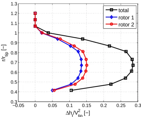
3-5 Specific work done by each rotor and entire CRP for ηad = 82.5 % and ˙ m2/ ˙m1 = 1.1 . . . 57
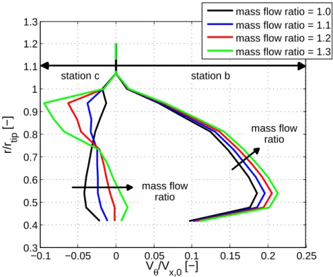
3-6 Influence of mass flow ratio ˙m2/ ˙m1 on tangential velocity downstream of front and rear rotor for ηad = 82.5 % . . . 59
3-7 Baseline CRP design . . . 61
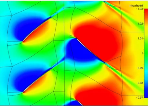
4-1 Baseline CRP density distribution at mid-span . . . 67
4-2 Baseline CRP density distribution at x/D1 = 0.12 . . . 68
4-3 Baseline CRP blade-tip vortex system: front-rotor tip-vortices interact with rear rotor . . . 68
4-4 Baseline CRP entropy distribution near hub (10 % span) . . . 69
4-5 CRP noise estimation methodology . . . 76
4-6 Grid 1: Original baseline CRP grid-block topology . . . 80
4-7 Grid 2: Improved baseline CRP grid-block topology . . . 80
4-8 Grid 2: Close-up of rotor meshes at mid-span . . . 81
4-9 Baseline CRP density distribution at x/D1 = 0.12 for grid 1 (left) and grid 2 (right) . . . 83
4-10 Baseline CRP radial distribution of mass-averaged stagnation pressure for medium and fine grid levels . . . 85
4-11 Surface pressure distribution on the baseline CRP front-rotor blades for medium and fine grid levels . . . 86
4-12 Front-rotor baseline CRP pressure coefficient at two radial stations for medium and fine grid levels . . . 86
4-13 Baseline CRP entropy distribution near hub (10 % span) for CFD computational setup case 1 (left), case 2 (center), and case 3 (right) . 88 4-14 Baseline CRP spectrum at 85◦ polar angle from the inlet centerline . 92 4-15 Baseline CRP spectrum at 113◦ polar angle from the inlet centerline . 92 4-16 Baseline CRP front-rotor harmonic at frequency BP F1 . . . 93
4-17 Baseline CRP rear-rotor harmonic at frequency BP F2 . . . 93
4-18 Baseline CRP interaction tone level at frequency BP F1+ BP F2 . . . 94
4-19 Baseline CRP interaction tone level at frequency 2 · BP F1+ BP F2 . 94 4-20 Baseline CRP interaction tone level at frequency BP F1+ 2 · BP F2 . 95 5-1 Distribution of section lift coefficient on front rotor, M = 0.25 . . . . 99
5-2 Distribution of sectional lift coefficient on rear rotor, M = 0.25 . . . . 99
5-3 Dissection of baseline CRP noise mechanisms for interaction tone BP F1+ BP F2, M = 0.25 . . . 100
5-4 Dissection of baseline CRP noise mechanisms for interaction tone 2 · BP F1+ BP F2, M = 0.25 . . . 100
5-5 Dissection of baseline CRP noise mechanisms for interaction tone BP F1+
2 · BP F2, M = 0.25 . . . 100
5-6 Baseline CRP noise mechanism contributors to first six interaction tones (percentages based on p02 averaged over forward and aft polar arcs), M = 0.25 . . . 102 5-7 Advanced design CRP radial grid topology . . . 105 5-8 Advanced design CRP geometry and near-field density distribution . 106 5-9 Comparison of baseline and advanced design CRP directivity at
inter-action tone frequency BP F1+ BP F2, M = 0.25 . . . 106
5-10 Comparison of baseline and advanced design CRP directivity at inter-action tone frequency 2 · BP F1+ BP F2, M = 0.25 . . . 107
5-11 Comparison of baseline and advanced design CRP directivity at inter-action tone frequency BP F1+ 2 · BP F2, M = 0.25 . . . 107
5-12 Advanced design CRP noise mechanism contributors to first six inter-action tones (percentages based on p02 averaged over forward and aft polar arcs), M = 0.25 . . . 109 5-13 Relative change in mean SPL for advanced design CRP compared to
baseline CRP . . . 110 6-1 Takeoff performance of investigated aircraft configurations: a) altitude,
b) Mach number, and c) thrust lapse . . . 114 6-2 Tone-Corrected Perceived Noise Level at FAR 36 flyover receiver location119 6-3 EPNL breakdown at FAR 36 flyover receiver location . . . 121 6-4 Tone-Corrected Perceived Noise Level at FAR 36 sideline receiver location123 6-5 EPNL breakdown at FAR 36 sideline receiver location . . . 124 B-1 Overview of CRP noise code structure . . . 132
List of Tables
3.1 Overall baseline aircraft characteristics and mission requirements . . . 46
3.2 Datum turbofan engine characteristics at cruise design point compared to CFM56-7B20 characteristics (extracted from [1]) . . . 47
3.3 Datum turbofan aircraft weight breakdown: Component weights com-puted in FLOPS and relative error of calculated results to data pro-vided by the industry partner . . . 49
3.4 Datum turbofan aircraft low speed performance assessment . . . 51
3.5 Total datum turbofan aircraft EPNL in EPNdB . . . 51
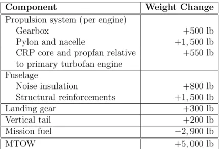
3.6 Weight changes for the baseline CRP powered aircraft relative to the datum turbofan aircraft configuration . . . 54
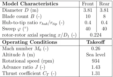
3.7 Model scale baseline CRP characteristics and operating conditions (ex-tracted from [2]) . . . 55
3.8 Model scale baseline CRP cruise performance for ηad = 82.5 % and ˙ m2/ ˙m1 = 1.1 . . . 60
3.9 Computed model scale takeoff performance compared to data from literature [2] . . . 61
3.10 Full scale baseline CRP characteristics and takeoff operating condition details . . . 62
4.1 Characteristics of meshes used in grid convergence study . . . 82
4.2 Characteristics of grid and time step sensitivity study . . . 87
5.2 Model scale advanced CRP configuration and takeoff operating param-eters . . . 104 6.1 Full scale baseline and advanced design CRP configuration and takeoff
operating point characteristics . . . 115 6.2 Total EPNL in EPNdB at FAR 36 flyover location . . . 121 6.3 Total EPNL in EPNdB at FAR 36 sideline location . . . 122 7.1 Change in total EPNL in EPNdB relative to datum turbofan powered
aircraft . . . 126 A.1 Baseline airframe definition - wing and fuselage (in ft) . . . 129 A.2 Baseline airframe definition - horizontal and vertical tail (in ft) . . . . 130
Nomenclature
Abbreviations
CFD Computational Fluid Dynamics CRP Counter-Rotating Propfan
CRPNEC Counter-Rotating Propfan Noise Estimation Code EDET Empirical Drag Estimation Technique
EPNL Effective Perceived Noise Level (EPNdB) ESDU IHS ESDU Engineering Service
FAA Federal Aviation Administration FAR Federal Aviation Regulations
FINE/Turbo Flow INtegrated Environment for Turbomachinery Flows FLOPS Flight Optimization System
GasTurb Gas Turbine Performance Simulation Software HPT High Pressure Turbine
ICAC Initial Cruise Altitude Capability
ICAO International Civil Aviation Organization ISA International Standard Atmosphere LPC Low-Pressure Compressor
LPT Low-Pressure Turbine MFW Maximum Fuel Weight
MEW Manufacturer’s Empty Weight MLW Maximum Landing Weight MTOW Maximum Takeoff Weight
MTOGW Maximum Takeoff Gross Weight MZFW Maximum Zero Fuel Weight
NASA National Aeronautics and Space Administration NLH Non-Linear Harmonic Method
OASPL OverAll Sound Pressure Level OEW Operating Empty Weight
PNLT Tone-Corrected Perceived Noise Level (dB) RANS Reynolds Average Navier-Stokes
RAXAN Rotor AXisymmetric ANalysis ROC Rate of Climb
RVL Rotor Vortex Lattice
SAE Society of Automotive Engineers SFC Specific Fuel Consumption
SL Sea Level
SPL Sound Pressure Level SRP Single-Rotating Propfan
Roman Symbols
A blade area (m2)
A number of angular positions per revolution (-) B blade count (-)
BP F blade passing frequency (Hz) c speed of sound (m/s)
c blade chord (m)
cl sectional lift coefficient (-)
cp specific heat at constant pressure (J/kg)
CD drag coefficient (-)
CP power coefficient (-)
CT thrust coefficient (-)
D diameter (m) f frequency (Hz)
Fi force per unit area on blade surface normalized by ambient pressure (-)
Fi,µ,ν discrete loading element in coordinate direction i, normalized by rtip2 (-)
h altitude (m,ft) h enthalpy (J/kgK) J advance ratio (-)
k loading harmonic order (-) km wavenumber (-)
m, n harmonic of blade passing frequency (-) ˙
m mass flow (kg/s) M Mach number (-)
MN Mach number normal to blade surface (-)
Mtip tip Mach number (-)
N rotational speed (1/s) p static pressure (Pa)
p0 acoustic pressure disturbance (Pa)
pL acoustic pressure disturbance due to dipole sources (Pa)
pt stagnation pressure (Pa)
pT acoustic pressure disturbance due to monopole sources (Pa)
P power (W)
PLm loading noise at harmonic m normalized by ambient pressure (-)
PT m thickness noise at harmonic m normalized by ambient pressure (-)
Q torque (Nm) r radius (m) rhub hub radius (m)
rtip tip radius (m)
SF scaling factor (-)
∆toutput time step at which unsteady pressure data is recorded in CFD simulations (s)
t time (s)
T static temperature (K) T thrust (N)
T time limit for acoustic analogy integrals (s) T period of rotor revolution (s)
Tt stagnation temperature (K)
VN velocity normal to blade surface (m/s)
Vtip rotor tip speed (m/s)
Vx axial velocity (m/s)
Vµ,ν discrete form of thickness source term, normalized by r2tip (-)
Vθ tangential velocity (m/s)
x observer coordinates, x, y, z, normalized by blade tip radius (-) x/D1 rotor-rotor axial spacing (-)
y source coordinates, x0, y0, z0, normalized by blade tip radius (-)
Greek Symbols
β blade angle setting at 75 % span, measured from tangential direction (◦) ηad adiabatic efficiency (-)
ηprop propulsive efficiency (-)
ϕ sweep (◦)
φS tangential source coordinate (rad)
φref blade position reference angle (rad)
φ0 tangential blade element coordinate in source integration (rad)
γ specific heat ratio (-)
π stagnation pressure ratio (-) θ polar directivity angle (◦)
Θ torque split (-) ρ density (kg/m3)
σ phase radius normalized by blade tip radius (-) τ stagnation temperature ratio (-)
ω angular velocity (rad/s) Ψ stage loading (-)
Subscripts
a location upstream of front rotor in baseline CRP design b location between front and rear rotors in baseline CRP design c location downstream of rear rotor in baseline CRP design e exit condition in baseline CRP design control volume analysis cruise cruise operating condition
CRP CRP engine f an turbofan engine F S full scale
LP engine core component on low-pressure spool max maximum quantity
min minimum quantity M S model scale
steady steady quantity
T O takeoff operating condition 0 free stream quantity
1 front rotor 2 rear rotor
µ index for counting source elements in radial direction ν index for counting source elements in chordwise direction
Chapter 1
Introduction
1.1
Background and Previous Work
Advanced open rotor designs have the potential to extend the inherent fuel efficiency benefits of conventional turboprop engines to flight Mach numbers of up to 0.8. By recovering the residual swirl downstream of the front rotor, counter-rotating propfan (CRP) concepts can provide an increase of 6 − 8% in propulsive efficiency compared to single rotor configurations [3] [4]. CRPs have been investigated intensively in the 1970s and 1980s. Two examples of full scale CRPs flight tested in the late 1980s are shown in Figure 1-1. The GE Unducted Fan (UDF) featured two 8-bladed rotors, 11.7 f t in diameter. The PW/HS/Alliston 578-DX had two 11.6 f t diameter 6-bladed rotors. Both model and full scale studies demonstrated significant reductions in fuel burn of up to 30% compared to high bypass engines of 1980 vintage which are currently deployed on most civil aircraft [5].
Currently, propfans are being extensively studied again due to their potential for reduced environmental impact and their inherent noise challenge. However, in the light of future design trends and noise regulations, the aerodynamic and acoustic competitiveness of prospective CRP designs needs to be evaluated relative to perfor-mance levels attained by advanced turbofan configurations. Thus, a credible advanced turbofan needs to be defined to establish a basis for comparison.
air-Figure 1-1: GE UDF flight test on MD-80 in 1988 (left) and PW/HS/Allison 578-DX flight test on MD-80 in 1989 (right)
craft configurations, an integrated noise and performance assessment methodology is required and developed in this thesis. Existing methods are used for aircraft mission and engine cycle analysis, noise prediction of engine core and airframe sources, and for the aerodynamic propfan design and performance assessment. A new approach to estimate CRP noise is developed based on Hanson’s single rotor noise theory [6].
Various approaches have previously been undertaken to predict CRP noise and a summary can be found in [7]. Based on his helicoidal surface theory for propellers [8], Hanson developed one of the first analytical models for CRP noise prediction [9]. In this approach, the sources were placed on the propeller advance surface which made the precise treatment of blade geometric details and non-uniform inflow effects challenging [6].
With the recent advances in numerical methods for aerodynamic and aeroacoustic analyses, hybrid methods based on coupling CFD (Computational Fluid Dynamics) and CAA (Computational Aeroacoustics) have also been pursued [10] [11] [12]. How-ever, CAA methods are expensive in CPU time and memory requirements due to the high mesh densities required to accurately resolve acoustic pressure disturbances. Therefore, carrying out parametric studies in the CRP design phase using coupled CFD/CAA approaches is generally not yet feasible.
Analytical frequency approaches for single rotor [6] and counter-rotating propfan noise [9] require the a priori determination of unsteady blade surface pressures to define the acoustic source terms. In the past, difficulties in obtaining the aerodynamic
data have led to inaccurate noise results [6] but the emergence of CFD now provides the capability to estimate the unsteady blade loading.
In the present work, a new frequency domain approach for CRP noise estimation is developed by extending Hanson’s single rotor noise approach [6] to counter-rotating configurations. In contrast to the helicoidal surface theory, sources are placed on the blade surfaces assuming the source data (surface pressure data and geometry) is available from an external calculation. High-fidelity full-wheel 3-D RANS simulations using the commercially available CFD tool Numeca FINE/Turbo are demonstrated to successfully generate the required surface pressure information. One of the main advantages of the developed CRP noise approach is the low computation time re-quirement allowing the method to be used for detailed parametric studies.
One of the primary concerns in developing a viable CRP engine design is the noise impact of open rotors, in terms of both in-flight cabin noise and takeoff/approach community noise. At cruise, thickness and loading noise are the key noise sources and the rotor-alone tones dominate the CRP spectrum. At the low-speed FAR 36 noise certification conditions during takeoff and approach, rotor-rotor interaction noise due to aerodynamic interference effects tends to dominate the noise signature [13]. The current work focuses on the investigation of CRP interaction tones in order to explore what characteristics and attributes are needed in a CRP design to meet future noise regulations.
It is assumed in this thesis that the mechanisms responsible for the CRP inter-action noise can be attributed to the following unsteady flow features: (1) rear-rotor upstream influence interacting with the front rotor, (2) tip-vortices shed from the front rotor interfering with the rear rotor, (3) front-rotor viscous wakes affecting the rear-rotor loading, and (4) front-rotor hub wake and hub boundary layer influencing the rear-rotor hub loading [14].
Several CRP noise reduction technologies such as variations in rotor-rotor spacing, rotor tip speed, or rotor blade count [15] [16], as well as reductions in rear-rotor diameter [17] and blade wake management [18] [19] have been explored in the past. In general, reductions in interaction tones were observed when the effects of a single
noise reduction technology were investigated. For example, Janardan et al. [15] reported a 10 dB reduction in the summed interaction tone levels at the takeoff condition over a large range of polar emission angles when increasing the rotor-rotor spacing of a model scale CRP with 9 front- and 8 clipped rear-rotor blades by 40 %. However, a detailed experimental or computational evaluation of the effectiveness of the different CRP noise reduction technologies starting with the dissection of the above noise source mechanisms has not been carried out to date. The CRP noise estimation method developed in this thesis is used to quantify the influence of the underlying CRP noise mechanisms on interaction noise. Based on the results, the acoustic benefits of selected CRP noise mitigation concepts are investigated.
1.2
Research Questions
For CRPs to be a viable alternative to advanced high bypass ratio, low fan pressure ratio turbofan engine designs, both their aerodynamic and acoustic performance must be improved. The research described in this thesis is focused on establishing an inte-grated performance and noise assessment methodology for advanced propfan powered aircraft configurations. The methodology is applied to carefully defined CRP aircraft arrangements to answer the following research questions:
1. Since the CRP acoustic signature is tone noise dominated, are open rotors a viable alternative to high bypass ratio turbofans given the stringent noise certification requirements?
2. Based on the insight gained by dissecting and quantifying the relative impor-tance of the source noise mechanisms responsible for CRP interaction noise, what are the characteristics and enabling noise mitigation technologies required to design a quiet propfan propulsion system?
3. Implementing advanced CRP noise reduction concepts, what are the trade-offs between acoustic and aerodynamic performance? What level of noise reduction can be achieved by implementing advanced source noise mitigation concepts?
The goal of this work is to quantify the potential acoustic benefits which can be achieved by implementing CRP noise reduction technologies on a consistent aircraft mission basis relative to advanced turbofan aircraft configurations. The success cri-terion is to demonstrate that CRPs of advanced design can achieve significant noise reductions while maintaining or improving aerodynamic performance.
1.3
Technical Roadmap
The objectives are to dissect and quantify the impact of the aerodynamic mecha-nisms responsible for CRP interaction tone noise and to design an advanced CRP configuration for improved acoustic performance with no penalties in aerodynamic performance. The following conceptual were carried out to answer the research ques-tions stated above.
The first step is to establish an integrated aerodynamic and acoustic performance analysis methodology. The methodology is not limited to CRP powered aircraft con-figurations but is capable of also dealing with turbofan arrangements such that CRP performance results can be compared to advanced turbofan performance levels on a consistent mission basis. The overall performance and noise assessment framework consists of four major modules: mission analysis, propulsion system analysis, low speed performance assessment, and noise estimation.
The second step is to define the concept aircraft configurations. First, given a 3, 500 nm mission, a baseline aircraft configuration powered by a datum high bypass ratio, low fan pressure ratio turbofan was defined and used to validate the methods incorporated in the overall methodology. Next, based on the datum turbofan powered airframe, a baseline CRP arrangement was designed1.
The integration of the CRPs necessitated modifications of the turbofan powered baseline airframe including a rearward shift of main wing and landing gear due to sta-bility constraints and fuselage weight penalties due to structural reinforcements and
1Certification challenges such as blade containment are acknowledged but not taken into account in the present analysis.
cabin noise insulation. The baseline CRP gas turbine cycle was based on the datum turbofan and the CRP was sized to meet the thrust requirement at takeoff/top-of-climb. The development of the baseline CRP geometry was guided by data available in the literature [2] and the detailed aerodynamic design was finalized to match re-ported takeoff performance characteristics using single and dual rotor vortex-lattice methods.
The major challenge in developing the overall aerodynamic and acoustic perfor-mance assessment methodology is the assessment of the noise generated by the prop-fan rotor blades. Coupled CFD/CAA methods are too computationally expensive to carry out parametric studies exploring the benefits of CRP noise reduction tech-nologies thus a first-principles based approach is preferred. Since the accuracy of the proposed frequency domain method is controlled by the accuracy of computing the aerodynamic interaction, a high-fidelity CFD approach is required. To estimate the CRP noise, the third step of the technical roadmap is to establish a frequency do-main approach based on Hanson’s single rotor noise method. The derived CRP noise method was validated by comparing the baseline CRP noise results to measured data available for the same CRP configuration albeit with differences in the exact details of the blade profiles.
In order to accurately capture the aerodynamic interaction between the CRP blade rows and to determine the unsteady blade surface pressures necessary to define the acoustic source terms, the fourth step is to establish a high-fidelity CFD method. To this end, a full-wheel 3-D unsteady RANS approach was implemented. A meshing strategy was developed with the aim on minimizing computational costs. Detailed grid convergence and time step studies were carried out to ensure that underlying CRP flow features (front-rotor tip-vortices and viscous wakes, rear-rotor upstream influence, and hub wake and boundary layer) are adequately resolved.
The CRP noise method derived in this thesis allows to analyze the influence of the noise source mechanisms inherent to CRP applications. In order to determine the required characteristics and define necessary design features of a quiet CRP configu-ration, the noise source mechanisms were dissected and their respective impacts were
quantified for the baseline CRP definition. Based on the results of this noise source investigation, the baseline CRP was re-designed for reduced noise incorporating CRP source noise mitigation concepts. The aerodynamic performance was maintained in the re-design. The resulting advanced design CRP was again assessed for noise and the achieved interaction tone reductions were quantified.
Finally, noise results at the FAR 36 observer locations are presented on the aircraft system level for the baseline CRP and advanced design CRP aircraft configuration. The CRP noise levels were compared to the datum turbofan powered aircraft in order to evaluate the relative acoustic performance and determine what noise levels can be achieved with an advanced open rotor design.
1.4
Thesis Contributions
A multidisciplinary integrated noise and performance assessment capability was es-tablished to evaluate the acoustic and aerodynamic performance of advanced CRP designs on the aircraft/engine system level. A frequency domain method based on extending Hanson’s single rotor noise approach to counter-rotating propfan configu-ration was implemented to assess the CRP noise levels. The approach was coupled with high-fidelity full-wheel 3-D unsteady RANS simulations to capture the underly-ing CRP noise source mechanisms and to determine the time-varyunderly-ing blade surface pressures necessary to define the acoustic source terms. The method is capable of exploring source mitigation concepts and conducting parametric studies
A detailed quantitative assessment of the underlying noise source mechanisms was conducted for a baseline CRP design guided by data available in the literature. The results indicate that although certain interaction tones are dominated by related mechanisms, in order to achieve significant interaction tone noise reductions, all noise source mechanisms need to be addressed. The acoustic performance assessment of a re-designed CRP incorporating advanced source mitigation concepts suggests that it is possible to meet Chapter 4 noise limits with advanced open rotor designs2.
noise levels no greater than the Stage 4 noise limit prescribed in section B36.5 of the FAR 36 noise standards [20].
Chapter 2
Integrated Aircraft Performance
and Noise Assessment
Methodology
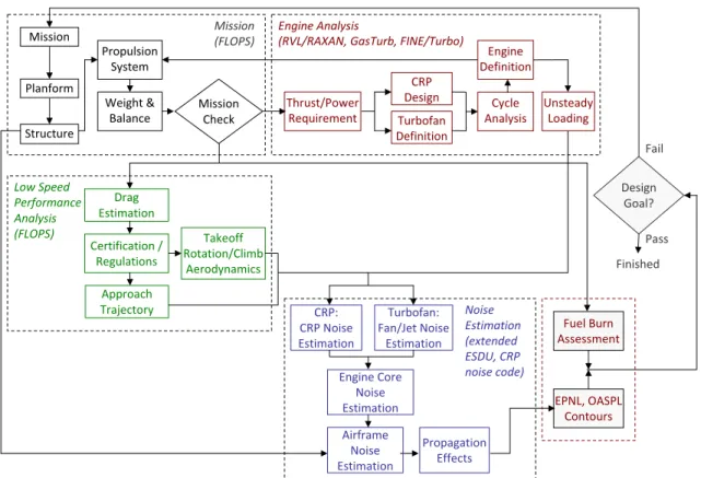
An overview of the integrated aircraft performance and noise assessment framework is depicted in Figure 2-1. The methodology consists of four major modules and is capable of assessing both turbofan and propfan powered aircraft configurations.
The overall framework begins with the mission analysis. After defining the mis-sion to be studied, the aircraft planform and the propulmis-sion system are selected. A weights and balance assessment is performed first. The mission and aircraft data are inputs to the second module of the overall framework, the analysis of the engine. The most important parameters fed into this module are the thrust and power re-quirements at takeoff/top-of-climb, and at the cruise design point. A suitable engine capable of meeting the required thrust values is defined and the engine cycle analysis is performed. The resulting engine definition is passed back to the mission assessment module to obtain updated weights, balance and performance results. This process is iterated until an aircraft/propulsion system is determined which meets the mission requirements. The performance data of the selected aircraft is input to the take-off and approach performance analysis module, the third major part of the overall methodology. The low speed drag polars are computed and takeoff and approach
Framework for Propfan/Aircraft Design & Analysis
Mission Propulsion System Planform Structure Weight & Balance Drag Estimation EPNL, OASPL Contours Low Speed Performance Analysis (FLOPS) Certification / Regulations Approach Trajectory Design Goal? Fail Finished Pass Takeoff Rotation/Climb Aerodynamics Mission Check Mission (FLOPS) Fuel Burn Assessment Engine Definition Thrust/Power Requirement CRP Design Engine Analysis (RVL/RAXAN, GasTurb, FINE/Turbo) Turbofan Definition Cycle Analysis CRP: CRP Noise Estimation Noise Estimation (extended ESDU, CRP noise code) Engine Core Noise Estimation Turbofan: Fan/Jet Noise Estimation Airframe Noise Estimation Propagation Effects Unsteady LoadingFigure 2-1: Integrated aircraft performance and noise assessment methodology for turbofan and propfan configurations
trajectories are obtained following the FAA regulations specified in [21].
The last module of the overall methodology is the aircraft/propulsion system noise estimation. The results of the analyses above are used as inputs: the aircraft structural definition is required for the airframe noise estimation, various engine cycle parameters and the unsteady blade loading in the case of a CRP powered aircraft are needed for the engine noise calculations, and the takeoff and approach trajectories are required to compute propagation effects. Finally, the overall framework provides fuel burn results in terms of SFC and noise results in terms of EPNL and OASPL contours.
The methodology developed in this thesis can be used to quantify the acoustic benefits of advanced CRP noise reduction technologies (e.g. increased rotor-rotor axial spacing, reduced rear rotor diameter, or differential tip speeds) on the prop-fan/aircraft system level. Moreover, the methodology allows to investigate the effects of noise reduction technologies on the aerodynamic performance of CRP powered aircraft. The following sections deal with the details of the aforementioned modules starting with the mission analysis.
2.1
Mission Analysis
In the mission analysis module, the airframe, engine type, and engine/airframe in-tegration parameters are specified. The component weights are calculated and a de-tailed mission performance analysis is performed using NASA’s Flight Optimization Software FLOPS [22]. FLOPS is a multidisciplinary system for the conceptual and preliminary design and evaluation of advanced aircraft concepts and is composed of nine primary modules: weights, aerodynamics, engine cycle analysis, propulsion data scaling and interpolation, mission performance, takeoff and landing, noise footprint, cost analysis, and program control.
The developed methodology depicted in Figure 2-1 primarily uses FLOPS’ weights, aerodynamics, mission performance, and takeoff and landing modules. The engine cycle analysis and noise estimation approaches implemented in FLOPS are dated
1994 and 1981, respectively. The developed methodology is required to be capable of assessing high bypass ratio, low fan pressure ratio turbofan designs. However, the correlations included in the FLOPS methods are not always applicable to advanced turbofan configurations. Therefore, higher-fidelity methods were applied for engine analysis and noise assessment as outlined in Sections 2.2 and 2.4, respectively.
The weights module uses empirical relationships to predict the weight of each item. The input parameters consist of the airframe dimensions. The main wing ge-ometry can be input in more detail in terms of the airfoil characteristics at several spanwise stations. The propulsion system weight is based on the engine thrust rating. The fidelity of the propulsion system weight prediction can be increased by specifying further engine parameters such as nacelle dimensions. In addition, any component weight estimation results from external assessments can be included in the calcula-tions. The FLOPS weight module was validated using a datum turbofan aircraft configuration and the results are presented in Section 3.1.
A modified version of the Empirical Drag Estimation Technique (EDET) [23] is applied for the aerodynamic performance assessment. Modifications include smooth-ing of the drag polars and more representative Reynolds number calculations [22]. The aerodynamic performance calculations in FLOPS were also validated using an advanced turbofan aircraft configuration with the results described in detail in Chap-ter 3.1.
The calculated weight and aerodynamic data are used in the mission analysis module to compute the aircraft mission performance. As outlined in the next section, the required engine data is computed using the cycle analysis tool GasTurb, and vortex-lattice and 3-D RANS calculations in the case of a propfan powered aircraft configurations.
Takeoff, climb, cruise, and descent segments are included in the mission simula-tions. The mission fuel assessment includes calculations of fuel reserves to account for flight to an alternate airport and a specified hold segment as required by the FAA. Iteratively, FLOPS provides performance data for each specified segment including detailed fuel burn results.
2.2
Engine Analysis
For a given mission, the thrust requirements at takeoff/top-of-climb and cruise deter-mined in FLOPS are input into the engine analysis module. The cycle analysis for the specified turbofan or CRP gas generator is performed in GasTurb 11 [24]. Gas-Turb allows to compute the cycle parameters at both design and off-design conditions. The design point cycle analysis is used to evaluate the fuel burn. At off-design condi-tions during takeoff and approach, the cycle analysis provides the engine parameters required for the noise assessment as described in Section 2.4.
In the case of a CRP powered aircraft, the aerodynamic design of the prop-fan is carried out at the low-speed takeoff condition using the single and dual ro-tor vortex-lattice methods, Roro-tor Vortex Lattice (RVL) and Roro-tor AXisymmetric ANalysis (RAXAN) [25] as outlined in Section 3.2. At both takeoff and approach, RVL/RAXAN calculations are performed to iteratively find the optimum operat-ing conditions meetoperat-ing the thrust requirements obtained in FLOPS. In addition, RVL/RAXAN simulations yield the shaft power to be provided by the CRP gas generator.
RVL/RAXAN does not account for compressibility effects and therefore cannot be used at cruise. 3-D steady RANS simulations are required to conduct CRP per-formance studies at cruise. However, in order to optimize the CRP at cruise for propulsive efficiency, parametric studies including tip speed and blade angle setting variations are necessary. Due to data processing and CPU time limitations, detailed parametric studies using 3-D RANS computations are challenging. Thus, the cruise optimization of the CRP configuration could not be performed within the scope of this research but can be carried out in the future.
The focus of the CFD simulations is on noise assessment. In order to determine the time varying blade surface pressures required for the CRP acoustic analysis, full wheel unsteady 3-D RANS simulations of the counter-rotating stage are performed using Numeca FINE/Turbo [26]. The CRP noise assessment and CFD simulations are described in detail in Chapter 4.
As illustrated in Figure 2-1, the engine parameters obtained in the engine cycle analysis are used as inputs to the mission performance assessment in FLOPS. Itera-tively, the engine/aircraft configuration characteristics required to meet the mission constraints are determined.
2.3
Low Speed Performance Analysis
In the low speed performance analysis module, the takeoff and approach trajecto-ries required for the noise audit are computed by combining an external low speed drag polar method with the low speed aerodynamics assessment method included in FLOPS. The low speed drag polar method is needed since FLOPS requires the input of detailed lift and drag coefficient data at takeoff and landing to generate the trajectories. The method implemented in this work was developed by March [27] and calibrated using a combination of Boeing flight test data, NASA wind tunnel re-sults, and an empirically-tuned Lockheed method. The method is generally capable of predicting clean-configuration drag polars with about 1 % error while calculations including deployment of high-lift devices have about 3 % error.
In addition to the takeoff and landing trajectories, the low speed performance module in FLOPS computes the all-engine takeoff field length, the balanced field length including one-engine-out takeoff and aborted takeoff, and the landing field length. Moreover, the approach speed is calculated, and the second segment climb gradient and the missed approach climb gradient are evaluated [22]. It is ensured that all FAR 25 [21] requirements are met. If limited takeoff and landing field lengths are prescribed, the flap and slat deflection angles are iteratively varied in the low speed drag polar method until operating conditions are found such that the field length conditions are satisfied.
Atmospheric Attenuation Ground Reflections Lateral Attenuation SPL(x,y,f,t) EPNL Processing EPNL at FAR 36 Observer Locations Airframe Noise (ESDU):
• Wing • Flaps, LE Slats • Horizontal/Vertical Tail • Landing Gear
Fan Noise (ESDU) Jet Noise (Stone 2) Fan Treatment (GE Method) Airframe (FLOPS) Aircraft Design Engine Core (GasTurb) Propulsion System Design Noise Propagation from Aircraft to Ground
DESIGN NOISE ESTIMATION PROPAGATION (ESDU) 1. Design airframe and
propulsion system
2. Estimate noise emission 3. Propagate noise to
ground 4. FAR36 (EPNL)
Flight Simulation FAR Points and
Trajectory (FLOPS) Turbofan CRP Design (RVL/RAXAN) Blade Loading (FINE/Turbo) LPC Noise (ESDU) Combustor Noise (ESDU)
LPT Noise
CRP Noise Method
Figure 2-2: Noise assessment framework
2.4
Noise Audit
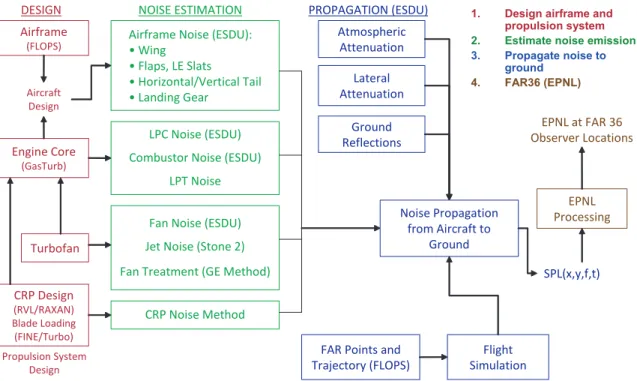
The takeoff and landing trajectories, airframe characteristics, engine cycle data, and unsteady blade surface pressures in the case of a CRP configuration are required for the noise assessment as shown in Figure 2-1. The main thrust of this thesis is focused on the estimation of the noise generated from the CRP rotors and the development of the CRP noise estimation approach is given in detail in Chapter 4. In addition, a combination of existing analytical and empirical methods is used to compute the noise from airframe, engine core sources, and fan in the case of a the acoustic assessment of a turbofan configuration and to account for noise propagation effects to the FAR 36 certification locations.
An overview of the noise assessment module is presented in Figure 2-2. Using data from FLOPS, GasTurb, and FINE/Turbo, the aircraft/propulsion system noise estimation is subdivided into the evaluation of airframe noise, engine core noise, fan and jet noise in the case of a turbofan powered aircraft, and rotor noise in the case of a CRP powered configuration.
All noise calculations are carried out at ISA+10◦C day, 70 % humidity, zero wind, and sea level conditions. The metric used for FAR 36 noise certification is the effective perceived noise level (EPNL) [20]. It is computed from the instantaneous sound pressure level in each of the 24 one-third octave bands for each 0.5 s increment along the aircraft takeoff or landing trajectory. The sound pressure levels are converted into perceived noise levels, based on noy, and corrected for tones and duration of the sound to capture the effective perceived noise, in EPNdB, generated from the aircraft/propulsion system configuration at each of the sideline, flyover, and approach observer locations. In addition to EPNL calculations, which are based on the one-third octave sound pressure levels, the method is capable of computing noise contours in A-weighted overall sound pressure level (OASPL) for a given aircraft position during takeoff or approach. The methods incorporated in the noise assessment module are briefly described below.
2.4.1
Airframe Noise
The noise generated by the airframe is computed with ESDU’s airframe noise mod-ule which uses semi-empirical methods proposed by Fink [28] and Zorumski [29] with modifications to directivity and spectral functions based on recently available data [30]. The method can be used to estimate airframe noise from the following sources: main wing, flaps, leading edge slats, horizontal tail, vertical tail, and nose and main landing gear1. The spectral and directivity characteristics of the these
air-frame sources were derived analytically or empirically, or were assumed similar to sources of known characteristics [30]. Acoustic interaction between the components is not accounted for. Required inputs include span and area data for the main wing, tails, and flaps, as well as flap and slat deflection angles. Number and diameter of nose and main landing gear wheels are needed along with strut lengths to compute the landing gear noise.
1Most of the fluctuating lift and drag forces governing airframe noise are associated with the noise from the wing, tail, and landing gear. The noise contribution from the fuselage is considered negligible, even though the fuselage produces some lift.
2.4.2
Engine Core Noise
The engine core noise estimation is subdivided into noise generated from the low-pressure compressor (LPC), the combustor, and the low-low-pressure turbine (LPT). The noise from high pressure compressor and high pressure turbine is not accounted for, as their contribution is negligible compared to the low-pressure components.
1. LPC Noise
The noise from the LPC is calculated using the fan/compressor noise module in ESDU [31] which is based on Heidmann’s method [32] and is a modified version of the Boeing-Ames procedure given in [33]. The noise radiated from inlet and discharge duct is computed separately, in both cases broadband and tone noise components are accounted for. In addition, multiple-pure-tone noise or “buzz-saw” noise is calculated in the inlet duct when the relative tip speed is supersonic. For multi-stage compressors, the final spectrum is obtained by summing the sound energy from each stage. Blade row attenuation is included in the calculations based on empirical data depending on the number of rotor and stator blades in each stage. The method predicts the spectral shape, level and free-field directivity. Corrections applied to the basic spectrum levels depend on the presence or absence of inlet guide vanes, the rotor-rotor spacing, inlet flow distortions during low speed ground-roll operations, and tone cut-off where the fundamental tone is suppressed according to a criterion determined by the number of rotor and stator blades and the value of the rotor tip Mach number. The main input parameters required for the LPC noise estimation are the mass flow rate, the stagnation temperature rise for each compressor stage, both design and operating point values of the rotor tip relative inlet Mach number, and certain fan geometry data (rotor-stator spacing and number of rotor and stator blades for each blade). The required cycle parameters are computed in the engine analysis module using GasTurb.
2. Combustor Noise
which was developed based on the semi-empirical method described in [35]. The method accounts for noise of the combustion itself, propagating out of the en-gine through the exhaust nozzle, and entropy noise, generated when the hot turbulent products of the combustion process pass through the pressure gradi-ents in the turbine stages downstream of the combustor. The mass flow rate through the engine core, the stagnation pressure and temperature at the com-bustor inlet and exit, and the stagnation temperature drop across the turbine components are needed to assess the combustor noise.
3. LPT Noise
ESDU does not include a turbine noise estimation capability, thus a semi-empirical method developed by Dunn and Peart [33] was implemented as pre-sented in [36]. The input requirements consist of the mass flow rate, the static and stagnation temperatures at the turbine exit, the rotor tip speed, as well as the number of blades and the ratio of stator chord to stator-rotor spacing. Applying this method to the advanced turbofan engine outlined in Section 3.1, however, provided noise levels significantly higher than expected for an advanced LPT design. The discrepancies are suggested to be due to the method not being applicable to more recent turbine designs. In the light of these observations, corrections were applied to the calculated LPT noise based on discussions with the project industry partner.
2.4.3
Turbofan Powered Aircraft: Fan and Jet Noise
For a turbofan powered aircraft, fan and jet noise need to be estimated. 1. Fan Noise
The compressor noise module in ESDU is also applicable to fan blade rows, thus the method described above was used for fan noise assessment with inputs calculated from the cycle analysis. Multiple-pure-tone noise caused by blade-to-blade variations is accounted for in the fan noise method.
aft fan duct are determined using an empirical method developed by Kontos et al. [37]. Input requirements include the treatment length up- and downstream of the fan, as well as the fan inlet radius and the aft fan duct height. The computed attenuation spectra are then applied to the fan sound pressure levels obtained using ESDU’s compressor noise module.
2. Jet Noise
The jet noise module incorporated in the noise audit methodology is capable of dealing with single and coannular exhaust nozzles. A semi-empirical method developed by Stone et al. [38] was implemented. For a dual stream jet, the noise sources contributing to the overall jet noise are attributed to the following mechanisms: (1) inner stream mixing noise (mid to high frequency noise) gen-erated by the shear layer between primary and secondary jet stream, (2) outer stream mixing noise (high frequency) due to small scale mixing near the nozzle exit, and (3) merged mixing noise (lowest frequency) generated by the mixing of coherent large scale turbulent jet structures with the ambient flow downstream of the nozzle exit. In addition, a plug separation noise component (high fre-quency) is present in nozzles with center plugs. The Stone jet noise method includes all of the above noise source mechanisms. The method requires the nozzle flow properties (core and bypass stream nozzle exit velocities, stagnation temperatures, and mass flow rates) computed in GasTurb and the geometric dimensions of the nozzle.
2.4.4
Propfan Powered Aircraft: CRP Noise
In the case of a CRP powered aircraft configuration, counter-rotating propfan noise is computed using the CRP noise estimation method described in Chapter 4. The frequency domain CRP noise method developed here requires the time-varying blade surface pressure data computed using 3-D unsteady RANS simulations. Additional required inputs are the CRP operating conditions during takeoff and approach. The speed off-design data is determined using vortex-lattice methods and the
low-speed performance assessment module in FLOPS as outlined in Chapters 2.2 and 2.3, respectively.
2.4.5
Propagation Effects
The above methods include spherical spreading effects. The sound pressure levels at the observer decrease in intensity with the square of the propagation distance from the source. However, sound pressure levels are further attenuated by atmospheric molecular absorption. Atmospheric absorption varies linearly with distance and the rate of attenuation depends on frequency and varies with ambient temperature, pres-sure, and humidity. The attenuation due to atmospheric absorption is estimated using atmospheric absorption method in ESDU [39]. In addition, the noise received by the observer is influenced by ground reflection effects. Sound waves directly from the source and sound waves reflected off the ground surface are simultaneously received at the observer location. The emitted and reflected waves cause local constructive and destructive interference. Ground reflection effects depend on frequency, the dis-tance of the observer from the reflecting surface, and local ground impedance. The influence of ground reflection on the noise received at the observer is evaluated using the procedures described in [40] and [41].
2.4.6
Post-Processing for FAR 36 Noise Assessment
Using the airframe characteristics, engine cycle parameters, unsteady CRP blade loading, and takeoff and approach trajectories as input data, the noise results from the above sources are post-processed in Matlab and EPNL values are obtained at the FAR 36 observer locations. However, in order to reduce computational cost, only three off-design conditions are simulated to determine the required engine cycle properties for the flyover and sideline observer locations: (1) at Mach 0.1, (2) when the aircraft begins rotation, and (3) at cutback. The engine parameters are then assumed to be approximately constant between two off-design conditions. Similarly, the cycle properties are approximately constant during the final part of the approach trajectory
and the required engine parameters are computed only for the flight condition at 6, 560 ft ahead of the runway which corresponds to the aircraft being directly above the approach observer position.
2.4.7
Summary
In summary, an integrated framework for the aerodynamic and acoustic performance assessment of turbofan and propfan powered aircraft arrangements was established in this chapter. Existing analytical and empirical methods were implemented for the mission analysis, engine cycle assessment, low-speed performance calculations, and the noise prediction of airframe, engine core, and fan sources. Corrections based on trends observed in advanced engine designs were applied to the calculated turbine noise results as the available method is not applicable to advanced turbine configura-tions. The methods described in this chapter are necessary in order to assess aircraft noise at the FAR 36 observer locations and the methods were validated using a given turbofan powered aircraft definition as discussed in the next chapter. The overall focus of this thesis is on the development of a high-fidelity CRP noise estimation approach which is incorporated in the noise framework illustrated in Figure 2-2. The developed CRP noise method is described in detail in Chapter 4.
Chapter 3
Concept Aircraft Definitions
Advanced open rotor designs are regarded as potential propulsion systems mostly for future short- to medium-range narrow-body aircraft. A 737 size twin engine aircraft was defined as a representative baseline configuration. The selected aircraft seats 150 passengers and has a range capability of 3, 500 nm at cruise Mach number 0.78. An advanced high-bypass turbofan engine was chosen as the propulsion system. This datum turbofan aircraft configuration was used to validate the overall methodology and provides a basis for comparison for the CRP powered aircraft arrangements which are the focus of this research. The definition of the datum turbofan/baseline airframe configuration is described in detail in the first part of this chapter.
Powered by two aft fuselage pylon mounted pusher CRPs, a second aircraft based on the airframe of the turbofan powered aicraft and for the same mission was defined next and is denoted as the baseline CRP configuration throughout this thesis. The design of the CRP engine and the modifications to the baseline airframe due to the integration of the CRPs are outlined in the second part of this chapter.
3.1
Datum Turbofan Powered Aircraft
An overview of the mission and baseline airframe definitions is given first. Next, a description of the datum turbofan engine is presented, followed by a summary of the analysis of the datum turbofan aircraft aerodynamic and acoustic performance.
3.1.1
Mission and Airframe Definition
The baseline aircraft characteristics and mission requirements were defined in collab-oration with the project industry partner. The mission specifications are summarized in Table 3.1. Based on the tabulated requirements, a datum turbofan powered aircraft configuration was defined and a detailed performance study and mission analysis was conducted using the tools included in the integrated performance framework shown in Figure 2-1.
Table 3.1: Overall baseline aircraft characteristics and mission requirements
Seating capacity 150
Range capability 3, 500 nm
Design cruise Mach number 0.78
Thrust sizing ICAC 35, 000 ft with 500 ft/min ROC Takeoff field length requirement 6, 500 ft MTOGW/SL/ISA+27 F
The baseline aircraft features two wing mounted advanced turbofan engines with a takeoff static thrust of 24, 000 lb. The primary characteristics of the aircraft include a maximum takeoff weight of M T OW = 152, 400 lb, an overall length of 127 ft, and a span of 113 ft. The geometric dimensions of fuselage, main wing, and tails are presented in detail in Appendix A.
3.1.2
Definition of Datum Turbofan Engine
With future design trends and noise regulations in mind, potential propfan propulsion systems need to be assessed relative to the projected performance levels of advanced turbofans. Therefore, a high bypass ratio, low fan pressure ratio turbofan engine was selected to power the baseline aircraft. The engine is a two-spool unmixed flow configuration and the characteristic parameters are summarized in Table 3.2. The component efficiencies were agreed on in discussions with the industry partner.
In order to verify the calculations performed in GasTurb, cruise design point sim-ulations were carried out for the CFM56-7B20. The CFM56-7B20 is used today pow-ering the Boeing 737-700, which is similar in size to the baseline aircraft and therefore
the generated thrust levels are similar to the selected datum turbofan performance. The computed specific fuel consumption for the datum turbofan of advanced design shows a reduction of 11 % compared to CFM56-7B20 as indicated in Table 3.2. Both the computed datum turbofan and the calculated CFM56-7B20 performance and fuel burn results were carefully checked for consistency with the industry partner.
Table 3.2: Datum turbofan engine characteristics at cruise design point compared to CFM56-7B20 characteristics (extracted from [1])
Datum Turbofan CFM56-7B20
Bypass ratio 8.9 5.5
Fan pressure ratio 1.49 1.65 Overall pressure ratio 36.5 25.6 Turbine inlet temperature 2, 770 R 2, 700 R
Thrust 4, 800 lb 4, 640 lb
Specific fuel consumption 0.536 lb lbh 0.603 lb lbh
As described in Chapter 2, design and off-design computations are performed in GasTurb to determine the fuel burn and the cycle properties required for the noise assessment. These calculations take into account the details of the internal air system including the cooling air mass flows for the high pressure turbine (HPT), the nozzle guide vanes, and the LPT. In addition, the simulations include a pre-defined overboard bleed mass flow.
3.1.3
Datum Turbofan Aircraft Aerodynamic and Acoustic
Performance
The turbofan powered aircraft configuration is sketched on the left in Figure 3-1. It should be noted that the dimensions are not drawn to scale. The results for the weight breakdown, aerodynamic performance, and noise assessment are summarized below.
Figure 3-1: Concept aircraft definitions: Datum turbofan aircraft (left) and baseline CRP aircraft (right) configurations (sketches not to scale)
3.1.4
Weight Breakdown
The component weights computed in FLOPS are compared to the values provided by the industry partner in Table 3.3. It was assumed that 15 % composites are integrated in the wing structure. The fuselage weight was scaled down to 80 % of the value computed by FLOPS to account for composites used in the structural design. The engine weight results computed by FLOPS differed significantly from the data expected for advanced turbofans, mainly due to an unreasonably high thrust reverser weight. Based on the correlation given in [42], the weight of the thrust reversers included in the engine installation group was thus adjusted to 15 % of the primary engine weight. For the major component groups, the weight results computed in FLOPS agree to within 3 % with the data provided by the industry partner. The landing gear weight is the most notable exception. The discrepancies here are due to differences in the weight estimation methods. However, the overall weight data such as MTOW agree to within 2.5 %, thereby verifying the weight prediction module implemented in FLOPS.
Table 3.3: Datum turbofan aircraft weight breakdown: Component weights computed in FLOPS and relative error of calculated results to data provided by the industry partner
Component Computed Relative Error to
Breakdown Weight in lb Industry Data in %
Airframe Structure 37, 900 2.75 Wing 14, 300 0.29 Fuselage 14, 900 −0.15 Tails 3, 100 −12.07 Landing gear 5, 600 33.72 Aircraft Systems 8, 100 1.64 Electronic Systems 2, 700 -4.50 Electronics 2, 200 −1.79 Instruments 500 −15.17 Engine Installation 8, 200 0.16 Primary engine 7, 200 0.42 Wing installation 1, 000 −1.67
Furnishings and Equipment 11, 900 -0.76
Manufacturer’s Empty Weight (MEW) 77, 000 0.54 Operating Empty Weight (OEW) 84, 200 0.51 Maximum Zero Fuel Weight (MZFW)) 123, 800 0.49
Maximum Payload Weight 19, 600 0.45
Maximum Takeoff Weight (MTOW) 155, 500 2.03 Maximum Landing Weight (MLW) 133, 800 2.46
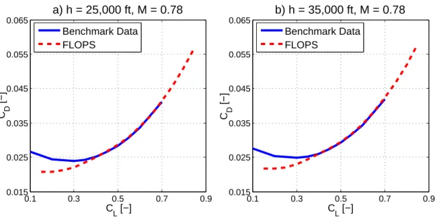
0.1 0.3 0.5 0.7 0.9 0.015 0.025 0.035 0.045 0.055 0.065 CL [−] C D [−] a) h = 25,000 ft, M = 0.78 Benchmark Data FLOPS 0.1 0.3 0.5 0.7 0.9 0.015 0.025 0.035 0.045 0.055 0.065 CL [−] C D [−] b) h = 35,000 ft, M = 0.78 Benchmark Data FLOPS
Figure 3-2: Analysis of the datum turbofan aircraft aerodynamic performance at a) h = 25, 000 ft, M = 0.78 and b) h = 35, 000 ft, M = 0.78
3.1.5
High Speed Aerodynamic Performance
To validate the aerodynamic performance analysis performed in FLOPS, high speed drag polar results were compared to data provided by the industry partner. The drag polars are presented for two flight conditions at cruise Mach number 0.78 in Figure 3-2 a) and b). Good agreement is observed for the lift coefficient range relevant for cruise conditions (0.4 < CL < 0.55). The discrepancies for CL < 0.4 are due to the
drag estimation technique implemented in FLOPS not being applicable to flight at low lift coefficients [23]. Overall, drag polars were compared for altitudes in the range of 1, 000 ft< h < 40, 000 ft and Mach numbers 0.4 < M < 0.8. For all investigated flight conditions the results showed similar behavior to the trends observed in Figure 3-2.
3.1.6
Low Speed Aerodynamic Performance
Using the low speed drag polar method presented in Chapter 2.3, the low speed performance of the datum turbofan aircraft was analyzed. The takeoff and landing field lengths are mostly controlled by the flap and slat settings. The flap and slat
angles were iteratively varied until the mission requirements were met (maximum FAR 25 takeoff and landing field lengths ≤ 6, 500 ft). The final flap and slat settings and the resulting takeoff and landing field lengths for the datum turbofan aircraft configuration are tabulated in Table 3.4.
Table 3.4: Datum turbofan aircraft low speed performance assessment
Takeoff Landing Flap setting 10◦ 35◦ Slat setting 19◦ 35◦ Field length 6, 500 ft 6, 470 ft
3.1.7
Noise Assessment
The overall methodology depicted in Figure 2-1 was executed to obtain the system level noise results for the datum turbofan aircraft configuration. Using the noise estimation methods outlined in Chapter 2.4, EPNL values were calculated at the three FAR 36 observer locations. The results are tabulated in Table 3.5. Compliant with the regulations stated in [20], the sideline EPNL was computed by iteratively varying the axial observer location until the maximum total noise level along the sides of the runway at a distance of 450 m is determined.
Table 3.5: Total datum turbofan aircraft EPNL in EPNdB
FAR 36 Observer Datum Turbofan/ Location Baseline Aircraft
Flyover 87.6
Sideline 89.7
Approach 96.8
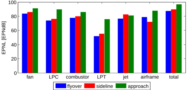
For aircraft powered by high-bypass ratio turbofan engines, the takeoff noise levels are dominated by fan and jet noise, while the fan and airframe sources govern the approach noise [43] [44]. The noise results computed for the datum turbofan aircraft configuration, presented in Figure 3-3, reflect these trends.
fan LPC combustor LPT jet airframe total 0 20 40 60 80 100 EPNL [EPNdB]
flyover sideline approach
Figure 3-3: Total and component acoustic performance of datum turbofan aircraft at FAR 36 observer locations
The total and component EPNL results for the datum turbofan aircraft config-uration were validated using data from an in-house noise assessment at the project industry partner. It was observed that the fan/LPC and fan treatment noise mod-ules used in the developed noise assessment framework tend to overestimate the noise levels from the fan and LPC sources for an advanced turbofan configuration. The fan and fan treatment noise modules are based on correlations derived from experimen-tal data for current turbofan configurations. Computing fan noise from an advanced fan design requires extrapolation of the measurement data potentially leading to sig-nificant inaccuracies. During the validation of the fan noise method carried out by ESDU, the RMS error between measured and one-third octave band sound pressure levels and estimated noise results was up to 5 dB [31].
However, given the overall goal of the present work to compare the noise from advanced CRP powered aircraft configurations on a relative basis, the methods were deemed adequate. More details on the noise results of the turbofan and propfan powered aircraft arrangements are given in Chapter 6.
![Table 3.9: Computed model scale takeoff performance compared to data from litera- litera-ture [2] Calculated Measured (from [2]) C P,T O 2.79 2.78 C T ,T O 1.31 1.19 η prop,T O 67.1 61.1 1](https://thumb-eu.123doks.com/thumbv2/123doknet/14108275.466297/61.918.209.708.177.658/table-computed-takeoff-performance-compared-litera-calculated-measured.webp)