HAL Id: insu-02270109
https://hal-insu.archives-ouvertes.fr/insu-02270109
Submitted on 23 Aug 2019HAL is a multi-disciplinary open access archive for the deposit and dissemination of sci-entific research documents, whether they are pub-lished or not. The documents may come from teaching and research institutions in France or abroad, or from public or private research centers.
L’archive ouverte pluridisciplinaire HAL, est destinée au dépôt et à la diffusion de documents scientifiques de niveau recherche, publiés ou non, émanant des établissements d’enseignement et de recherche français ou étrangers, des laboratoires publics ou privés.
Architecture for Multiprocessor Systems for Distributed
Computing
R Natarajan
To cite this version:
R Natarajan. Architecture for Multiprocessor Systems for Distributed Computing. Embedded Real Time Software and Systems (ERTS2008), Jan 2008, toulouse, France. �insu-02270109�
Architecture for Multiprocessor Systems for Distributed
Computing
R Natarajan, Anurag R
TATA ELXSI LIMITED, Technopark, Trivandrum
Kerala, INDIA-695581
Tel: +91-471-252 7214
Abstract: The growth in technology and the new
developments in the semiconductor domain resulted in the transition of software from an auxiliary role to a primary role in implementing critical systems in vehicles. This resulted in an increasing trend towards the usage of electronic systems in vehicles. The usage of software for precise control and implementation of new features is gaining momentum in both automotive and avionics domain. As a result the number of processing units are fast increasing and systems are becoming more and more complex. The use of distributed computing and the complex requirements demands the need for unique software architecture. The biggest challenge faced by system designers is to have software architecture to maximize the utilization of the computing resources. This paper presents a comprehensive architecture to utilize the power of multi processor systems and high-speed fault tolerant communication protocols, in implementing a distributed computing platform for next generation of systems in avionics and automotive domain.
Keywords: Software architecture, node,
multiprocessing, ”by-wire” system, fault tolerance, redundant system, safety-critical system.
1. Introduction
The usage of electronics in automotive and avionics sector for safety critical systems is growing exponentially. Their use in the critical aspects of driving, braking was restrained by the dependability of the existing communication networks and processing power. The evolution of new communication networks, coupled with powerful semiconductor cores can address the safety critical and fault tolerant electronic system needs The new communication networks (FlexRay, TTP) built up around protocols accommodate powerful techniques to ensure dependability in the data exchange. Also, the usage of multi processor systems is now rapidly increasing to meet the processing power demands. The new features in modern vehicles are accomplished by incorporating feature specific functional modules. This results in the usage of large number of processing centres. As systems become complex, it becomes even more difficult to manage the software development and deployment. The challenge is to develop dependable software architecture for safety critical features for distributed computing. The proposed architecture addresses
multiprocessor computing framework and mechanisms for fault tolerance. The architecture is made configurable and scalable to address multi cores/ multi processors in a single board collaborating on a communication network (distributed computing nodes) The suggested architecture for distributed processing enable the OEMs and Tier-1 manufacturers to develop and deploy several features in the vehicles with considerably less effort in a cost-effective manner with high degree of fault tolerance.
2. Architecture
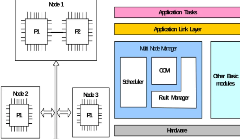
The proposed Multi Node Software Framework is presented in the figure 1 given below. The Multi Node Manager (MNM) manages the hardware resources, and provides set of interfaces that can be employed in developing application tasks. The MNM has two major functionalities: 1. To provide an environment for application task execution 2.For communicating between different nodes in a network.
Node 1
P1 P2
Multi Node Manager
Hardware Scheduler
Fault Manager
Other Basic modules Application Link Layer
Application Tasks COM Node 3 P1 Node 2 P1
Figure 1: Multi Node Software Framework
Definitions:
Node: Any processing unit that forms part of a
distributed system. The node may contain single or multiple processors. In case of multiple processors, the processors can be linked with each other by a link-port. Node can be imagined as a single entity with one or more processors, which does a specific functionality and communicate with similar nodes using a communication port.
Link-port: An interconnection between two or more
processors within a node (local). It can be high-speed link bus or a shared memory.
Communication-port: The communication port
enables a node to be connected with other nodes (Remote) (e.g. TTP, CAN or similar bus architectures).
Messages: Message is any piece of information
exchanged between processing units within a node or between nodes. There are two classes of messages namely System messages and Data messages. The System messages are OS control information & OS data, exchanged between processing units within a node (Local) or between nodes (Remote). The Data messages are information data that are passed locally or remotely
2.1 System Features:
The main features of the proposed MNM task execution module are: support of multitasking fixed number of tasks, pre-emptive task scheduling by static priority, inter-task/processor communication and synchronization via semaphores, messages, and queues. The application tasks can utilize MNM services using the library interface provided. The MNM implements kernel threads for managing the system. These threads communicate with each other using system messages. The main functionalities of the MNM threads are listed below
• Task scheduling
• Command execution
• Communication
• Fault detection and Handling
• Resource management
The services provided by the MNM are of two types: local services and remote services.
An application task can generate a call to a function of the kernel, e.g., to manipulate a semaphore or any other resource, which can be either a Local call, which is executed at the local processor or a Remote call, which is executed in another processor. Calls are either local or remote depending on the location of the resources being manipulated in the call.
The application task execution environment is implemented by scheduler, which supports both Single Processor and Multi processor task execution. In Single Processor configuration the MNM scheduler behaves more or less similar to a commercial RTOS. But in Multi Processor configuration it enables multi processing between different processors in a node interconnected by link -port. The OS resources for multi processing are shared between the different processors using the supported link mechanism. The link ports provide high-speed and bi-directional data transfer between
system nodes. Processing units within a node communicate asynchronously through a link. Links can be used to form a network of processing units. Each processing unit in a node has an identifier, which makes it possible for other components to uniquely identify particular processing unit/node in the system. The processing units communicate through the exchange of messages. Each message can be characterized by a Source & destination id, message priority and data/command. Processing units maintain a static routing table for routing of messages.
The second major functionality is to provide an infrastructure for data exchange between different nodes in a communication network. The communication network can be Time triggered or Event triggered network that helps in information exchange. The data messages are transferred using the above mechanism.
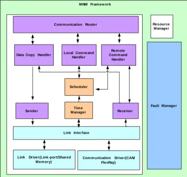
The following sections present the main components of the proposed MNM.
MNM Fram ew ork
Link Driver(Link-port/Shared Mem ory)
Com m unication Driver(CAN/ FlexRay) Link Interface Sender Receiver Scheduler Fault Manager Rem ote Com m and Handler Local Com m and
Handler Com m unication Router
Data Copy Handler
Tim e Manager
Resource Manager
Figure 2: Multi Node Management Modules
2.1 Scheduler
Each application task has a corresponding Task Control Block (TCB), which is a data structure where the task information is stored. A TCB contain the task identification, task priority, the context, task state, and handles of resource object used by the task. All kernel threads can access the TCBs, but they are used mainly for multitasking.
The proposed system use pre-emptive task scheduling based on static priority as scheduling
policy. The kernel uses two parameters to perform multi tasking: the running task and the next task ready to execute.
When a task is running, the two parameters indicate the same task. If an operation that causes the suspension of the running task happens, the thread that executes this operation invokes the Scheduler thread in order to schedule the next task. Another way could be to raise the priority of the next task than the running task in which case the Scheduler thread schedules this task.
Scheduler thread when called saves the machine context in the TCB of the task being suspended and restores the status of the task being scheduled for execution.
2.2 Communication Router
The communication router module manages three threads
• Local Command Handler (LCH) • Remote Command Handler (RCH) • Data copy Handler
Calls generated by the application tasks can be either a local call, which is executed at the local processor or a remote call, which is executed in another processor (node). The decision of remote or local call is determined by the location of the resources being manipulated in the call. When the local processor encounters a remote call, the call is encapsulated in a command message, and this message is sent to the destination processor. At the destination node, the kernel of this processor decodes the command and executes the corresponding call. Some calls return information to the application tasks that generate them. The application task that executes the call is blocked waiting for the call to return.
2.2.1 Local Command Handler
The Local Command Handler thread handles the execution of the local calls. After a call is issued, LCH decodes and executes the call. The execution of a call may trigger the scheduling of another task. In this case, LCH requests the Scheduler thread to schedule this new task for execution.
2.2.2 Remote Control Handler
The Remote Command Handler thread handles the execution of calls received from other processors. RCH is similar to LCH, except for that LCH only receives one call at a time, while RCH can receive multiple calls.
2.2.3 Data Copy Handler
The Copy handler copies data blocks from the processor memory to external node using the sender thread services. After receiving a copy request, Copy handler provides the required data transfer by copying data blocks from the system memory and
forwarding these blocks to the Sender thread. When the transfer finishes, Copy handler sets the task waiting for the copy to be completed as ready to execute. This task may be either a local or a remote task.
The copy handler also manages the data messages transmission and reception to the other nodes. In case of data messages the copy handler sends the message to the corresponding node using the link interface & communication driver services. The received data messages from other nodes are transferred to the task(s) configured for reception.
2.3 Link Interface
Link interface provides a standard interface for the kernel threads to communicate with other processors and nodes within the system. The proposed system uses link ports for inter processor communication. The communication ports are used for the data message exchange between nodes. The link interface also implements a suitable routing algorithm.
2.4. Sender & Receiver
The Sender and Receiver threads handle the sending and receiving of messages through processor link ports and node communication ports. Sender follows a store and forward policy: After receiving a remote request from another thread it sends the message to the link interface. Incoming messages are transferred by the link interface to the receiver thread. After receiving a message, Receiver checks the message destination. In case the destination is the local processor, either a data message copied to the destination address, or a command message is forwarded to RCH, depending on whether data or command messages are received. In case the destination is a remote processor, Receiver requests the appropriate Sender thread to forward the message to the destination. Each message gets the same priority as the application task that generates the message. The messages with higher priorities are sent before (overtake) messages with lower priorities. In case of data messages the sender module transmits the data using the communication driver. The received data messages are transferred to the data copy handler for forwarding to the configured application tasks.
2.5 Time Manager
The time manager monitors the passage of time and manages the timers. This thread handles the system tick used for scheduling. Timers are kept in a timing linked list. When a timeout occurs, i.e., the number of pending ticks for a certain timer equals zero, the timer is removed from the list, the task associated with the timer gets an indication of the occurrence of the timeout, and Scheduler is called in order to schedule the task for execution.
The time manager can also be configured to synchronize all the timing parameters with respect to the network time. This is essential in TTP communication where tasks are configured based on the network time. The scheduler using the schedule tables manages the execution of the tasks. The time manager provides the network time for the schedule management.
2.6 Resource Manager
This module manages all the kernel objects used by the kernel threads, this include semaphore objects, TCBs, memory pools etc.
The capabilities provided by the proposed MNM OS module allow the application tasks to create and manipulate structures such as tasks, semaphores, queues, messages, and timers.
2.7 Fault Manager
The fault manager is responsible for fault detection and management. In case of fail safe system the fault manager triggers the execution of the fail-safe algorithm and manages the system states. In fail-operational configuration, this module is responsible for the faulty node detection algorithm and fault recovery mechanism.
3. Realization of the concept from automotive perspective
The concept was practically realized by building an automotive by-wire system. The system was realized using FlexRay communication protocol as communication backbone. The system was first designed using six nodes, two master nodes (Master and Redundant slave) and four actuator nodes. The
Freescale S12X processor® was selected for this.
The Freescale MFR 4300 FlexRay controller® was
used as the communication interface.
The multi processing features was addressed using Tiger SHARC processors from Analog Devices. Two processors were linked using the LVDS link to form a two-processor node. One Tiger SHARC processor was interfaced with MFR 4300 controller (memory-mapped) for communication interface.
The following sections describe the system that was used to prove the proposed MNM architecture.
3.1 By-wire Systems
A “by-wire” system refers to a control system that designed to replace the traditional mechanical or hydraulic linkages with electronic linkages. This by-wire concept was originally adopted in the aerospace industry. But now by-wire technology has made its entry into the ground vehicles as well. Automotive by-wire includes three categories: throttle by-wire, steer by-wire (SBW), and brake by-wire (BBW). Consider a simple BBW system in a car. This consists of two brake pedal sensors and four brake- actuator nodes at the four wheels.
The Right-Front (R FRONT) and the Left-Rear (L REAR) actuator nodes accept the brake pedal pressure from one fail-silent brake pedal sensor. The Left-Front (L FRONT) and Right-Rear (R REAR) actuator nodes accept the brake pedal pressure from the other fail-silent brake pedal sensor.
R FRONT L FRONT
R REAR L REAR
Figure 3:Brake by-wire system
Every wheel node informs all other nodes about its view of the brake pedal sensors, performs a distributed algorithm to allocate the brake force to each wheel and controls the brake at its local wheel.
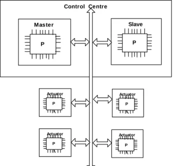
3.2 Brake by-wire system using MNM architecture
The system shown in Figure 3 was realized using the MNM architecture with focus on a centralized control centre with redundancy. This is represented in Figure 4. Control Centre Actuator (FL) P Master P Slave P Actuator (RL) P Actuator (FR) P Actuator (RR) P
Figure 4: Brake by wire (Control Centre and Actuator nodes)
The control centre had two nodes with single processor each, which implements the braking control algorithms. One node in control centre acted
as the master and the other node as the slave. The master and the slave control centres are connected to four simulated actuator nodes on a fault-tolerant communication network like FlexRay.
Both the nodes in the control centre process the data acquired from the different actuator nodes through the communication network. The control actions to be taken are sent through the communication network, which are in turn used by the simulated actuator nodes.
The actuator nodes are configured to accept commands from only one node of the control centre and the commands from the other node are ignored. This makes use of adequate fault-tolerant redundancy mechanisms. Hence each node in the control centre will be a mirror of each other and keep a check on the other one in order to ensure the fault-tolerance of the system.
3.2.1 Task Scheduler and Time Manager
The MNM scheduler was configured in a time triggered way with schedule tables to execute the feature tasks (braking force calculation, vehicle slip calculation and vehicle velocity calculation).
3.2.2 Communication Interface
FlexRay communication was used for network over which the messages are passed. The interface configures the bus for the wake-up, start-up and actives modes of operation. The two nodes of the control centre are configured as coldstart nodes.
3.2.3 Sender and Receiver
The Sender and Receiver handle two types of messages: data messages from the actuator nodes (for brake force information) and data messages to the actuator nodes containing control action information.
3.2.4 Communication Router
System messages are local and are handled by the LCH. The data messages are routed based on the whether it was internal message (vehicle velocity input for slip calculation task) or remote message (brake force for each actuator nodes).
3.2.5 Fault Manager
The control algorithm residing inside the control centre computes the required control force and commands the actuator nodes for actuation In case of a failure of one of the actuator nodes, the algorithm executes the intended function by redistributing the braking forces to the remaining functional actuators. The fault management module of the MNM can detect the fault from the fact that there is no braking force available at one of the actuators and can trigger the execution of the algorithm for the corrective procedure that is to be undertaken.
The fault management module compares the states of the replicated control centre nodes Master and
Slave. If the master fails, it is discarded and the Slave takes its place. The system employed for this node only focussed on the fail-safe behaviour. In order to provide enhanced fault tolerance, TMR may be adopted for the Control centre. The faulty unit could be recognized by the majority voting which would be removed from the system.
3.3 Multi processing using MNM architecture
The multi processing capability of the MNM architecture was also studied for the brake by-wire application.
The control centre had only one node with two processing units interconnected using LVDS link-port processor, which implements the braking control algorithms. One processing unit of control centre node is connected to four simulated actuator nodes on FlexRay network. This node processes the data acquired from the different actuator nodes through the communication network and executed vehicle slip calculation and vehicle velocity calculation tasks. The other processing unit was assigned with the braking force calculation.
In this configuration MNM was handling both local and remote data and system messages. The system message was internal as well as external, since it is a multi processor realization of the control node. The MNM scheduler was configured in a time triggered way with schedule tables to execute the feature tasks in both the processing units of the node
The system messages are of local and remote type. The system messages were employed for synchronization of the tasks running on both the processing units as well as for passing the required data between the processing units. The braking force information was passed to the processing unit with FlexRay interface using system message and the same is transmitted to the actuator nodes as data messages.
The fault handling feature in this system was examined by simulating a failure in one of the brake actuators. Simulation of right front brake actuator failure results in no braking force at the right front wheel. So application of brake results in reduction of total braking force and the total deceleration below the desired values. The proper correction in the algorithm for the redistribution of braking forces was observed.
The system was studied using this configuration to analyse the MNM multi-processing configuration. Using the LVDS link the two processing units performed as expected.
4. Realization of the concept from avionics perspective
Fly-by-wire has been a byword in the avionics field for a considerable period now. We attempt to show
the architecture of a distributed system that implements a Flight Control System for an aircraft. The system was conceived and implemented with dual redundancy, and in hot standby mode, for the safety critical nodes. Triple modular redundancy was also employed in the areas of inertial sensor data acquisition.
The major nodes in the system are the sensor nodes (like the Inertial Navigation unit and the Air Data system), the Flight Control Computer (FCC) for guidance and autopilot, the Actuator Control nodes. In addition the Display Controller node handles the Head Up Display system.
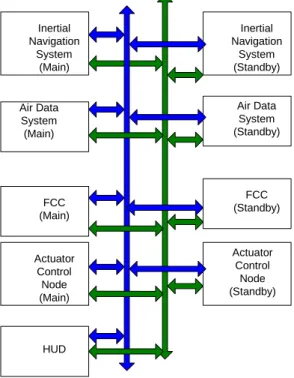
Figure 5 shows the architecture of the Fly-by-wire system for flight control. Each node in this system employed two processors, one of these handling the link port and the other the number crunching and processing. The MIL-STD-1553B bus was used as the link between the various nodes. The deterministic nature of this time division multiplexed bus supports the hard real-time requirements of the system.
Dual redundancy was achieved by duplicating the nodes, viz., by having two chains of operational nodes. Full node connectivity was provided in each chain and between chains cross-connectivity was provided.
In the system, tasks run with static fixed priorities, and follow definite periodicities. Each node was allotted a set of functions that it must execute within a deadline. Also, there exists a precedence relationship between tasks executed in the different nodes. A good example is that sensor data acquisition would need to precede the navigation task. Inertial Navigation System (Main) Inertial Navigation System (Standby) Air Data System (Standby) Air Data System (Main) FCC (Main) FCC (Standby) Actuator Control Node (Main) Actuator Control Node (Standby) HUD
Figure 5. Fly by wire Flight Control System
Communication between the nodes via the 1553B bus also used a time-driven mechanism. The protocol itself supports destination id, data/command messages, as well as a parity check.
Message integrity was enhanced by providing an application software layer over the protocol. This layer uses several message validation mechanisms like CRC checks, parity checks etc. for establishing fault free communication.
4.1 MNM support for fly-by-wire 4.1.1 Scheduler & Time Manager
The scheduler in each node maintains its Task Control Block (TCB) and the Time Manager triggers the execution of each task. For instance, the sensor Acquisition Node acquires information from the sensors, runs sensor-specific compensation algorithms and executes a voting algorithm for sensor data validation before communicating to the Flight Computer. In addition as low-priority task, the node also executed a periodic health check task. The MNM scheduler in these nodes checks that deadlines have been met, and when violated raises appropriate flags. Both local and remote messages are used in these nodes.
Some nodes may operate solely on messages passed to them by the FCC. The MNM scheduler in such cases was event driven rather than time triggered.
In order to support real-time execution of functions in the distributed architecture, tight synchronism among the various nodes was required. The Time Manager executes this function. Real time in each of the nodes is maintained by its own clock. To maintain synchronism among them special system messages are passed over the link ports and the relative skews among the nodes was brought down to the required levels by applying time correction.
4.1.2 Communication Interface
The system uses the MIL-STD-1553B bus for data and system message exchanges. Each node was configured to handle several types of messages corresponding to its functionality. They include the protocol defined BC-RT, RT-BC, RT-RT messages. In addition it also implemented the routing over the appropriate bus. For example, in the FCC it takes the form of accepting inputs from the sensor nodes in the two chains and of communicating control data to the actuator nodes.
4.1.3 Sender and Receiver
The Sender thread in the node, formats and stores the various messages. On receiving a request from another thread, say, the communication task in the TCB, it sends the message to the link interface. The Receiver thread receives messages from the link
interface and routes it to the LCH for an internal command or to the RCH for an external command. For example, the sender in the FCC formats messages to all other nodes for system as well as data messages. Its MNM Receiver routes mostly to the LCH, however in some cases where data needs to be sent between two other nodes, then it would be routed to the RCH.
4.1.2 Communication Router
As explained in the earlier section, the FCC executes calls to both the RCH and the LCH. Several nodes in this system execute calls to the LCH only. Examples are the HUD and the actuator nodes, wherein the message is received from the FCC.
4.2 Fault manager and redundancy management
The distributed, dual redundant architecture was provided with enough connectivity to ensure that the overall function is executed even if one or several of the nodes develops a failure. To elaborate on this, two nodes are employed for carrying out the functions of the Air Data system: viz., calculating parameters like altitude, altitude rates, airspeed, etc using data from the air-pressure sensors. The information from these nodes is sent to both the Flight Control nodes as inputs. Even if one of the Air Data systems were to fail, connectivity is such that both the FCCs would still be provided with valid data. This kind of architecture ensures that the system meets the high reliability figures demanded.
The fault manager in the node has the task of identifying any system faults and containing them as far as possible. Several software schemes like maintaining recovery blocks, or multiple data copies are resorted to for fault containment. If successful, these ensure that the system functions in its primary mode, thereby guaranteeing full function execution. If the fault is such that this is not possible, then the fault manager indicates its fault to the other nodes. In this case, the overall MNM architecture is organised to re-configure the system so that full function is executed as far as possible.
In the event that this is also not possible, the MNM then resorts to falling back to a salvage mode of operation wherein the node supports enough functionality for a safe operation.
The overall architecture thus supported a tightly synchronised fault tolerant distributed system and was highly flexible, amenable to any kind of avionics system.
The MNM architecture also supported a hierarchical tree structure for the communication link, making it possible to include other systems like display and recording systems.
Validation of such a distributed system was a challenging task, but the MNM architecture enables
the software architecture to be validated easily. The main reason for this is that the software components across nodes are common.
5. Advantages of the architecture
MNM is a comprehensive architecture to utilize the power of multi processor systems and high-speed fault tolerant communication protocols, in implementing a distributed computing platform for next generation of vehicles. MNM can cater to the requirements of distributed computing. Multi processing nodes with high processing power can reduce the number of computing nodes. With the computational power of multi processor systems the number existing nodes can be drastically reduced. This can be achieved by developing fewer computational nodes (High load centres), which are connected to the actuator/sensor nodes (Low load centres) through a high-speed communication network. This concept simplifies the testing and diagnostics requirements by virtue of its distributed nature. Providing hardware redundancy can be treated merely as an extension to the distributed architecture, which in turn improves reliability. The other important features of this concept are composability and extensibility. Addition of a node to provide a new feature or to implement a new algorithm is achieved in a cost effective manner and with less effort. These features are attractive both in the avionics as well as the automotive space.
This concept improves the verification and validation procedures, by allowing more standardized procedures, effectively reducing the development cycle time.
Actuator/sensor nodes need only ECUs of lesser computational capabilities. Hence the attempt to employ redundancy at the input/output ends becomes very much cost effective.
Also, having both processor and sensor capabilities on the same chip would result in greater expense. The centralized approach can lead to the scenario where sensors and actuators are separated from the controllers processing the algorithms. This in turn will increase the yield of the discrete sensor and actuator ICs. This brings about reasonable advantages from the chip design and fabrication point as well.
As the number of computing nodes increases, the effort required for software configuration management increases significantly. From the software configuration management perspective reduction in the number of computing nodes makes it easier to maintain the integrity of the system. In distributed architecture certain nodes will be not utilizing the system resources to full extent. The MNM can be used to design a centralized computing scheme to utilize the full capabilities of the computing platform. This concept also reduces the amount of redundant code that goes into system.
All computing nodes make use of basic software layer (MNM and drivers), which is functionally common for all. The basic software component can be a licensed software component that comes from a vendor. Reducing the number of nodes can reduce the license fee for these basic software components that make a node.
Another advantage of this concept is the reduction in bus communication, since the implementations of the different sub-systems are in the same computational centre. The signals required for these sub-systems can be implemented as local data messages. The local data messages can improve the deterministic nature of the system, which is an important characteristic of active safety systems.
6. Limitations
It is challenging to convince the users the applications of proposed framework. Carmakers will have to find ways to make the users feel that such systems are equally desirable. Multi processing techniques and communication protocol like FlexRay is yet to be qualified in extreme environment conditions.
The suggested architecture is not drawn in line with any existing standards. In automotive domain emerging framework like AUTOSAR address distributed computing and the required software infra structure to implement this. But AUTOSAR currently does not address multi processing and safety features. The proposed architecture can be used to complement such standards to address symmetric multiprocessing and safety features.
7. Conclusion
The discussed architecture can address processing using multiple processors to multi tasking using a single processor. The architecture also takes into account the requirements of connectivity, which is vital for distributed computing from a vehicle perspective. Currently the multi processing is envisaged using high-speed link-ports and shared memory, but in future the communication network protocol can support high data rates. This enables the usage of such networks for multi processing thus avoiding current high-speed processor link mechanisms. The MNM architecture is designed in a way to address this, since it is independent of the underlying physical connection scheme employed for multi processing.
The volume of software that goes into a vehicle is enormous. Hence the software that goes into the system will determine the major share of the vehicle cost. The MNM architecture is a unique framework that can address multi processing control centres with low computational power actuator/sensor interconnected using a standard bus communication protocol. This approach as discussed can reduce the
software components that go into the vehicle when compared with pure distributed computing. This will avoid duplicating the same software components in different nodes. This could reduce the total software license costs too. Hence this paper presents a novel approach for cost-effectiveness in automotive and avionics domain in future.
6. Acknowledgement
This work is supported by TATA ELXSI IP development programme. The authors would like to thank the management for supporting their work and for stimulating discussions.
8. References
[1] E.A.Bretz, “By-wire cars turn the corner”, IEEE Spectrum magazine, vol.38, no.4, Apr. 2001, pp. 60-73.
[2] M.Bertoluzzo, P.Bolognesi, O.Bruno, G.Buja, A.Landi, and A.Zuccollo, “Drive-by-wire systems for ground vehicles”, in Proc. of IEEE International Symposium on Industrial Electronics, pp.711-716, 2004.
[3] Tata Elxsi knowledge database
[4] B.Hedenetz and R. Belschner, “Brake-by-wire without Mechanical Backup by Using a TTP-Communication Network”, SAE International Congress
[5] FlexRay Protocol Specification version 2.1 9. Glossary
BBW. Brake By Wire BC Bus Controller
CAN. Controller Area Network ECU. Electronic Control Unit FCC Flight Control computer LCH. Local Command Handler LVDS. Low Voltage Differential Signal MNM. Multi Node Manager
OEM. Original Equipments Manufacturer
OS. Operating System
RCH. Remote Command Handler RT Remote Terminal
RTOS. Real Time Operating System SBW. Steer By Wire
SMP. Symmetric Multi Processing TCB. Task Control Block
TMR. Triple Modular Redundant