HAL Id: hal-01176591
https://hal.sorbonne-universite.fr/hal-01176591
Submitted on 15 Jul 2015HAL is a multi-disciplinary open access archive for the deposit and dissemination of sci-entific research documents, whether they are pub-lished or not. The documents may come from teaching and research institutions in France or abroad, or from public or private research centers.
L’archive ouverte pluridisciplinaire HAL, est destinée au dépôt et à la diffusion de documents scientifiques de niveau recherche, publiés ou non, émanant des établissements d’enseignement et de recherche français ou étrangers, des laboratoires publics ou privés.
predict the fracture behaviour of layered ceramics
designed with internal compressive stresses
Dominique Leguillon, E Martin, O Ševeček, R Bermejo
To cite this version:
Dominique Leguillon, E Martin, O Ševeček, R Bermejo. Application of the coupled stress-energy criterion to predict the fracture behaviour of layered ceramics designed with internal com-pressive stresses. European Journal of Mechanics - A/Solids, Elsevier, 2015, 54, pp.94-104. �10.1016/j.euromechsol.2015.06.008�. �hal-01176591�
Application of the coupled stress-energy criterion to predict the fracture
behavior of layered ceramics designed with internal compressive stresses
D. Leguillon
a*, E. Martin
b, O. Ševeček
c, R. Bermejo
da Institut Jean le Rond d'Alembert, CNRS UMR 7190, Sorbonne Universités, UPMC
Université Paris 06, F-75005 Paris, France.
b Laboratoire des Composites Thermo-Structuraux, CNRS UMR 5801, Université de
Bordeaux, F-33600 Pessac, France.
c Institute of Solid Mechanics, Mechatronics and Biomechanics, Faculty of Mechanical
Engineering, Brno University of Technology, 616 69 Brno, Czech Republic.
d Institut für Struktur und Funktionskeramik, Montanuniversität Leoben, A-8700 Leoben,
Austria.
* Corresponding author dominique.leguillon@upmc.fr
Keywords:
Layered ceramics, coupled stress-energy criterion, residual stresses, crack initiation.
Abstract:
One novel approach to improve the apparent toughness of ceramics is to design a multilayer architecture with embedded layers having compressive residual stresses. Surface cracks propagating during mechanical loading can be deflected within the compressive layers, in order to delay the final fracture of the whole structure. The design of high toughness laminates requires understanding the effect of residual stresses on the initiation and propagation of cracks in the material.
In this work, a coupled stress-energy criterion is used to predict the initiation and propagation of surface cracks in ceramic laminates upon thermo-mechanical loading. Experiments were conducted on V-notched alumina-based laminates to show the effect of residual stresses and mechanical loading on their fracture behavior. The conditions for crack initiation as predicted for notched specimens agreed with the experimental observations. It is shown that the onset of cracks from V-notches is associated with (i) the tensile residual stresses in the first surface layer and (ii) the depth of the notch. The further propagation of the crack into the first embedded compressive layer was also studied. Based upon the coupled criterion, a short penetration of the propagating crack into the first compressive is foreseen. If the mechanical load is increased, the crack finally deflects within the compressive layer propagating with a certain angle which is also predicted with a good accuracy.
1. Introduction
A limitation for the use of ceramics is their low fracture toughness, which often causes spontaneous brittle failure of the component or system. Contrary to metals, crack propagation in brittle materials such as ceramics is usually catastrophic, due to the lack of plastic deformation. The brittle fracture of ceramics is a consequence of the material defects located either within the bulk or especially at the surface, resulting from the processing and/or machining procedures (Morrell, 1999; Danzer, 2002). Under external applied stress, the stress
concentration associated with such defects is the driving force for crack propagation, causing the failure of ceramic components.
Increasing strength in ceramics can be attained by reducing the size of these critical defects (e.g. through colloidal processing) (Lange, 1989), and introducing compressive residual stresses at the surface (e.g. strengthening in glass such as Gorilla glass (Corning, 2012)). However, significant reduction of strength variability cannot be achieved with these approaches. In recent years, a “flaw-tolerant” approach has emerged for building tougher ceramics in a “bio-inspired” layered architecture, combining materials with different microstructures, or properties similar to those found in nature (Launey and Ritchie, 2009). Composite materials using such symmetric multilayer architectures (e.g. ceramic composites such as alumina-zirconia and mullite-alumina among others) have been reported to exhibit increased fracture toughness, higher energy absorption capability and/or non-catastrophic fracture behaviour in comparison to their constituent (monolithic) materials. Among the various laminate designs reported in the literature, two main approaches regarding the fracture energy of the layer interfaces must be highlighted, i.e. the use of “weak” or “strong” interfaces. A particular case of the latter is based on the capability of inducing residual stresses in the layers during cooling from sintering, in order to provide a barrier to crack propagation and, in some cases, even stop cracks (Rao and Lange, 2002).Then, understanding crack propagation in layered ceramic is necessary to optimize their mechanical behaviour. A key feature is the contribution of the residual stresses to the fracture toughness of the individual layers.
The experimental evaluation of the crack growth resistance in brittle materials is often performed on single edge notched (or V-notched) specimens loaded under bending, so called SENB or SEVNB test (Damani et al., 1996). This requires the introduction of a crack (or sharp notch), which is in many cases a challenge in brittle materials. The fracture criterion of brittle materials is usually described by linear elastic fracture mechanics (LEFM), based on the Griffith/Irwin law (Griffith, 1921; Irwin, 1962) but is ineffective in predicting the initiation of a new crack, especially emanating from a notch.
An alternative approach to predict the initiation and propagation of surface cracks in ceramic laminates upon thermo-mechanical loading is to use a coupled stress-energy criterion (Leguillon, 2002; Leguillon et al., 2015). It was developed over the last decade within a more general framework baptized Finite Fracture Mechanics (Leguillon, 2002; Martin and Leguillon, 2004; Taylor et al., 2005; Cornetti et al., 2006; Cornetti et al., 2012; Yosibash, 2012). This criterion states that crack onset occurs if two necessary conditions are fulfilled simultaneously: the first one specifies that there is enough available energy to create a crack and the second that the tensile stress is greater than the tensile strength all along the expected crack path. As a consequence of the energy balance (i.e. the first condition), the crack nucleation occurs abruptly, the crack jumps over a given length. This length is not an adjustable parameter, but a direct consequence of the two conditions: one providing a lower bound for admissible crack lengths and the other giving an upper bound. The compatibility between these two bounds is obtained if the load is sufficiently high.
In this work, the conditions for crack initiation as predicted for notched specimens are studied and compared with experimental observations on notched ceramic laminates under thermo-mechanical loading. Particular attention is put in the description of crack propagation and deflection into the first embedded compressive layer.
2. The tested specimens and the failure mechanisms
The specimens investigated here were made by sequential slip casting (Bermejo et al., 2006; Bermejo et al., 2007), consisting of a stacking sequence of 9 alternated layers of two different
ceramic materials: 4 thin layers of Al2O3 with 30% monoclinic ZrO2 (referred to as AMZ
layers), sandwiched between 5 thicker layers of Al2O3 with 5% tetragonal ZrO2 (named ATZ
layers). Different laminate samples were obtained by varying the volume ratio V between R ATZ and AMZ material, ranging between Vol.(ATZ) / Vol.(AMZ) ≈ 6 to 10. It is worthy pointing out that, as a consequence of the processing route employed (i.e. slip casting), slightly differences in the thickness of a particular layer material may occur. Tab. 1 shows the thicknesses of the ATZ and AMZ layers of four samples selected for this investigation. Sample P0 is extracted from previous data (Bermejo et al., 2006; Sevecek et al., 2013) and samples P1, P2, P3 belong to a new series of tests dedicated to the present investigation. Table 1. Thicknesses of the ATZ and AMZ layers in 4 different samples. The volume ratio V R is defined as Vol.(ATZ) / Vol.(AMZ). Sample P0 is extracted from previous data (Bermejo et al., 2006; Sevecek et al., 2013) and samples P1, P2, P3 belong to a new series of tests.
ATZ thicknesses (mm) AMZ thicknesses (mm)
Sample L1 L3 L5 L7 L9 L2 L4 L6 L8 V R
P0 0.773 0.616 0.623 0.634 0.819 0.147 0.125 0.142 0.148 6.17
P1 0.590 0.575 0.578 0.600 0.580 0.100 0.104 0.104 0.109 7.01
P2 0.680 0.555 0.525 0.523 0.500 0.073 0.075 0.074 0.065 9.70
P3 0.830 0.654 0.642 0.661 0.668 0.141 0.144 0.141 0.149 6.01 The elastic and fracture parameters of the corresponding ATZ and AMZ layers, measured in monolithic samples, are those given in (Ševeček et al., 2013) and are summarized in Tab. 2. Table 2. E is the Young modulus, ν the Poisson ratio, α the coefficient of thermal expansion, K the material toughness and Ic G the fracture energy. c
Material E (GPa) ν α (K-1) σc (MPa) KIc (MPa m1/2) Gc (J m-2) ATZ (1) 390 0.22 9.8 10-6 422 3.2 25 AMZ (2) 280 0.22 8.0 10-6 90 2.6 23
The fracture energy G relies on c K (Tab. 1) through the Irwin formula (under the plane Ic strain assumption) (i)2 (i) (i)2 c (i) Ic 1 i=1,2 G K E ν − = (1)
Here and in the following, the upper index (1) holds for ATZ and (2) for AMZ. It may be noted that the relationship (1) allows calling interchangeably (i)
c
G and (i) Ic
K as the toughness of material (i).
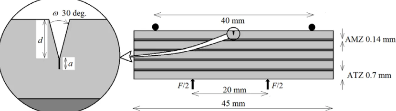
The geometry used in the modeling is shown in Fig. 1. The ATZ layers thickness was taken as 1
t = 0.7 mm and that of AMZ as t2 = 0.14 mm. It can be noted that the thicknesses in the model geometry are averaged from sample P0 and are close to sample P3.
Figure 1. The laminated specimen under 4-point bending loading and a detailed view on the v-notch. The specimen thickness is 4 mm (not specified in the figure). The layers thicknesses are averaged from sample P0 (see Tab. 1).
The sintering of the laminate samples requires firing the green stacks at 1550 °C and then cooled down slowly to room temperature (see Bermejo et al., 2006 for more details). Due to the change of temperature ∆θ and the mismatch in the coefficients of thermal expansion α , (i) in-plane bi-axial residual stresses are induced inside the layers. It is assumed that no plastic deformation occurs which is quite likely in this type of material, and the stresses can be easily calculated using the following formula
(
)
(
)
( 2) (1) (1) (1)* R (1)* R ( 2)* ( 2) (1) ( ) ( 2) ( 2)* ( )* R ( 2)* ( ) (1)* R 1 with for 1, 2 1 1 1 i i i E E V E E E E i E E V α α θ σ α α θ σ ν − ∆ = + − ∆ = − = = − + (2)where the volume ratio V equals to 6.25 in the idealized case (illustrated in Fig. 1) and takes R various values in the tested samples (Tab. 1). This scatter has an influence on the residual stresses as illustrated in Tab. 3.
Table 3. Thermal residual stresses in ATZ and AMZ layers for ∆ = −θ 1000 °C. R V 6.17 (P0) 7.01 (P1) 9.7 (P2) 6.01 (P3) 6.25 (model) (1) R σ (MPa) 94 84 62 96 93 ( 2) R σ (MPa) ̶ 579 ̶ 586 ̶ 602 ̶ 577 ̶ 580
Finally a notch with depth d is machined in the outer ATZ layer (Fig. 1) in order to promote crack initiation during the mechanical 4-point bending loading. This is carried out at very low loads so that no additional residuals stresses be induced. The actual notch depth values vary:
d =0.267 mm (P1), d =0.289 mm (P5), d =0.322 mm (P3) and 4 different depths are tested in the model: d =0.1, 0.2, 0.3, 0.4 mm.
Depending mainly on the notch depth, a crack was observed to initiate at the root of the notch either directly after cooling when machining the notch (Fig. 2, specimen P1) or later under the 4-point bending (4PB) loading (Fig. 3, specimen P3). Specimen P2 is not shown here, it exhibits similar results to P3 (i.e. a crack nucleation during the 4PB loading). The
corresponding load-displacement curves are plotted in Figs. 4a and 4b for both P1 and P3 specimens, respectively.
Fig. 4a: Load versus cross-head displacement of notched specimen (P1) loaded under four-point bending. A crack is already present in the notch due to thermal loading. No pop-in.
Fig. 4b: Load versus cross-head displacement of notched specimen (P3) loaded under four-point bending. A crack pops-in from the notch, causing a small drop in the load.
Figure 2. The sample P1 before (left) and after (right) 4-point bending loading (F= 80 N). A crack is already visible on the left figure (arrow) just after having machined the notch.
Figure 3. The sample P3 before (left) and after (right) 4-point bending loading (F = 80 N). No crack appears on the left figure prior to the mechanical loading.
It is important to mention that the nucleation of the crack at the notch tip does not cause catastrophic failure, as it would be the case in a notched monolithic ceramic. In both cases, following this nucleation, the crack penetrates the first compressive layer a short length around 0.025 mm, and then is arrested due to the shielding effect of the compressive stresses in the AMZ layers (for more details see Bermejo et al., 2006). If the mechanical loading is further increased, the crack kinks in the compressive layer at an angle around 16 deg. with respect to the horizontal line (Fig. 5).
In Fig.3, note that a dark line appears in both pictures within the AMZ layer. This is an edge crack caused by residual stresses which was analyzed in Chen et al. (2010) and more recently in Leguillon et al. (2015). It is shown in (Hbaieb et al., 2007) that if the stress state is such that it can cause the onset of an edge crack then it may also be responsible for the crack deflection.
It is a harmless fracture phenomena that does not affect the overall strength of the structure
for the investigated bending configuration, i.e. the edge crack runs parallel to the direction of applied stress. In general, the edge crack depth seems to be smaller or the same order than the thickness of the AMZ layer (Leguillon et al., 2015).
3. The coupled criterion
The coupled criterion (Leguillon, 2002) states that the crack nucleation in a brittle material occurs abruptly. The crack length jumps from 0 to a given small length a without any equilibrium state in between (note that, at the tip of a pre-existing crack the initiation in the strict sense does not take place, the jump is infinitely small, allowing to recover the Griffith criterion for the prediction of crack growth). Two conditions must be fulfilled simultaneously, the first one specifies that there is enough available energy to create a crack and the second that the tensile stress is greater than the tensile strength all along the presupposed crack path
P (i) c (i) c ( ) ( ) for 0 W a G a z z a δ σ σ − ≥ ≥ ≤ ≤ (3)
where δWP( )a is the change in potential energy between the cracked and uncracked states. Here z is the space variable in the direction of the future crack. It is assumed in (3) that this
Figure 5. The crack kinking into the AMZ layer.
new crack lies entirely in material (i) (this will be verified later), otherwise the formulas have to be modified accordingly (Leguillon and Martin, 2013).
Using the incremental energy release rate Ginc( )a (MPa mm)
inc P
( ) ( ) /
G a = −δW a a (4)
and pointing out that σ( )z is a decreasing function of z , (3) can be rewritten in a simple manner inc (i) (i) c c ( ) ( ) 1 and 1 G a a G σ σ ≥ ≥ (5)
In this system of inequalities the crack length a is up to now an unknown, this is the reason for the name “incremental” as opposed to “differential” when considering the limit as a→0
in (4) leading to the usual definition of the energy release rate G (MPa mm)
P P 0 lim a W W G a a δ → ∂ = − = − ∂ (6)
There are two ways to apply this coupled criterion, either performing full computations by FE (the FC approach, (Martin and Leguillon, 2004)), or using matched asymptotic expansions (the MA approach, (Leguillon, 2002)). These will be presented in the following section to model and predict the crack nucleation at the root of the v-notch.
4. Crack nucleation at the v-notch root – The FC approach
This is the most natural approach, it consists in calculating the tensile stress prior to failure and the change of potential energy in (3) using FE computations. But before going further, there are some worthwhile reminders.
The linear constitutive law takes the general form
(
in)
: ( )U
σ =C ε −ε (7)
The stress tensor is denoted σ , C is the elasticity operator relying on E and (i) ν depending (i) on the material, ε( )U is the linearized strain tensor, i.e. the symmetric part of the gradient of the displacement field U and εin is the inelastic part of the strain due to thermal effects. Assuming isotropic components, it can be written
εin =α θ(i)∆ I i=1, 2 (8) where I is the second order identity tensor.
In order to consider the variational formulation of the various problems we are interested in, we introduce a schematic view of the specimen, the corresponding 2D Figure 6. A schematic view of the
domain is denoted Ω (Fig. 6). The part Γ of the boundary 0 ∂Ω is clamped (i.e. U =0) and applied forces F are acting on the part Γ . The remaining is stress free. Let U be the space 1 of kinematically admissible displacement fields, i.e. vector fields being smooth enough (H1)
and fulfilling the boundary conditions on Γ The variational formulations of the pure 0. thermal problem (i.e. without mechanical loading F =0) and the pure mechanical problem (i.e. ∆ =θ 0) are respectively
1
th th in
el
Find such that : ( ) : ( ) d : : ( ) d Find el such that : ( ) : ( ) d . d
U U x x U U x F s ε ε ϕ ε ε ϕ ϕ ε ε ϕ ϕ ϕ Ω Ω Ω Γ ∈ = ∀ ∈ ∈ = ∀ ∈
∫
∫
∫
∫
C C C U U U U (9)Once discretized by FE, solving these variational equations amounts to solve the linear systems th th el el and = = U B U B (10)
where is the stiffness matrix, Uth and Uel the vectors of nodal unknowns and B and th B el
the right hand side members, respectively for the thermal and the elastic problem.
The thermo-elastic problem is a combination of these two and is obtained summing up the two equations in (9). Its potential energy is defined as the strain energy minus the work of external forces
(
in)
th el P 1 : ( ) d . d with 2 W σ ε U ε x F U s U U U Ω Γ =∫
− −∫
= + (11)Using (7) and (9) and developing (11) yields:
in th el th P 1 1 with : : ( )d . d . d 2 2 W W W U x F U s F U s δ δ ε ε Ω Γ Γ − = =
∫
C +∫
+∫
(12)These terms can easily be obtained from the FE computation of Uth and Uel as scalar products presumably accessible to any computer code
th th el el el th
1 1
. . .
2 2
W = B U + B U +B U (13)
4.1 The pure thermal problem F =0
As shown in Fig. 1, we consider for simplicity a sharp v-notch. However, if it is blunted as observed in Fig. 3 (notch root radius 0.02 mm) the predicted loading values have to be shifted upward by 12 % according to a recent parameter analysis and confirmed by Leguillon and Yosibash (2003) and Picard et al. (2006).
Figure 7. FE computations are carried out on ½ of the specimen geometry.
For symmetry reasons, the FE computations on the actual geometry are carried out on one half of the structure under the plane strain assumption (Fig. 7). Sliding is allowed on the supports (rollers), thus the kinematic boundary conditions reduce to U2 = on the support 0 and U1= along the symmetry axis. The tensile stress along this symmetry axis is first 0 computed, then W in (13) is calculated for various virtual crack lengths from a =0 (no crack) to a= + − (step t1 t2 d δ ), i.e. a crack emanating from the notch root, extending a
through the two first layers and impinging on the second interface (AMZ / ATZ). Then, the incremental and differential energy release rates (4) and (6) can be calculated respectively by
inc (0) ( ) ( ) ( ) ( ) W W a and ( ) W a W a a G a G a a a δ δ − − + = (14)
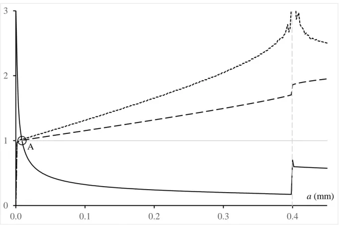
It is convenient to plot the dimensionless quantities: tensile stress σ( ) /a σc, incremental energy release rate inc
c
( ) /
G a G and energy release rate G a( ) /G in the same figure as shown c in Fig. 8 for a pure thermal problem (no mechanical loading) and d =0.3 mm (keep in mind that σc and G take different values on the two sides of the interface). Obviously, the two c conditions (5) are fulfilled at point A and only at this point located at a0 = 0.0089 mm for
θ
∆ = −955 °C (note that in the theoretical parts the temperature is mainly used as a parameter which allows varying the residual stresses). For a smaller cooling amplitude, the solid line curve is shifted to the left and the dashed one downward (see also Fig. 9 where a detailed view around point A is proposed) and there is no longer any point that satisfies both conditions (5) simultaneously.
Figure 8. The dimensionless: tensile stress (solid line), incremental energy release rate (dashed line) and energy release rate (dotted line) for ∆ = −θ 955 °C (no mechanical loading) and d =0.3 mm. The grey vertical dashed line is the interface ATZ / AMZ.
Figure 9. A detailed view around point A in Fig. 8. The crack jump at initiation is estimated to be a0 =0.0089 mm. The marks correspond to the nodes of the strongly refined mesh near the notch root (mesh size 0.002 mm).
0 1 2 3 4 0.0 0.1 0.2 0.3 0.4 a (mm) A 0.9 1.0 1.1 1.2
5.0E-03 7.5E-03 1.0E-02 1.3E-02
A
a (mm) a0
It is possible to plot the cooling amplitude −∆θ triggering the crack nucleation at the notch root while machining the notch (i.e. prior to any mechanical loading), as a function of the notch depth d (Fig. 10). Clearly, this cooling amplitude becomes unrealistic for notch depth smaller than 0.2 mm.
Figure 10. The cooling amplitude −∆θ triggering crack nucleation at the notch root prior to any mechanical loading, as a function of the notch depth d. Two symbols at the same abscissa correspond to two different meshes, a coarse and a refined one.
4.2 The pure mechanical problem ∆ =θ 0
A completely analogous analysis can be conducted for a pure mechanical problem with figures very similar to Figs. 8 and 9 (see Fig. 11). The crack jump is estimated as previously to a=0.0089 mm. 700 850 1000 1150 1300 1450 1600 1750 0 0.1 0.2 0.3 0.4 d (mm) −∆θ (°C)
Figure 11. The dimensionless: tensile stress (solid line), incremental energy release rate (dashed line) and energy release rate (dotted line) for F =209 N (no thermal effect) and d =
0.3 mm. The grey vertical dashed line is the interface ATZ / AMZ.
In parallel to the previous case, it is possible to plot the applied force F at crack nucleation at the root of the v-notch in the absence of thermal residual stresses (Fig. 12). As already mentioned in Sect. 4.1, the load value is underestimated by 12 % due to the rounding at the root of the notch.
0 1 2 3 0.0 0.1 0.2 0.3 0.4 A a (mm)
Figure 12. The critical applied force F at crack nucleation at the root of the v-notch in the absence of thermal residual stresses, as a function of the notch depth d. Two symbols at the same abscissa correspond to two different meshes, a coarse and a refined one.
4.3 The coupled thermo-elastic problem
Reached this stage, it becomes necessary to specify the value of the thermal residual stresses. In (Ševeček et al., 2013; Bermejo et al., 2006), it is assumed that the structure is free of stresses at 1250 °C, prior to cooling. Then, back at room temperature (∆ = −θ 1230 °C), the thermal residual stresses (calculated using (2)) are (1)
R
σ =114 MPa, (2) R
σ = −713 MPa in the present idealized geometry (Fig. 1). Nevertheless, some clues tend to show that these values are actually smaller. The indentation tests conducted on the ATZ layers in (Bermejo et al., 2006) do not allow drawing definitive conclusions but clearly the value 114 MPa, mentioned above, is an extreme and is rarely achieved. The scattering is large, it extends roughly from 30 to 110 MPa. The analysis in (Leguillon et al., 2015) of the onset of and edge crack in the compressive layers leads to a similar conclusion, residual stresses are more likely corresponding to a cooling lying between −800°C ( (1)
R
σ =74 MPa, (2) R
σ = −464 MPa) and
900
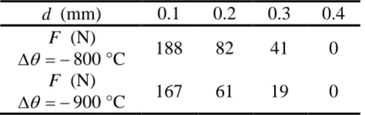
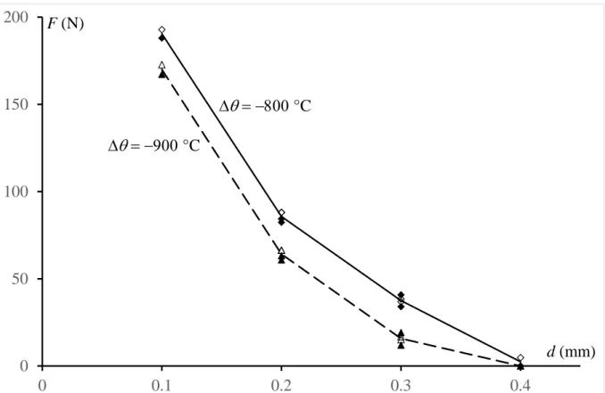
− °C (σR(1) =83 MPa, σR(2) = −522 MPa). Moreover, these values are consistent with the following developments. Within the above temperature range, according to Fig.10, the only structure that exhibits a crack prior to any mechanical loading is the one having the deepest notch d =0.4 mm. Using a figure similar to Fig. 9, the applied force triggering the crack onset during the 4-point bending test can be determined (Tab. 4).
These values are somewhat similar to those observed on the force/cross-head displacement curves recorded during the 4-point bending tests as illustrated in Fig. 5a. However, as already explained, it is clear that the variability observed in the geometry of the samples and the uncertainty on the residual stresses do not allow a more accurate comparison between the theoretical prediction and the measured values.
100 150 200 250 300 350 0 0.1 0.2 0.3 0.4 d (mm) F (N)
Table 4. The predicted applied force F triggering crack onset during the 4-point bending test, as a function of the notch depth d.
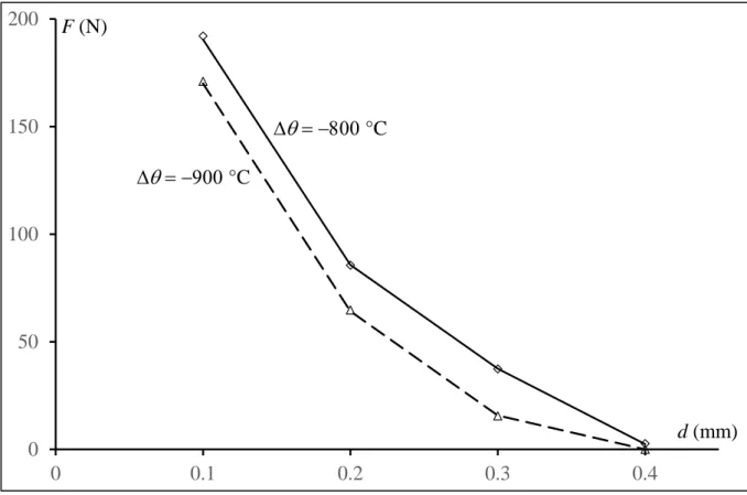
d (mm) 0.1 0.2 0.3 0.4 F (N) θ ∆ = −800 °C 188 82 41 0 F (N) θ ∆ = −900 °C 167 61 19 0
5. Crack nucleation at the v-notch root – The MA approach
As observed in the previous sections, the jump length a at crack onset is very small, around 0 0.009 mm (Fig. 9). This value is consistent with an approach based on asymptotic expansions, it is small compared to the layers thicknesses, to the notch depth and to the ATZ ligament width (the space between the notch root and the interface). Thus, the solutions to the above problems, prior to and following the crack nucleation, can be expressed using two expansions: an outer one describing the far field and an inner one giving more details on the near field (Leguillon, 2002; Leguillon and Sanchez-Palencia, 1987; Leguillon, 1993). These two representations must obviously coincide in an intermediate zone, which gives rise to the matching procedure based on the Williams’ series.
5.1 The pure mechanical problem ∆ =θ 0
It is the classic case of a reentrant corner in a homogeneous isotropic material (ATZ) under a symmetric loading, the Williams series in the vicinity of the notch root takes the very simplified form el el 1 2 ( , ) ( ) ... U x x = +C k r uλ ϕ + (15) 1, 2
x x are the Cartesian coordinates and ,r ϕ the polar ones originating from the notch root, they are mixed in the same relationship without confusion. The function r uλ ( )ϕ is defined in an unbounded domain containing a reentrant corner with opening ω , λ is the singularity exponent and u( )ϕ (MPa-1) is its associate mode. These two terms are solutions to an eigenvalue problem, they depend only on the notch opening ω (Fig. 1), here ω=30 deg.
0.502
λ= and u( )ϕ is symmetric with respect to the bisector (Leguillon and Sanchez-Palencia, 1987).
The coefficient el
k (MPa mm1-λ) is the generalized stress intensity factor (GSIF), it depends on the entire geometry of the specimen (and especially on the notch depth) and varies linearly with the load intensity (κ is the scaling coefficient) el
el el
k =κ F (16)
The GSIF is extracted from the FE solution using a path independent integral (Yosibash, 2012; Leguillon and Sanchez-Palencia, 1987; Leguillon, 1993; Labossiere and Dunn, 1999). It is the appropriate parameter to predict the crack onset at the notch root (Dunn et al., 1997). The coupled criterion (Leguillon, 2002) allows calculating the jump length a′ of the crack at 0 onset and the critical GSIF value (1)
c
(1) (1) c 0 (1) 2 (1) 2 c 1 (1) (1) el (1) c (1) 2 1 1 c (1) 2 c 1 0.0093 mm (1 ) 41.2 MPa mm (1 ) E G a A E G k k A λ λ λ ν σ σ ν − − − ′ = = − ≥ = = − (17)
where A is a geometric dimensionless coefficient depending only on the opening ω , here ω=30 deg. and A= 6.16. The jump length is quite close to the estimated value found using the FC approach (a0 = 0.0089 mm). As evidenced above, its smallness is mainly due to the properties of the ATZ layers.
For the 4 notch depths, the coefficient κel
in (16) (i.e. el
k for F = 1 N) is computed once for all, and the critical mechanical load leading to a crack onset in absence of residual stresses can be derived from (17). The resulting values never deviate more than 2.4% from the estimated ones in the FC approach (Fig. 12).
5.2 The pure thermal problem F =0
The only additional difficulty which arises in this case comes from the GSIF calculation. The integral used previously is path independent only if there is no volume and boundary forces in the vicinity of the notch root. This is not the case for a thermo-elastic problem (see the right hand side member of the first variational equation in (9)). An extra term should be added to the Williams series (15) (Leguillon et al, 2001)
(1) th th (1) (1) 1 2 (1) (1) ( , ) ( ) ( ) ... with (1 )(1 2 ) E U x x C k r uλ ϕ β θ rv ϕ β ν ν = + − ∆ + = + − (18)
Just as the leading term, this complementary term rv( )ϕ is defined on an unbounded domain containing a reentrant corner with opening ω . It must fulfil the equilibrium equation in a vicinity of the notch root and the special boundary conditions on the two faces σ.n=n (no other condition is required). It is easily calculated
(1) (1) (1) (1 )(1 2 ) ; 0 r v v E ϕ ν ν + − = = (19)
Then the GSIF kth =κth∆θ can be extracted from
th (1) th
1 2
( , ) ( ) ( ) ...
U x x +β ∆θ rv ϕ = +C k r uλ ϕ + (20) which meets all the requirements to compute the path independent integral.
The cooling amplitude ∆θ triggering crack onset at the root of the v-notch can be derived from the condition th (1)
c
k ≥k . Again, these values do not deviate more than 2.4% from the estimated ones in the FC approach (Fig. 10).
5.3 The coupled thermo-elastic problem
The coupled thermo-elastic problem is a combination of the two above situations and the actual GSIF k is simply the sum of the two previous ones
th el
k =k +k (21)
Then, using (16), the critical load triggering crack onset at the notch root during the 4-point bending loading is given by the simple formula
(1) th c el k k F κ − = (22)
These results are compared (Fig. 13) to those obtained by the FC approach (Tab.4), clearly the difference is very small.
Figure 13. The applied force F triggering the crack onset at the notch root during the 4-point bending test as a function of the notch depth d: ∆ = −θ 800 °C, MA approach (diamonds), FC approach (solid diamonds), average (solid line); ∆ = −θ 900 °C, MA approach (triangles), FC approach (solid triangles), average (dashed line).
5.4 Onset from a crack tip – The Griffith criterion
The singular exponent λ in (15) is very close to 0.5, i.e. to the classic crack tip singularity. Thus, we compared the above results with those obtained by neglecting the geometry of the v-notch and replacing it with a crack of the same depth. The Stress Intensity Factors (SIF) are calculated at the crack tip, using the already mentioned path independent integral, for both the thermal ( th
I
K ) and the elastic problem ( el I
K ). Then they are combined as in (21)
0 50 100 150 200 0 0.1 0.2 0.3 0.4 d (mm) F (N) ∆θ = −800 °C ∆θ = −900 °C
el th
I I I
K =K +K (23)
and K is compared to the critical value I (1) Ic
K (Tab. 1). This provides another approximate method to determine the applied force F triggering the crack onset at the notch root during the 4-point bending test (Fig. 14). No difference can be observed with the average value in Fig. 13.
Figure 14. The applied force F triggering the crack onset at the notch root during the 4-point bending test as a function of the notch depth d calculated using the Griffith criterion: ∆ = −θ 800 °C (diamonds), previous average (solid line); ∆ = −θ 900 °C (triangles), previous average (dashed line).
These results clearly make the MA approach very beneficial either under the coupled criterion or the Griffith form. Only a single elastic computation on the whole specimen, but without any crack extension, is required to calculate either the GSIF k or the SIF K which value is I compared to (1)
c
k or (1) Ic
K , whereas the FC approach needs a large number of computations in order to test various crack lengths and draw the curves shown in Figs. 8, 9, 11, etc.
Note that, in the present case the MA approach and the Griffith criterion give similar results but one has to keep in mind that the Griffith criterion is applied through a geometric simplification which validity becomes less and less appropriate as the opening ω increases (Leguillon, 2002). 0 50 100 150 200 0 0.1 0.2 0.3 0.4 d (mm) F (N) ∆θ = −800 °C ∆θ = −900 °C
6. Crack kinking in the compressive AMZ layer. 6.1 The crack growth
Before studying the crack deflection we must first analyze the crack propagation in ATZ, the penetration in the AMZ layer and the crack arrest. Obviously, this cannot be achieved by the MA approach which aims only at predicting the very beginning of the failure process, i.e. the crack nucleation.
The dimensionless tensile stress σ σ/ c, incremental energy release rate Ginc/Gc and energy release rate G G , deriving from the FC approach, are plotted in the same graph for / c d =0.3 mm, ∆ = −θ 800 °C, F = 34 N (Fig. 15). It can be observed (as in Figs. 8 and 11) that the energy release rate G tends to infinity when the crack tip approaches the interface and then decreases rapidly beyond the interface. It is the consequence of a strong singularity when the crack impinges on the interface (Leguillon and Sanchez-Palencia, 1992; Leguillon et al., 2000).
Figure 15. The dimensionless: tensile stress (solid line), incremental energy release rate (dashed line) and energy release rate (dotted line) for ∆ = −θ 800 °C, F =41 N and d =0.3 mm. The grey vertical dashed line is the interface ATZ / AMZ.
Once the crack is initiated, the conventional tool for fracture mechanics, i.e. the Griffith criterion based on the energy release rate G, can be used to predict the further growth and arrest. At point A the coupled criterion (5) is fulfilled: (1)
c / 1 σ σ = and inc (1) c / 1 G G = , the energy release rate G is larger than (1)
c
G (this would be more easily visible on a detailed view as in Fig. 9) and increases. Thus, after nucleation the crack continues to grow and reaches the interface where G is theoretically infinite. Then the crack penetrates the next layer (the crack deflection along a weak interface is excluded here) at least up to point B1 where G drops
0 1 2 3 4 5 0.0 0.1 0.2 0.3 0.4 A B a (mm) B 1 2
below (2) c
G . At B1, the extension length in AMZ is around b1 = 0.010 mm, this length
decreases as the notch depth increases. But it is clear that there is a significant amount of excess energy, G is far above (1)
c
G between A and the interface and then above (2) c
G between the interface and B1. The whole or only a part of this energy may be consumed to propagate
the crack beyond point B1 without going further than point B2, where the crack is closed and 0.
G = At B2 the extension length is b2 = 0.033 mm, slightly larger than observed (Fig. 4) but
again the geometric variability and the uncertainty on the level of residual stresses make it impossible to conclude to an overestimate. For ∆ = −θ 900 °C, it comes b1= 0.009 mm and
2
b = 0.027 mm. It may be also noted that in the absence of mechanical loading, under the sole effect of the temperature this length is b2 = 0.025 mm.
6.2 The crack deflection
For simplicity, we neglect the notch shape (its role is negligible now that the crack developed) and assume that a crack extends from the stress free bottom edge to its actual tip located, as observed in Fig. 4, at b2 = 0.025 mm (Fig. 16). At this crack tip the SIF
I
K vanishes (see Sect. 6.1). Then the load can be increased without any crack propagation until ( 2)
I Ic
K =K (Tab. 1), i.e. an additional load ∆ = 129 N, except if F conditions for crack kinking are met (Leguillon and Murer, 2008). This is what we are now interested in. The analysis will be conducted using the FC approach. It will be seen later that contrary to the crack nucleation at the notch root, the MA approach does not work in the present case because the crack jump cannot be considered as small with respect to other characteristic lengths of the structure and especially the penetration length b . 2
The FC procedure is the same as in Sect. 4 by varying now the length l of the crack branch (Fig. 17) instead of the crack length a. However, the situation is much different from the previous one because the incremental energy release rate is no longer a monotonically increasing function. Clearly, at point C1 (Fig. 17), if F <133 MPa then Ginc( )l1 <Gc( 2) and the coupled criterion is not fulfilled because of the energy condition whereas the stress condition is largely satisfied. At this point, for F =133 MPa, l1=0.042 mm, ( 2)
1 c
( )
G l =G and
( )
G l is a decreasing function of the crack length l (it can be shown that if ∂Ginc( ) /l ∂ = at l 0 a point then G l( )=Ginc( )l at this point). As a consequence the point under consideration is an arrest point. The load must be increased in order to grow the crack.
In addition, it must be immediately pointed out that l is larger than the penetration length 1 b 2 thus forbidding the use of the asymptotic approach (MA).
Figure 16. The crack extension b in 2 AMZ and the double deflection at an angle γ .
Figure 17. The dimensionless: tensile stress (solid line), incremental energy release rate (dashed line) and energy release rate (dotted line) for ∆ = −θ 800 °C, F =133 N.
If the load increases from F = 133 MPa to F = 172 MPa there is a stable crack growth between C1 and C2 following the load increments (Fig. 18). Then at C2, l2 = 0.189 mm,
(2)
2 c
( )
G l =G and the energy release rate becomes again an increasing function of the load, thus the crack growth becomes unstable.
The analysis of the crack extension beyond the point of instability C2 is outside the scope of this study. 0.0 0.5 1.0 1.5 0.0 0.1 0.2 C l (mm) l1 1
Figure 18. The dimensionless: tensile stress (solid line), incremental energy release rate (dashed line) and energy release rate (dotted line) for ∆ = −θ 800 °C, F =172 N.
During the 4-point bending test, the applied force to trigger a crack deflection at a given angle
γ = 5, 10, 16, 20, 30 deg. (Fig. 19) can be computed. The minimum is found at γ = 16 deg., showing that this direction is such that the conditions of the coupled criterion (5) are met first in a monotonic loading, it is in a surprisingly perfect agreement with the experimental observations (Fig. 4). 0 0.5 1 1.5 0 0.1 0.2 C l (mm) l0 2 l2
Figure 19. The applied load F triggering crack kinking in the compressive layer, function of the kink angle γ with b2 = 0.025 mm, for θ∆ = −800 °C (diamonds and solid line) and
θ
∆ = −900 °C (triangles and dashed line).
Note that the angle measured experimentally was around 16 deg. (Fig. 16) for that particular sample and it is checked that it satisfactorily corresponds to a minimum in the simulations (Fig. 19). In future work, different laminates with different AMZ thicknesses and compressive stresses will be analysed and compared with the predictions of this stress-energy criterion.
6.3 A complete scenario for failure of the v-notched specimen
By grouping all these results, we can reconstruct a complete scenario of the SENB test based on a force / displacement curve (Fig. 20). The correction due to the blunt notch (Sect. 4.1) has been taken into account, it slightly shifts upward the pop-in location (point 1 in Fig. 20). A comparison between Fig. 4b (specimen P3) and Fig. 20 can be carried out at least on the first stages of the bending test. Of course, the horizontal axis in Fig. 20 is the displacement h measured (computed) at the loading points, not the meaningless cross-head displacement in Fig. 4b. One can observe a good agreement on the pop-in location: it occurs for F = 52 N in the experimental curve whereas it is predicted at F = 46 N in the simulation. The difference is acceptable taking into account the geometric simplifications that have been made in the simulation. 75 100 125 150 0 5 10 15 20 25 30 γ (deg.) F (N) ∆θ = −800 °C ∆θ = −900 °C
Figure 20. Complete simulation of the SENB test, applied force F vs. loading point displacement h. (i) from the origin to point 1: elastic loading of the v-notched structure, (ii) at point 1: the crack initiates at the v-notch root and jumps to point B2 (Fig. 15), (iii) from
point 1 to point 2: elastic reloading of the cracked structure without crack growing or kinking, (iv) at point 2: the crack kinks and jumps to point C1 (Fig. 17), (v) from point 2 to point 3:
stable crack growth from C1 to C2 (Figs. 17 and 18), (vi) at point 3: beginning of the unstable
crack growth.
7. Summary and conclusion
The coupled criterion has proved its ability to predict the crack nucleation and its further propagation in the SENB experiments. The results coincide with the Griffith criterion thanks to a geometric approximation valid here but not anymore when the notch aperture increases. The Griffith criterion becomes ineffective whereas the coupled criterion still operates. This latter criterion allows also modelling other mechanisms that occur abruptly, like the crack penetration in the compressive layer and its deflection, without going through complex dynamic computations.
The asymptotic approach (MA) of the coupled criterion can be used successfully for the prediction of the crack nucleation at the v-notch root, but it cannot be employed in the other situations where it is difficult to identify a parameter being small compared to any other characteristic length of the structure. Then the full computation (FC) method, using FE calculations, becomes unavoidable. Of course a more thorough comparison with experiments is difficult because of the simplifications in the modelling, the variability of the geometry (Tab. 1) and the uncertainties on the measured parameters (Tab. 2). Moreover it would require knowing better the residual stresses after fabrication of the laminated ceramic plates and cut of the specimens.
Parametric analyses taking into account these uncertainties are in progress and dedicated measures will be carried out to determine the stress state before starting the tests. This will be
0 25 50 75 100 125 150 175 0 0.025 0.05 0.075 0.1 0.125 h (mm) F (N) 1 2 3
the topic of upcoming papers with, in particular, the aim to put in parallel the complete experimental and simulated load/displacement curves, up to the final failure (Fig. 20).
Acknowledgements
The present work has been carried out within NETME Centre established thanks to financial support of European Regional Development Fund under the Operational Program Research and Development for Innovation. The presented results have been obtained within NETME CENTRE PLUS (LO1202) project co-funded by the Ministry of Education, Youth and Sports within the support program, National Sustainability Program I.
References
Bermejo, R., Baudín, C., Moreno, R., Llanes, L., Sánchez-Herencia, A.J., 2007. Processing optimisation and fracture behaviour of layered ceramic composites with highly compressive layers. Composites Sci Technol 67, 1930-1938.
Bermejo, R., Torres, Y., Sánchez-Herencia, A.J., Baudín, C., Anglada, M., Llanes, L., 2006. Residual stresses, strength and toughness of laminates with different layer thickness ratios. Acta Materialia 54, 4745-4757.
Chen, C.R., Bermejo, R., Kolednik, O., 2010. Numerical analysis on special cracking phenomena of residual compressive inter-layers in ceramic laminates. Engineering Fracture Mechanics 77, 2567-2576.
Cornetti, P., Mantič, V., Carpinteri, A., 2012. Finite Fracture Mechanics at elastic interfaces. Int J Solids Structures 49, 1022-1032.
Cornetti, P., Pugno, N., Carpinteri, A., Taylor, D., 2006. Finite fracture mechanics: A coupled stress and energy failure criterion. Eng Fract Mech 73, 2021-2033.
Corning, I., 2012 Gorilla Glass Fact. Sheet.
Damani, R., Gstrein, R., Danzer, R., 1996. Critical Notch Root Radius in SENB-S Fracture Toughness Testing. Journal of the European Ceramic Society 16, 695-702.
Danzer, R., 2002. Mechanical Failure of Advanced Ceramics: The Value of Fractography. Key Eng Mat 223, 1-18.
Dunn, M.L., Suwito, W., Cunningham, S., 1997. Fracture initiation at sharp notches: Correlation using critical stress intensities. Int J Solids Structures 34, 3873-3883.
Griffith, A.A., 1921. The Phenomena of Rupture and Flow in Solids. Philosophical Transactions of the Royal Society A: Mathematical, Physical and Engineering Sciences 221, 163-198.
Hbaieb, K., McMeeking, R.M., Lange, F.F., 2007. Crack bifurcation in laminar ceramics having large compressive stress. Int J Solids Structures 44, 3328-3343.
Irwin, G.R., 1962. Crack-Extension Force for a Part-Through Crack in a Plate. Journal of Applied Mechanics 29, 651.
Labossiere, P.E.W., Dunn, M.L., 1999. Stress intensities at interface corners in anisotropic bimaterials. Eng Fract Mech 62, 555-576.
Lange, F.F., 1989. Powder processing science and technology for increasing reliability. J. Am. Ceram. Soc. 72, 3-15.
Launey, M.E., Ritchie, R.O., 2009. On the Fracture Toughness of Advanced Materials. Advanced Materials 21, 2103-2110.
Leguillon, D., 1993. Asymptotic and numerical analysis of a crack branching in non-isotropic materials. Eur J Mech A Sol 12, 33-51.
Leguillon, D., Sanchez-Palencia, E., 1992 Fracture in heterogeneous materials, weak and strong singularities, In proc.of: European Conference on New Advances in Computational Structural Mechanics, 229-236.
Leguillon, D., 2002. Strength or toughness? A criterion for crack onset at a notch. European Journal of Mechanics, A/Solids 21, 61-72.
Leguillon, D., Lacroix, C., Martin, E., 2001. Crack deflection by an interface - Asymptotics of the residual thermal stresses. Int J Solids Structures 38, 7423-7445.
Leguillon, D., Lacroix, C., Martin, E., 2000. Matrix crack deflection at an interface between a stiff matrix and a soft inclusion. Comptes Rendus de l'Academie de Sciences - Serie IIb: Mecanique, Physique, Chimie, Astronomie 328, 19-24.
Leguillon, D., Murer, S., 2008. Crack deflection in a biaxial stress state. Int J Fract 150, 75-90.
Leguillon, D., Sanchez-Palencia, E., 1987. Computation of singular solutions in elliptic problems and elasticity. John Willey & Son, New York.
Leguillon, D., Yosibash, Z., 2003. Crack onset at a v-notch. Influence of the notch tip radius. Int J Fract 122, 1-21.
Leguillon, D., Martin, E., 2013. The strengthening effect caused by an elastic contrast -part I: the bimaterial case. Int J Fract 179, 157-167.
Leguillon, D., Ševeček, O., Martin, E., Bermejo, R., 2015. Edge cracking due to a compressive residual stress in ceramic laminates. C. R. Mécanique 343, 192-198.
Martin, E., Leguillon, D., 2004. Energetic conditions for interfacial failure in the vicinity of a matrix crack in brittle matrix composites. Int J Solids Structures 41, 6937-6948.
Morrell, R., 1999. Fractography of Brittle Materials pp 86. Teddigton: National Physical Laboratory.
Picard, D., Leguillon, D., Putot, C., 2006. A method to estimate the influence of the notch-root radius on the fracture toughness measurement of ceramics. Journal of the European Ceramic Society 26, 1421-1427.
Rao, M.P., Lange, F.F., 2002. Factors Affecting Threshold Strength in Laminar Ceramics Containing Thin Compressive Layers. J Am Ceram Soc 85, 1222–28.
Ševeček, O., Bermejo, R., Kotoul, M., 2013. Prediction of the crack bifurcation in layered ceramics with high residual stresses. Eng Fract Mech 108, 120-138.
Taylor, D., Cornetti, P., Pugno, N., 2005. The fracture mechanics of finite crack extension. Eng Fract Mech 72, 1021-1038.
Yosibash, Z., 2012. Singularities in Elliptic Boundary Value Problems and Elasticity and Their Connection with Failure Initiation. Springer, New York.