HAL Id: in2p3-00996645
http://hal.in2p3.fr/in2p3-00996645
Submitted on 6 Apr 2020
HAL is a multi-disciplinary open access
archive for the deposit and dissemination of
sci-entific research documents, whether they are
pub-lished or not. The documents may come from
teaching and research institutions in France or
abroad, or from public or private research centers.
L’archive ouverte pluridisciplinaire HAL, est
destinée au dépôt et à la diffusion de documents
scientifiques de niveau recherche, publiés ou non,
émanant des établissements d’enseignement et de
recherche français ou étrangers, des laboratoires
publics ou privés.
Main results on the RF amplitude and phas eregulation
systems in operation at GANIL
A. Joubert, B. Ducoudret, J.C. Labiche, J.M. Loyant
To cite this version:
A. Joubert, B. Ducoudret, J.C. Labiche, J.M. Loyant. Main results on the RF amplitude and phas
eregulation systems in operation at GANIL. Tenth International Conference on Cyclotrons and their
Applications, Apr 1984, East Lansing, United States. pp.367-370. �in2p3-00996645�
$9-I
MAIN RESULTS ON THE RP AMPLITUDE AND PHASE REGULATION. SYSTEMS IS OPERATION AT GANIL
A. Joubert, B. Ducoudret, J, C. Labiche, J. M. Loyant GAKIL - CAEN - FRANCE
ABSTRACT 2. SERVO TUNING SYSTEMS
The •general features of the amplitude and phase regulations aad their control systems are briefly re viewed. These feedback control systems are fully under the control of the main computer aided by dedicated CAMAC microprocessors for actions such as starting, parameters tuning or phase stability surveying. Nume rous results obtained with spectrum analysis method give the actual RF purity and the residual modulation and crossmodulation noise level for all RF signals picked up in the RF resonators. A typical value for the noise immunity is 80 dB belov the carrier at
100 Hz deviation. Another set of results gives the ac tual long term phase drift between resonators (< 0.8 RF
degree within 6 hours). The stability of the RF phases
is confirmed by on line beam phase measurements. 1. INTRODUCTION
The GANIL RF systems have been described elsewhere 1 2 3
* . However it seems useful to briefly recall
their main features :
Common required characteristics : - Frequency range :
(the working frequency for a given particle is the sane for all the resonators) - Dee voltage stability : - Phase stability :
6.5 to lU MHz
•v. 1 0 . *
< 0.5°
Configuration of the GANIL resonators
Injector SSCI ** and SSC2 «* Type
XA
(1 stem canti lever )XA
(1 stem hanged)x/a
(2 stems slo ping) tuning mode 2 capacitive novable panels in lateral po sition 2 capacitive novable panels in lateral po sitionMax Dee volta ge peak value
(kV)« (a) (b)
1 capacitive novable panels at the near po sition of the dee 20 20 100 100 250 Notes :
* Values given for the min. (a) and the max. (b) fre quency
** 2 identical resonators in opposite position
The quality of the amplitude and phase regulation systems is dependent on the precision of the servo tu ning systems. « AF MME H T I F » _ MUM
nmuFcma
mm*. ^ ^
MUIMmm
tr «USEam.
mm.
mm
I K 1/pcm
««ft. Fig. 1The same principle has been used for all the 6 GANIL resonators Pig 1. One combines the action of a rotating loop (fast réponse but small correction ran
ge : ± 20 RF degrees) and of the capacitive movable
pa-nel(s) : (slow action but non limited correction ran ge). Because of small mechanical vibrations obse-red above 20 Hz, the unity gain bandwidth of these s-- vo-loops had to be reduce to 7 Hz in SSC's resonator with an adapted multipoles low-pass filter. So the
tuning of the resonators is remained within t 3°.
3. AMPLITUDE REGULATION SYSTEM
3.1 Description
The amplitude loop structure is shown in Fig. 2. To carefully preserve the same working point and therefore the open-loop gain constant over the whole amplitude range, one has two automatic gain control de vices : the first using analog divider and multiplier circuits keeps constant the transfer function of the RF detector, the second, by back control of a RF atte nuator, keeps constant the RF gain of the amplitude modulator.
The table below summarizes the main characteristics :
Open l o o p g a i n a t 300 Hz 57 dB 6G0 HZ 51 dB Small s i g n a l u n i t y g a i n bandwidth 12 kHz R e g u l a t i o n a c c u r a c y < 10 * A b s o l u t e thermal d r i f t < 10 SV / ° C ( i n c l u d i n g dee v o l t a g e probe RF d e t e c t o r and o f f s e t v o l t a g e d r i f t ) R e f e r e n c e v o l t a g e g e n e r a t o r s t a b i l i t y < 10 6 per day
The predicted characteristics have been reached for all the resonators, nevertheless a difficulty about the Absolute dee voltage measurement is still not solve : (case of the 2 SSC's resonatcrs) direct low level reading method, X-ray calibration and beam turn separation are in agreement within only
155-«F m
.raiMjre vratEjraE
Fig. 2
Watching the accelerated beam, the SSC dee voltage long term stability 13 good enough but difficult to know precisely because the measurement method do not include the small mechanical variations regarding the dee to HF probe distance. The following spectrum ana lyses in Fig. 3 proves the good amplitude noise immu nity (residual modulation coefficient less than t0~"). All these -spectra have been done the beam being fully accelerated. fUT.TOP FILTER BANDWIDTH l«,5Hl u
VM»AJiJLjuJl
-..A.n
400 6 0 0 FREQUENCE^ FIAT.TOP FILTER BANDWOTH 3 6 5 H is V s'
5 10 15 20 FREQUENCE ( K H I ) Fig. 33.S Computer Control and Operation
The amplitude regulation systems are controlled by U dedicated CAMAC microprocessors (injector» bun-cher, SSCI, SSC2) which are in charge of ;
a. the voltage reference control itself coming from the main computer.
b. the starting operation {choice of low level RF voltage for frequency tuning operation, rising the RF dee voltage up to the asked level). c. The automatic gain control through the atte nuator (§ 3.1 ).
d. the on-off actions.
Before starting, all the transmitter and resonator parameters (i.e. movable panel or variable condensa-tor positions ) are verified after having read the wor king frequency value.
The access to the RF voltage levels and the ampli tude regulation status via the main computer is easy by means of special tasks^.
U. PHASE REGULATION SYSTEM
U.I Description
Common for all the GANIL resonators this complex system has 2 goals :
a. to clean the RF dee voltage of any parasitic phase noise modulation in the range of 0 to
15 kHz. This role is devoted to the fast phase regulation devices.
b. to make possible precise phase adjustemen^s between RF systems and not only between the two re3o iators of one SSC but also between injector, buncher, and the two SSC for beam tuning. Of course this must be possible for any value of the GANIL frequency range and the phase values keeped constant as well as possible within ± 0.5 RF degree.
This last part is the most complex of the whole system : it is fully controlled by a dedicated CAMAC microprocessor and uses stepping phase shif ters combined with continuous mechanical phase shifters. A HP vector voltmeter is used as a preci sion on-line phasemeter.
I—fe
pmtwtwt
m
sum m
2TOS OTfER i w t m i w HiimRK PISE M U RI
i w t m i w HiimRK PISE M U R (HUEam.
PHASE KflMMW ' FflOM KsmmL _
OTL KM. TO /ta. F i g . hThe Fig. h shows the detailed structure. The RF signal provided by the master generator is distributed in 6 ways. Every one is itself divided in two si gnals : the first is sent to a phase modulator and then to the related RF transmitter, the second is the floating RF phase reference for the fast phase regulation device, "Floating" means that any phase ad justments made before the last divider do not disturb the fast phase loop.
Outside of the CAMAC system, the other important part is the phase-measurement system. The 6 back RF signals given by the RF resonator probes are conducted by phase balanced cables (equal electrical length) connected to the vector- voltmeter through a well balanced multiplexer.
h.2 Operation and Results
Injector resonator gives the phase reference, for all RF systems, except resonator n° 2 of both SSC (for vhich the phase reference is taken on the opposite re sonator n° 1 ).
The 5 relative phase values (injector-buncher i injector-SSC1 reson. 1 ; injector-SSC2 reson. 1 ; SSC1 reson. 1-reson. 2 \ SSC2 reson. 1-reson. 2) are perio dically measured by a local surveying program vhich sends an error message to the main computer when a phase drift greater than 0.2° relatively to the refe rence value is detected. Then the operator has to get informations by reading status word and, if necessary, can ask the correcting action.
The initial setting of the phase values ia done by the main computer through the console keyboard. It ia also possible to control any phase value in pseudo-analog mode by hooking one pseudo-knob.
Hevet-theless thia laat action requests to perform a complicated process (dedicated phase control micro processor) and the final answer may come slowly (seve ral ten seconds due, for its main part, to the slow motion of the mechanical phase shifters). That is not very convenient for on line beam tuning. An improve ment is in progress to control directly by pseudo-knob the phase reference of the fast phase loop using direc tly the electronic phase modulator and therefore by passing the local processor. In this.way we hope to have ± 10° phase variation capability. Consequently the operator will find the correct phase value by wat ching the beam.To know the precise phase value, then he has to restore the local processor.
Jff"
I
RAT.TQP FILTER BANDWIDTH I4,5HIi
IJ
VJU
^ - ^ \ r ^ f l ^ W ^ Yv^ -w^ - > ^ \sss . v-L
ma 200 AOO 600 800 FREOUEHCEW 10 10!
FLAT.Î0P FILTER BAH0WOTH US Hii
L \s
4 B FREQUENCE (KH^ S S C I , r « s l . $ f s iOOk/, r= 3.52 M H z . . Fig. 5Various spectrum analyses Fig. 5 and long term re cording show that the overall stability of ttt whole phase control system is better than ± 0.2°.
The phase noise is really very small (better than 0.05°) and the RF spectral purity (given by
radio-frequency spectrum analyses in a bandwidth of 10 kHz around the carrier) is always better than 80 &B for any GANIL resonator : Fig. 6.
0_ FILTER RESOLUtlOH I 0 H .
j
,
«
•-AAM
V U
\
W V * W W V A / V U J vW U W V w y w v
-_500HL 400 300 200 100 0 100 200 300 400 * 5 0 0 H ,Pilot aynhhcziscr : 9.54 MM*, ("phase noise refer.)
f
FILTER. RESOLUTION I0H«A ; J»
y
A ' l
«
, . . .
/u/^u
V w l / i / w . .
- 5 0 0 m 400 300 200 100 0 100 200 300 400 + 5 0 0 H > 0
FILTER RESOLUTION : lOHt
— w > ~ ~ W w i . . i
±
, < ^ W r ^ V r \ « n •%„ - Suit 4 3 I I 0 I 2 3 4 1- SonSSC2,res.2 : 3.52MHz, lOOkV* (Dee voJtoge).
Fig. 6*
This operating system has now been used for almost 1 year with on line computer control and fortunately it works very well, without serious troubles or fai lures .
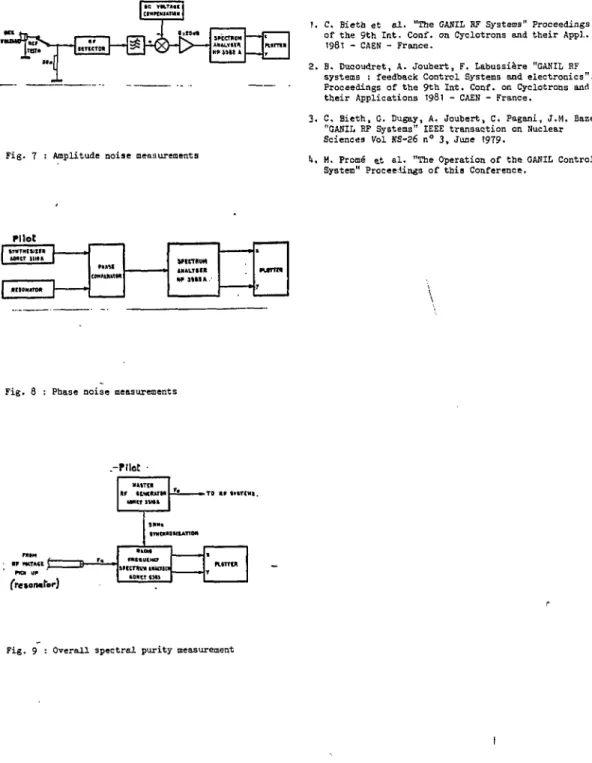
5. MEASUREMENT METHODS
Fig. 7, 8 and 9 show the measurement methods in use to record the 3 kinds of spectra.
SMCTHUM AMU.VHH H* 3311 4 SMCTHUM AMU.VHH H* 3311 4 pumx SMCTHUM AMU.VHH H* 3311 4 pumx SMCTHUM AMU.VHH H* 3311 4 REFERENCES
1. C. Bieth et al. "The GABIL RF Systems" Proceedings of the 9th Int. Conf. on Cyclotrons and their Appl.
1981 - CAEN - France.
2. B. Duooudret, A. Joubert, F. Labussière "GANIL RF systems ! feedback Control Systems and electronics". Proceedings of the 9th Int. Conf. on Cyclotrons and their Applications 1981 - CAEN - France.
Fig. 7 : Amplitude noise measurements
3. C. Bieth, C. Dugay, A. Joubert, C. Pagani, J.M. Baze "CANIL RF Systems" IEEE transaction on Nuclear Sciences Vol NS-26 n° 3, June 1979.
It. M. Promé at al. "The Operation of the GANIL Control System" ProceeAing3 of this Conference.
Pilot
tTMTHttlHR k M t r l i l t ft
COM'MIMM 1MM.Y»CR W 3111A . t
P U T T » y tTMTHttlHR
k M t r l i l t ft
COM'MIMM 1MM.Y»CR W 3111A . t
P U T T » y COM'MIMM 1MM.Y»CR W 3111A .
t P U T T » y COM'MIMM 1MM.Y»CR W 3111A .
t P U T T » y
1
COM'MIMM 1MM.Y»CR W 3111A . t P U T T » y RMOMintM 1MM.Y»CR W 3111A . t P U T T » y
Fig. 3 : Pbase noise measurements
PlIM P.F » W « l ("""" PKM UP fr«*ofwtbr) -rilôC MMTCR RF UWftftTM
UN» 11»» »TO nr tmcMi.
9MH* «THBHOIMIATIM «MHO mtmuKHcr SHCTHV* 1HU1SCP WHIT CHI