HAL Id: cea-02394083
https://hal-cea.archives-ouvertes.fr/cea-02394083
Submitted on 6 Dec 2019HAL is a multi-disciplinary open access
archive for the deposit and dissemination of sci-entific research documents, whether they are pub-lished or not. The documents may come from teaching and research institutions in France or abroad, or from public or private research centers.
L’archive ouverte pluridisciplinaire HAL, est destinée au dépôt et à la diffusion de documents scientifiques de niveau recherche, publiés ou non, émanant des établissements d’enseignement et de recherche français ou étrangers, des laboratoires publics ou privés.
Influence of the thermomechanical process on the
behavior of 6xxx aluminum alloys under ion irradiation
V. Garric, K. Colas-Leroux, B. Kapusta, P. Donnadieu
To cite this version:
V. Garric, K. Colas-Leroux, B. Kapusta, P. Donnadieu. Influence of the thermomechanical process on the behavior of 6xxx aluminum alloys under ion irradiation. Meeting of the International Group on Research Reactors (IGORR - 2019), Mar 2019, Amman, Jordan. �cea-02394083�
1
INFLUENCE OF THE THERMOMECHANICAL PROCESS ON THE
BEHAVIOR OF 6XXX ALUMINUM ALLOYS UNDER ION IRRADIATION
V. GARRIC, K. COLAS, B. KAPUSTA
DEN-Service d’Etudes des Matériaux Irradiés, CEA Université Paris-Saclay F-91191, Gif-sur-Yvette
P. DONNADIEU
Univ. Grenoble Alpes, CNRS, Grenoble INP, SIMaP F-38000 Grenoble
ABSTRACT
Aluminum alloys have been widely used in nuclear research reactors (NRRs) since the 1960s. This choice is mainly due to the very high neutron transparency of such alloys coupled with the low temperature of NRRs. In pressurized NRR, thicker sections are designed to achieve higher mechanical strengths, but issues arise on the irradiation damages in the thickness. Several microstructures of a typical aluminum alloy from the 6xxx series where achieved and samples with the obtained different microstructures were irradiated with different ion fluxes in order to reproduce the irradiation behavior that can be observed in reactor. The results obtained here are compared to literature results from neutron-irradiated samples and modelled in order to predict swelling behavior under irradiation.
1.
Introduction
Aluminum based alloys are materials of choice for NRR due to their high thermal conductivity, low gamma heating, low activation and high neutron transparency under irradiation. Research reactors use 5xxx and 6xxx aluminum alloys for their core components to limit the activation under neutron flux. A good compromise between corrosion behavior and high mechanical strength is obtained with the 6xxx series. While increasing the safe and efficient use of NRRs, the manufacturing of such alloys can be challenging in terms of thermomechanical processing: indeed the mechanical properties of those alloys are mainly induced by very specific thermal treatments, which usually consist of annealing, quenching and artificial ageing. Due to a wide use of aluminum alloys in the automotive industry, the thermomechanical processing and its influence on the mechanical properties is already well known and documented in the literature([1], [2]). However, one of the key differences between the automotive industries applications and those of NRRs is the thickness of the manufactured components. Indeed, most of the available research data is available for thin components while the nuclear industry uses thicker ones, especially in the case of pressurized NRRs. Due to this specificity, quenching has to be carefully monitored and understood to obtain a very homogeneous material. In this study, using a typical thermal processing sequence for 6xxx aluminum alloys but varying the quenching rate, we propose to monitor the microstructure formed in aluminum components prior to irradiation in NRRs, observing the formation of dispersoïds and nanometric phases also known as hardening phases. Then, irradiating the different tempers with ion beams, targeting various DPA rates and fluences, we examined a variety of microstructures inside the material and examined in particular the formation of voids and cavities, in order to highlight the influence of the microstructure on the swelling induced by three-dimensional defects.
2.
Material and methods
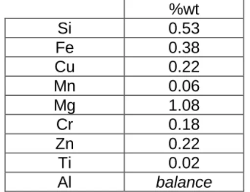
The base material used in this study was a 6061 alloy with the composition given in Table 1. Three 10cm side cubes specimens were extracted from a larger block and machined in order to insert thermocouples at three different positions. Then, each cube followed the same
2
thermal treatment excepted the quenching rates induced by different quenching fluids. The thermal treatment itself consists of an annealing at 530°C during at least 12h, then a quenching followed by an artificial ageing of 12h at 175°C with a maximum delay of 8h between quenching and ageing. One cube was quenched in water (typical T6 temper), another in oil and the last one in air. TEM specimens were extracted from various positions of the cubes, and electropolished using a 30% nitric acid in methanol solution. The quenching rates were obtained after simulation using CAST3M finite elements code. Irradiation conditions were carefully chosen to be as representative as possible of the NRR environment.
%wt Si 0.53 Fe 0.38 Cu 0.22 Mn 0.06 Mg 1.08 Cr 0.18 Zn 0.22 Ti 0.02 Al balance
Table 1 : Composition of selected 6061 alloy (%wt)
3.
Initial microstructure after thermomechanical treatment
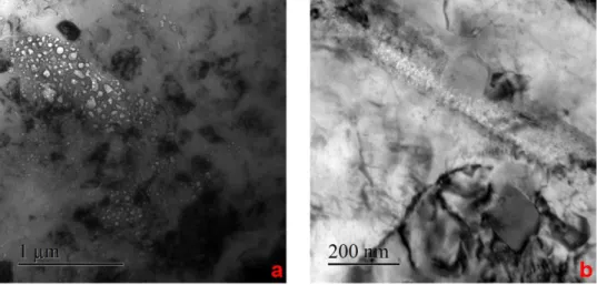
Results from the thermocouples showed a steady and slow quenching rate inside the air-quenched cube (<0.1°C/s). Water temper showed a drop of more than 10°C/s in terms of quenching rate in an area of about 12 mm as illustrated Figure 1. Due to experimental constraints on the oil quench (a sealed oven), no suitable data were acquired. Therefore, we assume the quenching rate to be between the air and water temper. The microstructure observations at submicronic scale are presented in Figure 2. Figure 2.a and b both picture dispersoïds in the water temper. Figure 2.a presents a low density of typical alpha dispersoïds inside the material near the surface of the block. Water temper at higher depth however, shows a higher density of dispersoïds as seen in Figure 2.b. These dispersoïds are the usual alpha AlMnSi phase. In the oil temper (Figure 2.c), the density of particles is higher than for the water temper sample while more elongated phases appear which were not observed in the water-temper samples. The air temper sample which has the slowest quench rate, presents a very high density of both large and regular particles as seen in Figure 2.d. Usual alpha dispersoïds are identified but new extremely large plates heterogeneously growing from alpha dispersoïds are observed. Figure 3 presents the microstructure with higher magnification (nanometric scale). All pictures here are observed along the <100> zone axis, in order to highlight the typical hardening nanophases. Contrarily to what has been observed at the submicronic scale for the water temper sample, Figure 3.a pictures a very high density of nanoprecipitates near the surface of the cube while Figure 3.b seems to present a lower density at higher depth. Oil temper (Figure 3.c) also exhibits a high density of nanometric phases but with a smaller size compared to the water temper samples. Finally, Figure 3.d pictures a dark field image in the air temper, produced with the selection usually employed to reveal hardening precipitates in 6XXX alloys. Inside the material, no signal of such particles is observed. Nevertheless, some precipitates appear located preferentially on dislocations. This observation suggests, a dislocation could be a preferential site for precipitation of nanophases in air temper samples. Additional observations such as HRTEM are needed to confirm this.
Figure 1 : Simulation of the quenching rate inside the water quenched cube
3
Figure 2: Typical microstructure of each temper at submicronic scale seen in TEM (a): Water near surface, (b): Water at mid thickness, (c): Oil, (d): Air
Figure 3: Typical microstructure of each temper at nanometric scale seen in TEM (a): Water near surface, (b): Water at mid thickness, (c): Oil, (d): Air (Dark Field)
4
Correlated observation of both scales, Figure 2 and Figure 3, pictures an opposite behavior of precipitation correlated with the quenching rate: a higher quenching rate implies a higher density of hardening particles while lowering the density and chemical/crystallographic variety of dispersoïds while a lower quenching rate seems to imply a very heterogeneous precipitation of submicronic phases at the expense of the density of hardening phases.
4.
Post irradiation observation
In the following part, specimens of each major tempers (air, oil, water near center, water near surface) were irradiated for each irradiation condition. This part focuses on qualitative observation of the voids and irradiation damages. Modelling will be presented and discussed on part 5. For brevity’s sake, only two irradiation experiments and results will be detailed in this proceeding.
Paragraph Beam Ion Flux (ion/cm2.s) Energy (MeV) Time (h) Fluence (ion/cm2) Targeted DPA (observed area) 4.1 Single Au4+ 2.1011 3.5 52h 3.69.1016 100-150 4.1 Single Au4+ 2.1011 3.5 36h 1.96.1016 60-90 4.2 Triple He+ 6.17.1011 0.5 5h30 9.95.1015 35 Si+ 6.17.1011 2.5 5h30 9.95.1015 W9+ 3.8.1011 13 5h30 6.15.1015 Not detailed here Triple He+ 6.17.1011 0.5 5h30 9.95.1015 18 Si+ 6.17.1011 2.5 5h30 9.95.1015 W9+ 1.9.1011 13 5h30 3.1.1015 Single W9+ 3.8.1011 13 5h30 6.15.1015 <35 Mixed W9+ 3.8.1011 20 5h30 7.5.1015 (max) 15 to 50 Mixed W9+ 2.1011 20 5h30 4.1015 (max) 5 to 25 Mixed W9+ 1.1011 20 5h30 2.1015 (max) 2 to 10
Table 2 : Summary of ion irradiations conditions as conducted at the Jannus-Saclay facility. Temperature was set to 20°C in all experiments
4.1 Single beam irradiation with gold ions
Single beam irradiation with gold ions have been performed in order to obtain high damage values. Using a constant flux, two irradiation durations were used, allowing the observation of 100-150 DPA for longer duration and 60-90 DPA for the shorter duration. More details on the experimental conditions are given in Table 2.
Figure 4: Observation of single beam irradiation on water temper : voids around a dissolved dispersoïd in a 60 DPA zone (a) and larger voids in a 100 DPA area (b)
5
Figure 4 pictures many different effects of the irradiation on water temper. On Figure 4.a (60 DPA), a dispersoïd is seen being dissolved and amorphized while voids begin to grow on its edges. Looking closely, background microstructure seems inhomogeneous and undefined. The microstructure observed in the 100 DPA sample exhibits many small grains all over the material. Analysis of such grains gives an average grain size of 100 nm while the material prior to irradiation presented a 100 µm average grain size. This effect was observed in the past ([3]) in different aluminum alloys and is believed to be linked with the dislocation density present in the material before irradiation. A very high density of voids is also observed in Figure 4. These voids are all aligned along what is believed to be former grain boundaries.
Figure 5 presents air temper with two different damage levels. The 100 DPA sample presents areas with a high concentration of large voids surrounded by areas without any void. This phenomenon was observed in all the air temper specimens. In order to further understand this phenomenon, an air-tempered specimen with a low DPA value was prepared. Figure 5.b pictures the air temper at 10 DPA. Large and elongated plate is seen dissolving in the matrix while the alpha dispersoïd seems to remain crystalline and steady at such low damages.
4.2 Triple beam irradiation
Acknowledging the results of single beam irradiation, triple beam were performed in order to assess the role of helium and silicon which are produced during inside reactor irradiations with neutrons. Due to technical limitations, a lower DPA had to be targeted.
Figure 6 shows helium bubbles seen in air temper specimens. The aspect, size, distribution and location due to the implantation is different besides DPA considerations. Figure 7 presents EELS spectra obtained in two different areas in a water temper specimen. The data taken in a bubble free area, shows no peculiar edge. However, data taken from a helium concentrated area presents a peak around 25 eV that is known to be a specific edge for Helium. Finally, Figure 8 shows bubbles in a cross section oil temper specimen. Figure 8.a presents a band of bubbles of about 400 nm, which is in good accordance with our calculations. Figure 8.b, pictures helium bubble distribution, which presents the same size and distribution as seen in air and water temper with the same irradiation conditions.
Triple beam irradiations presented a different behavior toward void and bubble formation. This effect was mainly induced by the helium implantation. If this study pictured a primary role of helium in the formation of small and stable voids, more has to be carried out in order to identify clearly the role of silicon and DPA and DPA rate on the formation of voids and bubbles.
Figure 5: Observation of single beam irradiation on air temper: large void concentration in a 100 DPA area (a) and partial disolution of an elongated dispersoid at low damage value (10 DPA) (b)
6
Figure 6: Helium bubbles seen in air temper with EFTEM elastic imagery
Figure 7: EELS spectrum in a bubble free area (a) and helium concentrated area (b)
7
5.
Modelling
8
Figure 9 represents a summary of various studies of void swelling in aluminum alloys from the literature ([3-8]) as a function of DPA, alloying elements or temperature. From this data, several observations can be made. First, for all observed irradiation conditions, alloyed aluminum swell less than pure aluminum. Secondly, a linear relation appears between swelling and DPA. In the ions irradiation experiments from Jahnke, many temperatures where tested. These observations present a peak of swelling at a given temperature which depends on the damage dose. This result is in good accordance with the general behavior of metallic materials under irradiation [10-11]. Finally, concerning the 6xxx alloys themselves, it seems that the ageing temperature, which is directly linked to the density of nanometric phases, has a great influence on the alloy swelling.
In this study, the Brailsford and Bullough (B&B) ([12]) model and equation as written in 1972 will be presented, explained and tracks about empirical improvements will be given. The three equations defining the B&B model are given as following:
(1) Δ𝑉 𝑉 (%) = 𝑆𝐹(𝜂)𝐾Δ𝑡 (2) 𝜂 = 400 exp [−𝐸𝑣 𝑚 𝑘 ( 1 𝑇𝑠 −1 𝑇)] (3) 𝐹(𝜂) =2 𝜂[(1 + 𝜂) 0.5− 1 −1 2𝜂𝑒𝑥𝑝 (− 𝑄 𝑘( 1 𝑇− 1 𝑇𝑡 ))]
Symbol Meaning Unit Type
S Incubation None
Constant to determine empirically
K DPA rate DPA/s Irradiation
parameter Δ𝑡 Time s Irradiation parameter 𝐸𝑣𝑚 Vacancy diffusion activation energy J Constant of the material 𝑇𝑠 Swelling activation temperature K Constant of the material 𝑄 diffusion energy Vacancy self- J Constant of the
material 𝑇𝑡 End of swelling temperature K Constant of the material T Irradiation temperature K Irradiation parameter
Table 3: Synthesis of the parameters in the B&B model
Table 3 presents the meaning of major parameters in the model and the relative domain from which each parameter has to be determined. While this model seems to relatively predict the swelling behavior using only a few parameters, some results from the model do not agree with experimental observations. As seen in figure 9, Tt and Ts seem to be linked to the DPA rate in addition to material parameters, which is not taken into account in the current B&B model. Additionally the current model does not take into account any swelling plateaus which are experimentally observed. Indeed, the B&B model assess:
lim Δ𝑡→∞
Δ𝑉
9
This value is experimentally and physically not representative. Therefore, we propose some improvements of the model assessing previously detailed experiments and characterizations of the material.
Observations of the microstructure after irradiation reveal an important role of both submicronic precipitation and grain boundaries on the formation of voids and bubbles. While the role of grain boundaries in metals in swelling under irradiation has been widely studied in the literature, the effect of precipitates, which are extremely alloy dependent, has not been studied previously for the 6xxx series of aluminum alloys. The different swelling behaviors for air temper and oil temper samples raises the question of the swelling effects in thick section materials with a potential microstructure gradient. Besides being not observed nor tested in the nuclear industry, such situation may lead not to a uniform swelling but a differentiate swelling which could be expressed using the B&B model by:
(Δ𝑉 𝑉 (%)) 𝑔𝑙𝑜𝑏𝑎𝑙 = 𝑥𝑖(𝑡) ( Δ𝑉 𝑉 (%)) 𝑤𝑒𝑎𝑘 + (1 − 𝑥𝑖(𝑡)) ( Δ𝑉 𝑉 (%)) 𝑠𝑡𝑟𝑜𝑛𝑔 (Δ𝑉 𝑉 (%))𝑔𝑙𝑜𝑏𝑎𝑙 = (𝑥𝑖(𝑡)𝑆𝑤𝑒𝑎𝑘𝐹(𝜂)𝑤𝑒𝑎𝑘+ (1 − 𝑥𝑖(𝑡))𝑆𝑠𝑡𝑟𝑜𝑛𝑔𝐹(𝜂)𝑠𝑡𝑟𝑜𝑛𝑔)𝐾Δ𝑡
We here introduce two swelling behaviors by separating the physics of each behavior and, furthermore, conceptualize the fact the weak zones observed in air temper will, undoubtedly, swell faster than strong zones. While being more in agreement with observations, this model is still insufficient to picture what would be observed, meaning a gradient of swelling and not a mean value of the component swelling. In other words, a spatial discretization is still missing for such model, or, mathematically speaking:
𝜕𝑥𝑖
𝜕(𝑥, 𝑦, 𝑧)≠ 0
This kind of consideration is not necessarily complicated for modelling but requires a very high knowledge of the microstructure and its gradient, which means, industrially speaking, an extremely detailed simulation of quenching rate inside the whole material.
6.
Conclusion
Results presented here picture the very wide panel of microstructures which can exist in 6xxx alloys depending on the final thermomechanical treatment. This paper demonstrates a strong link between the microstructure resulting from the thermal treatment inside thick sections and the void swelling. Localization of voids, size modifications linked with the microstructure and influence of helium toward voids density have been highlighted. Particularly, it has been pictured that if a very low quenching rate is reached, formation of heterogeneous and coarse precipitation near existing alpha phase plates induces a weak area in which void formation and swelling is prevailing at low DPA.
Presenting global swelling behavior model and equations pictures the lack of representability for aluminum alloys considering thick sections. If the B&B model is globally suitable and consists in a strong outset for modeling purposes, efforts have to be made in order to take account of swelling gradient which occurs in thick sections presenting a gradient of microstructure. More, linear dependency with time has to be reconsidered facing the reality of swelling incubation and plateau.
7.
Acknowledgments
The authors want to address a very special thanks to the JANNuS-Saclay facility where all the described irradiations detailed in this document took place. The expertise of all personnel and scientists of the irradiation platform and their dedication to push onward the capabilities of the
10
irradiators made this work possible and as much representative as possible of inside reactor conditions.
8.
References
[1] D. Maisonnette, M. Suery, D. Nelias, P. Chaudet, et T. Epicier, « Effects of heat treatments on the microstructure and mechanical properties of a 6061 aluminium alloy », Mater. Sci. Eng. A, vol. 528, no 6, p. 2718‑2724, 2011.
[2] A. Abúndez et al., « Improvement of ultimate tensile strength by artificial ageing and retrogression treatment of aluminium alloy 6061 », Mater. Sci. Eng. A, vol. 668, p. 201‑207, 2016.
[3] A. Risbet et V. Levy, « Influence de l’ecrouissage sur la formation des cavites d’irradiation dans l’aluminium », J. Nucl. Mater., vol. 46, no 3, p. 341‑352, avr. 1973.
[4] K Farrell, J. O. Stiegler et R.E. Gehlbach, « Transmuted produced silicon precipitates in Irradiated Aluminium », Metallography, vol. 3, p. 275‑284, 1970.
[5] K. Farrell, R.T. King et A. Jostsons, « Examination of the irradiated 6061 aluminium HFIR target holder », ORNL.
[6] K. Farrell, A.Wolfenden and R.T. King, « The effects of irradiation temprature and preinjected gases on voids in aluminium », Irradiat. Eff., vol. 8, p. 107‑114, 1971.
[7] B. Jahnke et K. Ehrlich, « Void formation in an Al-Mg-Si alloy under different precipitation conditions after irradiation with 100keV Al ions », J. Mater. Sci., vol. 15, p. 831‑838, 1980. [8] K. Farrell, « Assessment of aluminum structural materials for service within the ANS
reflector vessel ». Rapport ORNL/TM-13049, 1995.
[9] K. Farrell, « Effects of structural imperfections on voids in aluminium – Microstructure impurity effects on void formation characteristics in neutron irradiated aluminium ». ORNL-TM-3493, 1971.
[10] « Cascade damage effects on the swelling of irradiated materials », Proc. R. Soc. Lond. Math. Phys. Sci., oct. 1975.
[11] B. H. Sencer et F. A. Garner, « Compositional and temperature dependence of void swelling in model Fe–Cr base alloys irradiated in the EBR-II fast reactor », J. Nucl. Mater., vol. 283‑287, p. 164‑168, déc. 2000.
[12] A. D. Brailsford et R. Bullough, « The rate theory of swelling due to void growth in irradiated metals », J. Nucl. Mater., vol. 44, no 2, p. 121‑135, août 1972.


![Figure 9 represents a summary of various studies of void swelling in aluminum alloys from the literature ([3-8]) as a function of DPA, alloying elements or temperature](https://thumb-eu.123doks.com/thumbv2/123doknet/12983342.378495/9.892.132.760.382.863/represents-swelling-aluminum-literature-function-alloying-elements-temperature.webp)
