Publisher’s version / Version de l'éditeur:
Journal of the Institution of Heating and Ventilating Engineers, 30, pp. 64-73,
1962-10-01
READ THESE TERMS AND CONDITIONS CAREFULLY BEFORE USING THIS WEBSITE. https://nrc-publications.canada.ca/eng/copyright
Vous avez des questions? Nous pouvons vous aider. Pour communiquer directement avec un auteur, consultez la première page de la revue dans laquelle son article a été publié afin de trouver ses coordonnées. Si vous n’arrivez pas à les repérer, communiquez avec nous à PublicationsArchive-ArchivesPublications@nrc-cnrc.gc.ca.
Questions? Contact the NRC Publications Archive team at
PublicationsArchive-ArchivesPublications@nrc-cnrc.gc.ca. If you wish to email the authors directly, please see the first page of the publication for their contact information.
NRC Publications Archive
Archives des publications du CNRC
This publication could be one of several versions: author’s original, accepted manuscript or the publisher’s version. / La version de cette publication peut être l’une des suivantes : la version prépublication de l’auteur, la version acceptée du manuscrit ou la version de l’éditeur.
Access and use of this website and the material on it are subject to the Terms and Conditions set forth at
Methods of determining non-steady-state heat flow through walls and
roofs of buildings
Stephenson, D. G.
https://publications-cnrc.canada.ca/fra/droits
L’accès à ce site Web et l’utilisation de son contenu sont assujettis aux conditions présentées dans le site
LISEZ CES CONDITIONS ATTENTIVEMENT AVANT D’UTILISER CE SITE WEB.
NRC Publications Record / Notice d'Archives des publications de CNRC:
https://nrc-publications.canada.ca/eng/view/object/?id=9ef82cb7-2d70-494f-a92b-e3fd233a0c48 https://publications-cnrc.canada.ca/fra/voir/objet/?id=9ef82cb7-2d70-494f-a92b-e3fd233a0c48Ser TEI
N2Lt2 no. th3
e . 2
Narrorueu REsenncn Couruclu
C A N A D AD I V I S I O N O F B U I L D I N G R E S E A R C H
METHODS
OF DETERMINING
NON.STEADY-STATE
HEAT
FLOW THROUGH
WALLS
AND ROOFS
OF BUILDINGS
cilK 6/J6
2o z*f
BYA N '\ L Y Z E D
D. G. STEPHENSON
R E P R I N T E D F R O M T H E J O U R N A L O F T H E I N S T I T U T I O N O F H E A T I N G A N D V E N T I L A T I N G E N G I N E E R S , V O L . 3 0 M A Y 1 9 6 2 , P . 6 4 . 7 3 T E C H N I C A L P A P E R N O , 1 4 3 O F T H E D I V I S I O N O F B U I L D I N G R E S E A R C HOTTAWA
o c T o B E R r 9 6 2
N R C 6 7 2 6 P R I C E 2 5 C E N T S115S8
3Ln)2_82
Thie publication ie being distributed by the Divieion o f B u i l d i n g Reeearch of the National Reeearch Council. I t e h o u l d n o t b e r e p r o d u c e d i n w h o l e o r i n p a r t , w i t h o u t p e r m i s -s i o n o f t h e o r i g i n a l p u b l i -s h e r . T h e D i v i e i o n w o u l d b e g l a d t o b e o f a e e i s t a n c e i n obtaining such perrnission.
Publicatione of the Divieion of Building Reeearch rnay be obtained by mailing the appropriate rernittance, (a Bank, E x p r e a e , o r P o a t O f f i c e Mcney Order. or a chegue made pay-a b l e pay-a t p pay-a r i n Ottpay-awpay-a, to the Receiver Generpay-al of Gpay-anpay-adpay-a, c r e d i t N a t i o n a l Research Council) to the National Research Gouncil, Ottawa. Starnpe are not acceptable.
A coupon eyetern has been introduced to rnake pay-menta for publications relatively airnple. Ccupona are avail-able in denominations of 5, 25 and 50 cents, and rnay be ob-t a i n e d b y m a k i n g a r e r n i ob-t ob-t a n c e a 6 i n d i c a t e d a b o v e . - T h e a e coupons may be used for the purchaee of all National Research Gouncil publicatione including specifications of the Canadian Government Specifications Board.
'
Reprinted from the ilournal of the Institution of H.eating & Ventilaing Engineers, May, 1962. 30,64-73.
Methods
of Determining
J{on-$teady-State
Heat Flow
Through
Walls
and Roofs
0f Buildings.
SYNOPSTS
This paper summarizes some useful methods for
cal-culating the heat flow and temperature distribution through the enclosing surfaces ofa building. It points out the type of information needed to make a calculation,
and suggests desirable forms in which it can be published.
INTRODUCTION
Many problems in building research and building
de-sign require a calculation of the temperature distribution
and heat flow through the walls and roof of a building. The heat transfer at the outside surface of a building is mainly by radiation and convection and, as the outside air temperature and solar radiation intensity are almost
always changing, an accurate heat conduction calculation
must take account of the non-steady nature of the heat flow. The variations in heat flow are particularly im-portant when calculating summer cooling loads, and for
this reason much of the following discussion relates the
various methods for calculating heat conduction to the problem of determining cooling loads.
* Manuscript received 9th February, 1960.
f Research Officer, Building Services Section, Division of Building Research, National Research Council, Ottawa, Canada.
By D. G. SrepnENsoN,t ph.D.,
B.A.sc.,
D.t.c.
A.S.H.A.E. METHOD OF DETERMINATION
The method of calculating cooling load outlined in the A.S.H.A.E. Guider is widely used in North America. It
makes some allowance for the non-steady nature of the
heat flow, but it is difficult to estimate the magnitude of the errors. In essence, it allows for the attenuation and delay of the varying component of the heat flow by using a reduced and delayed 'equivalent temperature
difference'. The heat flow across the inside surface ofthe
wall or roof is simply the product of the normal over-all
heat transmission coefficient, U, and the equivalent
tem-perature difference appropriate for the wall type and the time of day. The temperature differences for several types of construction are tabulated for various times during the daylight hours. These were found by calculating the
instantaneous heat flows which obtain when these walls
and roofs are exposed to a particular daily sol-air tem-perature cycle; the temtem-perature differences being the
heat flows divided by the U value. The calculations were
made using the Mackey and Wright methods,2'3 and are
for an inside film conductance of 1'65 and an outside
film conductance of 4'00 Btu/ft2 h. deg. F. The assumed
sol-air temperature is thougbt to be appropriate for most
parts of the United States at the hottest time of the year. N.R.C. 6726
This method gives the instantaneous heat flow across the inside surface of the wall. Part of this heat is trans-ferred to the air by convection and influences the cooling load almost immediately; the rest is transferred to internal walls and furnishings by radiation and only affects the cooling load when it is finally transferred from these objects to the air by convection. Thus the cooling load will lag behind the instantaneous heat gain and will have a smaller deviation from the mean value. If the instan-taneous heat gain is used as the cooling load, the design will call for more cooling capacity than is really required. The A.S.H.A.,E. method does not take account of the internal heat storage capacity. Errors may also occur because the sol-air temperature cycle and the film coefficients used in calculating the equivalent temperature differences are not appropriate for the particular situa-tion. Groundwatera recommends using a safety factor to cover these possible errors in the cooling load calculation. More accurate data and methods of calculation would reduce both the need for such a precaution and the attendant possibility ofan oversize plant; oversize cooling plants are undesirable both because of increased capital costs and because they give less satisfactory control when operating at a fraction of full capacity.
When cooling is required solely to provide comfort, it is economical to allow for the temperature of the con-ditioned space to vary a few degrees on each side of the optimum value. This permits the use of smaller-capacity plants since at the peak load periods some of the heat gains can be taken up by the thermal capacity of the building and its contents.
Types of non-steady-state heat conduction problems. Non-steady.state heat conduction problems associated with buildings can be classified into three types:
(i) calculation of heat flow and temperature distribu-tion through walls and roofs when outside air temperature and radiation intensity are variable but inside air temperature is constant;
(ii) calculation of the inside air temperature when no heat is being extracted from the space;
(li'i) calculation of inside air temperature when some heat is being removed but the maximum rate of removal is not sufficient to maintain constant inside conditions.
Basic Assumptions
To obtain solutions of these problems which can be of use in design it is necessary to make some simplifying assumptions. The usual ones are:
(l) heat flow is one dimensional;
(2) the differential equation describing the heat flow is linear;
(3) it is possible to combine the outside air tempera-ture, wind velocity, and radiation intensity into a
single factor called the sol-air temperature; (a) the heat transfer by convection and radiation at
the inside surface can be represented by a com-bined film conductance which couples the inside surface with the inside air.
With these assumptions, the problems are reduced to finding a solution for the Fourier equation
a20 | a0
*:;'i
(1)
with the boundarv conditions
h"(0.-
t; = u(r)
"
andh , ( q r - 0 i ) : - k
$:),
where 0 = temperature.Jr : space coordinate in direction of heat flow h : thermal conductance of fiLn including
radiation and convection (see assumption (4) above)
k : thermal conductivity of material a : thermal diffusivity of material subscripts
i : inside surface la : inside air
o : outside surface oa : outside air
The following sections summarize an exact and some approximate solutions and also indicate how assump tion (4) can be avoided by using an analogue computer. The advantages and limitations of each method are discussed.
THE MATRIX METHOD
When the temperature variations are periodic and the usual assumptions are satisfied it is practical to use an exact solution of the heat conduction equation.
For a homogeneous slab with sinusoidal temperature variation at both surfaces, the surface temperatures and heat flows are related by linear equations which may be expressed conveniently in the matrix notations:
(2) (3) (4)
lX:l:lA
il lX',1
where ,4: cosh(1 * j)d sinh(l+ i)@B : R' -o
+16-p - (r + i)O sinh(l + ,)d . lcoL2lna:l^l
R : thermal resistance of slab : Llk
L : Total thickness of homogeneous layer 4 : Heat flow
co : 2n (frequency of temperature oscillation). When the periodic driving temperature is not a simple sinusoidal variation it can be expressed as the sun of a
F i g . l . - S i m p l e ' T ' - n e t w o r k
series of sine components with frequencies which are integral multiples of the fundamental. Then each fre-quency component can be calculated as if it alone was present and the effects ofthe various components added to give the total effect.
When homogeneous slabs are combined to form a multilayer wall, the wall matrix is the product of the square matrices representing each layer. Hence a wall matrix depends on the order in which the layers are used. The matrix for a slab of negligible heat capacity is
Ir Rl
L 0 l l
Thus for a multilayer wall with film resistances at each surface, the relation of air-to-air temperature and heat flow is
where ,E, F, G, and H arc elements in the matrix representing a multilayer wall.
The thermal transfer impedance Z of a walljs defined as the ratio of outside air temperature to the inside heat flow for a constant inside air temperature. For a rvall with film coefficients this becomes
E _ G H
Z : T + F + - + ; ( 6 )
n i f t i ' f l o n o
To facilitate the computation of the elements of the matrices, tables have been prepared for cosh(l + i;{,
T?i#
and (l +,)dsinh(l
+i){ for values
of s
ranging from 0.0 to 5.0.*
Muncey6 has used the matrix method of representing the walls and roof when calculating the temperature in-side buildings that have varying external conditions. This method takes account of the thermal storage of internal partitions and furnishings but does not allow for heat transfer by radiation between the various walls of a room. It is assumed that all surfaces are transferring heat only to the inside air.
The matrix method provides an exact solution of one-dimensional, linear periodic-heat-flow problems.
Calcu-* These are available from the Division of Building Research, National Research Council. Canada.
lations are simplified without loss of accuracy by the use of the special tables. The main advantage of this method over Mackey's formulae2'3 is the ease with which heat flow can be calculated for multilayer walls and for various values of the film coefficients. The most serious disadvantage is theneed for assumption (4). The error due to this simplification is not well known and is the subject of current research. The only lsshnique which allows for the transfer ofheat by radiation from one wall to another is the thermal circuit method which is discussed later.
RESISTANCE-CAPACITANCE N ETWORKS
The transient thermal behaviour of a slab with one-dimensional heat flow can be simulated by a resistance-capacitance (RC) network; voltages represent tempera-tures and currents represent heat flow. If an electric cir-cuit is to have the same characteristics as a homogeneous slab, the corresponding elements in their transmission matrices must be equal. The elements of the matrix for the homogeneous slab can be expressed in the following power series.
c o s h ( l
+ i ) O : A : | - + . *^
. l , " 6 u )+ i [ d ' -
, o
*
I
Q )
R s i n h ( l
+ ' ) d : B :n[r - t * -t-...
(r + i)6
- " - -'L'
30', 22680"'
The transmission matrix for shown in Fig. I is
the simple 'T' network
It: 1l
A': | + io)ry
D' : iaC (l 1)
. ^ a R C , 1
Thus if -
" : $', the difference A - A' will depend on 5416 and higher powers of @ and will be small for low values of d. However, the difference B - B' depends on 62 16 as well as $a and higher powers. Reference 7 shows that a symmetrical z-network with the condensers attached at the 2l per cent and 79 per cent points on the resistor has the difference in all matrix terms dependent on ,fa and higher powers and so gives a better simulation of the homogeneous slab than is obtained with two 'T' networks in series.
The condition that
, ) coRC ' . >
R
T
fl:l:
[
''i']
lZ ;l tl
''i'l
l1,l (5)
.'{+-5
}] (8)
r, : n(r + ,, T)
(10)
where(e)
is equivalent to saying that
7 2
R C : ;
or that the time constant for the network must be the same as for the slab. In this case voltages and currents in the network will vary a t the same rate as the correspond-ing temperatures and heat flows. Since the L2lais usually of the order of hours the necessary resistance and aapa-citance elements are very large. A much more practical analosue circuit can be built if
(r2)
For this situation the voltages will vary as much in one second as the temperatures will in g seconds. Thus if g : 106, the electrical time constant could be of the order of milliseconds, which is quite easily obtainable with ordinary components. This time scaling has the double advantage of reducing the size of the electrical compo-nents and the time needed to obtain a solution.
The potential equivalent to the variable outside air temperature must be generated by a signal generator of some sort. Difficulties in generating inputs with the high fundamental frequencies required by time-scaling con-siderations and the necessity of measuring output voltages with an oscilloscope have reduced the use of resistance-capacitynetworks where other facilities such as operational analogue computers are available. The lumped circuit representation ofa wall is useful, however, for the general understanding of heat flow and temperature relations in walls.
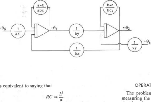
Fig. 2.-Analogue computer clrcuit, equivalent to teneral 7t-network shown in Fig, 3
OPERATIONAL ANALOGUE COMPUTER The problems of generating the driving voltage and measuring the output voltage are simpler for an opera-tional analogue computer than for a passive resistance-capacity network, because lower frequencies can be used. Figure 2 is the analogue computer circuit which is equivalent to the general z-network shown in Fig. 3. The symbols have the following meanings:
High-gain d.c. amplifier operating as an integrator €ot.: - [Zer^dt High-gain d.c. amplifi.er operating as a summer eou, - -Eein Potentiometer used as an attenuator € o u r : P . e i o P < 1 . 0
Kirchoff's law applied to the internal points 1 and 2 gives t ?
q ( R C \ : =' i l .
(13)
Fig. 3.-General r-network
and
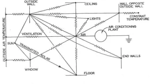
Fig. 4.-Schematic diagram for the thermal regime in a simple room with one ex-ternal wall containing a window
These can be rearmnged and integrated to give
o,
:
I (*.
u.
* **u,
- #r,), (^".)
(1s)
(16) The analogue circuit solves these equations simulta-neously, except that the time scale is different.When the integrators are used at a gain of S, the inte-gration rate is S sec- 1. The time variable for the computer is
so that one second of computer time is equal to SRC seconds of real problem time. The time scale can be speeded up by using the integrators at a faster integration rate or it can be slowed down by dividing all the poten-tiometer settings by a constant. For a homogeneous wall RC : L2 la, so
t' d, :
-t U S
(r7)
THERMAL CIRCUITS
The simple two-lump circuit representing a wall or roof can be used as a component in a larger circuit which simulates a room. To be accurate, a thermal circuit of a room must allow for heat transfer by radiation between the walls, floor and ceiling as well as by convection from these surfaces to the air. It should allow for the load due to ventilating air and any solar radiation which is trans-mitted through windows as well as that which falls on the opaque outside walls. Finally, internal heating and cooling sources must be taken into account.
Figure 4 is a schematic diagram for the thermal regime in a simple room with one external wall containing a window. It is assumed that this room is a typical module of a multi-storey building and that the wall facing the
out-e,
: I Gl,
r, *,L,
u,
- W q r(*r)
. t I t ' : . -' R C S OPPOSITE WALL CONSTANT TEMPEMTURE AIR CONDITIONING PLANT END WALLSside wall backs on a corridor which is kept at a constant temperature.
The diagram shows all of the convection coupling to the inside air but to keep the diagram clear the radiation coupling is only shown for the inside surface of the out-side wall. All of the surfaces should be radiation coupled to all the other surfaces plus the lights.
If a two-amplifier network as shown in Fig. 2 is used for the outside wall it is necessary to have an additional amplifier to obtain the surface temperature 0o. The heat balance at the outside surface is
Solar * ho(ooo - oo1 - oo -.,0t
a R (18)
Therefore
aR Solar * hoaR?oo + 0r: (l + h'aR)0, (19) so / a R \ e - - , l S o l a r + \1 + Ir,aR/ -/ h-aR \
1t'r,,"*/0"*
/ 1 \" ' (r * **)e'
(20)
by the cirpuit shown in This relationship is satisfiedFig. 5.
' l + h o a R
' l + h 1 c R
At the inside surface of this wall the heat balance sives
(Radiation from lights) *
s& :
I (0. - o_)h,_ + h"i(03 - oi) er) The first term on the right-hand side represents the
sum of all the radiation to and from the other surfaces. This can be rearranged to give
/ 1 \
(*lr, +L(h,*o,) + h"ioio* Lighrs
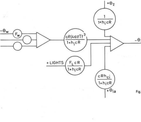
This equation is solved by the circuit in Fig. 6. F, is the overall interchange factor for radiation from the light on the wall and the Fn are the overall interchange factors for the radiation from other walls at the wall in question. Similar circuits would be required for the other sur-faces; however, the ceiling and floor can be combined since the floor of one room forms the ceiling of the room below. The two end walls are represented by one circuit since they are exactly the same in their radiation and convection coupling.
Fig. 6.-Circuit to produce inside surface temperature
This type of simulation is well suited for the types (2) and (3) problems where the plant capacity may be less than the peak loads. It is also very useful for studying the effect of different control systems since the operation of the plant in the simulated model can be controlled by a circuit with characteristics similar to the thermostat. A circuit of the sort shown, which has separate inputs for solar radiation and outside air temperature instead of a sol-air temperature is particularly useful for a study of shading devices or the orientation of a building.
This example is only intended to indicate in a general way how a thermal analogue can be used. Detailed dis-cussions on the use of thermal circuits are given in references 8, 9, 10, ll, 12 and 13.
Although the thermal circuit method takes account of heat transfer by radiation between the walls of a room, it does make some simplifying assumptions. It is assumed that the solar radiation transmitted through the window is uniformly distributed over the floor whereas it falls on a part of the floor and this exposed part is always chang-ing. Temperature gradients in the room air are ignored as are temperature variations on the surface of each wall. The non-linear effects of heat transfer by natural convec-tion can be allowed for but it is usual to use a linear approximation, i.e., a constant value of ft,. Thus, even this relatively elaborate method does not give an exact answer, but the possible error should be less than with other methods.
N U M E R I C A L M E T H O D S O F C A L C U L A T I N G TEMPERATURE DISTRIBUTION AND HEAT FLOW
If it is necessary to calculate the heat flow and temperature distribution through a single wall when the boundary conditions are not periodic, it is convenient to use a purely numerical method. The Fourier heat
: (* + tr,)0, e2)
wnere h-*.: Fw({oT3t) h i : h " i + Z h , * (23) (24)(2s)
Therefore,, : (#^),,-' (#h) Lh,-o-
+
(#h)u"*(#h)
Lights
conduction equation includes both space and time derivatives. The use of a lumped RC network or the equivalent operational analogue circuit is the same as using a finite difference approximation for the space derivatives and an exact time derivative. When the time derivative is also approximated by a difference expression it leads to a completely numerical method for calculat-ing the transient thermal behaviour of a slab.
A. The Dusinberre Method
If at any instant the temperatures 0, are known at a series of points equally spaced Ax apart through a slab, the second space derivative of temperature is
0 n + r J - 0 , - r - 2 0 ,
(26) (Ax)
Similarly if 0, is known at I and t + Lt, the time deriva-tive of temperature is
Thus equation (l) can be written as
Ln+r,t * 0n-r,t - 20^,t +\Y {r,,,*o, - 0,,r) (28) This is an explicit expression for 0n,1a6, which can be used to calculate temperatures at all points at time t + Lt, based on temperatures at time l.
ry-:LI
aLt
(.2e)
(30)
This is the equation given by Dusinberre.la
IfAx and Lt are chosen so that M : 2 this reduces to the simole Binder-Schmidt formula
on,t+Lt:t--+L"
M
N o0oo,, + 0 t,t + i 0,,, - o,
(3 1)
Two is the smallest value of M which will give a stable solution. In general the accuracy of a numerical solution is improved if Ax or Al is reduced since then the approxi-mations for the derivatives are more accurate. The stability requirement that M 2 2 means Ax can only be reduced if Al is also reduced.
The Dusinberre equation can be used for all the in-ternal points in a slab. At the surfaces the heat transfer may be by convection, in which case a heat balance gives
- o' ') * L4{ (o"t
- 0""-o'\
h o ( | o o . , - oo.,):; ( 0 , , , - ,,,, . a . 2 \ a , I h^Lx When .- : N, this simplifies to (32) (33) 9 o . t :N"+1++
This can be used to calculate the slab surface tempera-ture at time, t, when the air temperatempera-ture and the tempera-ture at the fust internal point are known at r and the surface temperature is known at t - Lt.
This differs from the expression given by Dusinberrera because it is based on the backward rather than forward approximation of the time derivative at the surface. This is advantageous because it eliminates any special stability criterion for the case with a convection boundary condition.
These simple arithmetic operations are well suited for calculation with an automatic digital computer. The high speed of the computer makes it practical to use small values of Al and Ax and so obtain precise values of the temperatures. This approach is particularly useful when the temperature distribution through the slab is the main point of interest whereas the analogue methods are most useful if only heat flow across the surfaces are wanted. B. The Liebmann Method
If instead of a forward approximation of the time derivative the backward approximation is used,
(f),,*
0 n , t - l Q n , t - t t(3s)
Equation (1) becomes
0 , * 1 , , l0 r - 1 - (2 + M)0,.,
: -9r,t- yt (36)
A similar equation can be written for each internal point. This set of equations must be solved simultaneously for the 0,., knowing the 0n.r-or.
The chief advantage of this method is that the solutions are stable for all values of M so that Ax and Ar can be varied independently. When the rates of change of tem-perature are small large values of At can be used and thus the work necessary to obtain a solution is very much less than with the standard finite difference method. However, there is the difficulty that a series of equations must be solved simultaneously. Liebmann1s.16 pointed out that a simple all resistance network could be used to solve these simultaneous algebraic equations.
Kirchoff's law applied to a typical nodal point in Fig. 7 gives vn_ r.t - vn.t . vn+ t.t - 4., . vr.t_ tt - vr.f --:---:-::--- 1 "- -' "'l - 6 /a1\ R, R* R, S O vn- t ,t * vn* t,, - 2Vn,r : ! {r,,, - Vn,t- u) (38) r\o (34)
(y),.
(21) L t If 9 n + r , t * 0 n - r , t - ( 2 - M ) 0 , , t 0n,t+ Lr M M R" R o Thus if : M(3e
)
Fig. 7.-Resistance network of the Liebmann type.for internal points
the voltages at the nodal points of this network will be equal to the temperatures in a homogeneous slab at time I if voltages equal to the temperatures at t - Lt are applied at the open ends of the resistors Ro.
The apparatus described by Leibmann had, in addition to a comb network, two potentiometers for each nodal point. They were arranged so that one potentiometer of each pair would supply the voltages Yn.t- at to the open end of the R, resistors and the other measure the voltages 2",, which appeared at the nodal points. When the po-tentiometers measuring the nodal point voltages are all balanced, they can be interchanged with the set which are connected to Ro. Each time the potentiometers are interchanged the solution is advanced by At. With this apparatus the solution of a transient heat-flow problem requires only the simple repetitive operation of balancing a potentiometer and recording the setting.
If ambient air temperature and surface film conduc-tance are known rather than slab surface temperature, an extra unit is added to the circuit so that the surface temperature can also be found. Figure 8 shows the circuit for a convection boundary condition.
With this type of analogue, the unknown temperatures can be measured easily and accurately by a potentiometer method because the voltages are steady. Another very useful result of the step-by-step progression in time is that the circuit parameters can be varied during the course of a problem to allow for non linearities such as film conductances which depend on the temperature drop across the film, or thermal properties which are functions of temperature. The driving temperature need only be defined as a table of values at various times. This is very much simpler than having to have a signal generator which will give a particular temperature-time relationship.
R 1 N o
1 2 3 4 r , " 3 i
7 8 s
Fig. 9,-Heat flow across inside surface of a wall caused by a square pulse variation of the outside air temperature
C. Response Factor Method
The assumption that the differential equation describ-ing the heat flow through a wall is linear allows the superposition of solutions. Thus the temperature or heat flow at any point in a wall which obtains for some arbitrary driving temperature cycle can be calculated simply. It is only necessary to know the response (i.e. the temperature or heat flow at the point of interest) to a unit pulse variation in the driving temperature for the same boundary conditions, since the arbitrary input can be approximated by a succession ofpulses and the effects of these pulses can be added to give the total response at any time. The application of this method to heating and cooling load design calculations was first suggested by Brisken and Reque17. This approach, with a rect-angular pulse, is equivalent to using Duhamel's theorem and doing the integration by taking mean values over an interval equal to the pulse duration. The shorter the time interval used, the closer the calculated answer will approach the exact solution. If the driving temperature is represented by a sequence of overlapping triangular pulses it is equivalent to trapezoidal integration of Duhamel's integral.
The heat flow across the inside surface of a wall due to a square and triangle pulse variations of the outside air temperature are shown in Figs. 9 and 10. The response can also be represented by a series of numbers which are the ordinates of the response curve at times 1, 2,3...
1 . 0 0
T I M E - - }
Fig. 10.-Heat flow across inside surface of a wall caused by a triangle pulse variation of the outside air temperature
DRIVING U R E G HEAT FLOW N 15 16
q
,>r
These are called the response factors. The heat flow at any time I is simply
e t : Q t t r * 0 r - g 2 1 - 0 r - 2 r 3 * . . . (40)
where 0r, 9t-r, 0t-2,... are the values of the driving temperature at intervals equal to half the duration of the triangle pulse, starting at t, and going backward in time. The response factors for a wall can be determined by experiment if a large-scale heat-flow apparatus is avail-able. Such an apparatus is described by SolvasonlE. Simultaneous observations of driving temperature and the resulting heat flow can be used to form a set of simultaneous algebraic equations where the response factors are the unknowns.,
In matrix notation
(41)
Thus
["] : [0] -' . [q] (42)
Response factors can be obtained by this experimental method for walls where the heat flow is not strictly one dimensional, e.g., walls with insulation in the stud spaces or walls made of hollow concrete blocks. Some forms of temperature variation are much more suitable for this type of test than others because they give a simple inverse matrix. A periodic temperature variation is very poor but a uniform rate of temperature change from one steady state to another is quite satisfactory. The fact that the sum of the response factors must equal the U value is a useful check on an experimentally determined set of response factors.
The response factor approach has been extended to problems where the film conductance is also a variable with timele but it cannot be applied to the non-linear problem where film conductance depends on temperature difference.
If the temperature of the inside air is not constant it can be allowed for by using a second set of factors which relate heat flow across the inside surface of the wall to a pulse step in the inside air temperature. This is a straight-forward procedure but it effectively doubles the work involved in a calculation.
The response factor method uses assumption (4) and hence may give wrong results if the surface of the wall 'sees' other surfaces at temperatures much different from the air temperature. For well-insulated walls where the inside film resistance is only a small part of the total wall resistance this is a convenient method for finding the heat flux at a particular time knowing only the wall characteristics and the driving temperature for a pre-ceding period equal to the response time of the wall.
coNcLUstoNs
This summary of the methods available for calcnlating heat flow and temperature distribution through walls indicates that accurate calculations are possible. How. ever, more information on weather conditions and the thermal performance characteristics of building com-ponents is needed. The previous discussion suggests that a tabulation of the two-lump circuits, which are equiva-lent to the common wall and roof sections, would be very desirable. These could be used directly for a thermal circuit representation of the walls and the other quantities such as matrix coefficients and response factors can be derived easily when needed.
The weather data should include hourly average values of outside air temperature and humidity, total solar radiation on a horizontal surface with the percentage of the total due to diffuse sky radiation, and wind direction and velocity. For most design procedures these weather factors are combined to give a sol-air temperature but this also depends on the surface emissivity and orienta-tion. Thus it seems more appropriate to publish the weather data in separate form and let the designer com-bine them to obtain the sol-air temperature fof a particular situation.
Economic studies, which require accurate estimates of operating costs, need continuous weather records for a season. The less elaborate design procedures need only data for a day which can be expected to occur once every five or ten years; and for days which will be exceeded on average 2,5, ot l0 times in any season.
The equivalent temperature difference method is by far the simplest way to calculate the heat flow through the outer shell of a building. Only for large projects where the economics of shading or orientation are to be studied is it feasible to use a thermal circuit directly for design calculations. More accurate load estimation can be achieved by using a thermal circuit analogue to determine equivalent temperature differences for the common types of construction using the various weather data mentioned above. These results could then be used with more confidence and smaller safety margins.
ACKNOWLEDGMENTS
The author wishes to acknowledge the assistance he obtained by many discussions of the various methods with Mr. G. Starke. It was through these discussions that the merits and limitations of each technique became clear. This paper is a contribution from the Division of Building Research, National Research Council of Canada and is published with the approval of the Director of the Division.
REFERENCES
l. A S.E.A.E. Guide, 1959. Chapter on cooling load.
2. M.lcruv, C. O. and Wnrcnr, L. T. Periodic heat flow, homo-geneous walls or roofs. A.S.H.V.E. Transactions, 1944, 50, 293.
1"",
l':
3. M^rcrrv, C. O. and Wnrcnr, L. T. Periodic heat flow, com-posite walls or roofs. A.S.H.V.E. Transactions, 1946, 52,
282.
4. Gnour.uwnrnn, I. S. Solar radiation in air conditioning. Pub-lished by Crosby Lockwood & Sons, Ltd., London, 195?. 5. hpns, L. A. Matrix analysis of heat transfer problems. Journal
of the Franklin Institute, 1957, 263, (3), 195.
6. MuNcrv, R. W. The calcrrlation of temperatures inside build-ings having variable external conditions. Ausftalian Journal of Applied Science, 1953,4, (2), 189.
7. SrtpnnNsoN, D. G. and STARKE, G. O. Desigrr of a z network for heat flow analog. Journal of,AppliBd Mechanics,1959, 2.6, (2),3@.
8. Bucnsrnc, H. Cooling load from thermal network solutions. A.S.E.A.E. Transactions, 1958, 64, lll.
9. P.rrucr.ne, G. V., V.lNcn, P. and CBnNny, A. N. Analysis of an air-conditioning thermal circuit by an electronic differential atalyzer. A.S.H.A.E. Transactions, 1957, 63, 129.
10. Bucnnrnc, H. Electric analog studies of single walls. A.S.H.A.E. Transactions, 1956, 62, 177.
I l. Norrncr, H. B. and ParulELEE, G. V. Circuit analysis applied to load estimating. A.S.H.A.E. Transactions, 1954, ffi,59.
NorrAGE, H. B. and PARMELEE, G. V. Circuit analysis applied to load estimating, Part ll-Influence of transmitted solar radiation. A.S.H.A.E. Transactions, 1955, 61, 125. Wrr,Lcox, et al. Aaalogcomputer analysis of residential cooling
loads. A. S, H. A. E. Transact ions, 19 54, 60, 505.
DusrNnrnnr, G. M. Numerical analysis of heat flow. Published by McGraw-Hill, 1949.
LrnsMANN, G. A new electrical analog method for the solution of transient heat conduction problems. A.S,M.E. Trans-actians, 1956,78, (3), 655.
LTEBMANN, G. Solution of transient heat transfer problems by the resistance network analog method. A.S.M.E. Trans-actions, 1956,78, (6), 1267 .
BRTsKEN, W. R. and Rrqw, S. G. Hqat load calculation by thermal response. A.S.H.A.E. Transactions, 1956, 62, 39t. Sor,vlsow, K. R. Large-scale wall heat-flow measuring appara-tus. Presented at the A.S.H.R.A.E. Antual Meeting, June 1959.
Itll, P. R. A method of computing the transient temperature of thick walls from arbitrary variation of adiabatic wall temperature and heat-transfer coefficient, NACA, TN 4105, Oct. 1957. 12. 1 3 . 14. 1 5 . 1 7 . 1 8 . 1 6 . 1 9 . l0
A l i s t o f a l l p u b l i c a t i o n s of the Division o f B u i l d i n g Research ie available and may be ob-t a i n e d f r o m ob-the Publicaob-tions Secob-tion, Division of B u i l d i n g R e s e a r c h , National Research Council, O t t a w a , Canada.