CubeSat Attitude Control using Micronewton
Electrospray Thruster Actuation
by
Mark David Van de Loo
S.B., Aerospace Engineering with Information Technology, Massachusetts
Institute of Technology (2013)
Submitted to the Department of Aeronautics and Astronautics
in partial fulfillment of the requirements for the degree of
Master of Science in Aeronautics and Astronautics
at the
MASSACHUSETTS INSTITUTE OF TECHNOLOGY
June 2014
ARCHIVES
MASSACHUSETTS INBITITE OF TECHNOLOGYJUN 16
201
LIBRARIES
@
Massachusetts Institute of Technology 2014. All rights reserved.
Signature redacted
A u th or ...
Department of Aeronautics and Astronautics
May 9, 2014
Certified by ...
Signature redacted
Sara Seager
Class of 1941 Professor of Physics and Planetary Science
Thesis Supervisor
Signature redacted
A ccepted by ...
CubeSat Attitude Control using Micronewton Electrospray
Thruster Actuation
by
Mark David Van de Loo
Submitted to the Department of Aeronautics and Astronautics on May 9, 2014, in partial fulfillment of the
requirements for the degree of
Master of Science in Aeronautics and Astronautics
Abstract
Micronewton electrospray thrusters are a promising new actuator for CubeSat attitude con-trol. Electrospray thrusters have advantages over current state of the art CubeSat attitude actuators in mass, volume, and their ability to produce translational acceleration in addi-tion to control moments. An attitude determinaaddi-tion and control system was designed for a
1U CubeSat assuming commercial-off-the-shelf attitude determination hardware components
and six electrospray thrusters developed by the MIT Space Propulsion Laboratory. A high fidelity spacecraft dynamics simulation was constructed for analysis of the performance of the ADCS system. Attitude determination was tested with an engineering model of a 1U CubeSat, and the entire ADCS system was tested in simulation. Results of these preliminary tests show the use of electrospray thrusters as attitude actuators to be feasible, although significant work remains to complete a flight-ready ADCS system.
Thesis Supervisor: Sara Seager
Title: Class of 1941 Professor of Physics and Planetary Science Academic Advisor: Paulo C. Lozano
Acknowledgments
There are many people I want to thank who have made the completion of this thesis
possi-ble. To Professor Sara Seager who has inspired me to dream and given me the opportunity to work on intriguing problems. To Professor Paulo Lozano for his invaluable advice and
support throughout my time at MIT. To my TSat teammates Mary Knapp, Akshata Krish-namurthy, and Fernando Mier Hicks who made TSat engineering model testing a reality. To
the Nexterra foundation for their generous sponsorship of the TSat project. To Alessandra Babuscia, Chris Pong, Ian Sugel, Josh Joseph, Justin Smith, Lars Blackmore, and Carolyn
Major for their mentorship and life advice. To Marie Stuppard and Beth Marois who are two
of the most helpful people I know. To my roommate Mitch Westwood for his constant en-couragement and motivation. To Professor Sheila Widnall for her wisdom and overwhelming support, and to Bill Widnall for his inspiration and many great days of sailing in
Marble-head. To Maggie McConnell who always helps me to see what is important in life. And finally, to my dad Dave, my mom Sue, my sisters Kate and Meg, and my brother Luke who
Contents
List of Figures 10
List of Tables 17
1 Introduction 19
1.1 CubeSats: A Developing Platform for Space Exploration . . . . 19
1.1.1 The CubeSat Standard . . . . 19
1.1.2 Current CubeSat Mission Limitations . . . . 20
1.1.3 Motivation for Microthruster Actuation in CubeSat Attitude Control 22 1.1.4 Proposed CubeSat Missions Requiring Microthruster Actuation . . . 23
1.2 Electrospray: A Microthruster Technology . . . . 25
1.2.1 Principles of Electrospray Thrusters . . . . 25
1.2.2 Electrospray Thrusters as CubeSat Actuators . . . . 27
1.2.3 Comparison to Current State of the Art CubeSat Attitude Actuators 29 1.3 TSat: A Demonstration Mission for Electrospray Thrusters . . . . 32
1.3.1 M ission Overview . . . . 32
1.3.2 Spacecraft Subsystems . . . . 33
1.3.3 Preflight Testing . . . . 33
1.3.4 Electrospray Thruster Attitude Control . . . . 35
2 System Hardware 36 2.1 Attitude Determination Sensors . . . . 36
2.1.1 3-Axis Magnetometer . . . . 37
2.1.2 Photodiode Sun Sensors . . . . 38
2.1.3 MEMS 1-axis Gyros . . . . 41
2.1.4 GPS Receiver . . . . 42
2.2 Electrospray Microthruster Actuators . . . . 43
2.2.1 Thruster Configuration . . . . 43
2.2.2 Fundamentals of Operation . . . . 45
2.2.3 Propulsion Power Unit . . . . 47
2.2.4 Performance Characteristics . . . . 50
3 System Software 53 3.1 Software Overview . . . . 54
3.1.1 Coordinate Systems and Labels . . . . 54
3.1.2 Flight Software State Variable Structure . . . . 58
3.2 Sensor Processing . . . . 58
3.2.1 Sun Sensor Processing . . . . 58
3.2.2 Gyro Processing . . . . 59
3.3 Attitude Determination . . . . 60
3.3.1 Attitude Measurement . . . . 61
3.3.2 Attitude Estimator . . . . 61
3.4 Guidance . . . . 62
3.4.1 Ground Command Processing . . . . 63
3.5 Attitude Control Law . . . . 64
3.5.1 Torque Command . . . . 64
3.6 Actuator Command Preparation . . . . 65
3.6.1 Thrust Allocation . . . . 65
4 High Fidelity Simulation (TSATsim) 68 4.1 Structure of the Simulation . . . . 68
4.1.1 Flight Software Side . . . . 70
4.1.2 Truth Side . . . . 71
4.2 Simulation of Attitude Determination Hardware . . . . 71
4.2.1 G yros . . . . 72
4.2.2 Sun Sensors . . . . 74
4.2.3 Magnetometer . . . . 74
4.3 Simulation of Attitude Control Hardware . . . . 75
4.3.1 Electrospray Thrusters . . . . 76
4.4 Simulation of Dynamics and the Space Environment . . . . 77
4.4.1 Runge-Kutta Integrator . . . . 78 4.4.2 G ravity . . . . 79 4.4.3 Aerodynamic Drag . . . . 80 4.4.4 Geomagnetic Field . . . . 80 4.4.5 Sun Position . . . . 81 4.5 Simulation Results . . . . 82
4.5.1 Truth Environment Data . . . . 83
4.5.2 Attitude Determination Performance . . . . 87
4.5.3 Attitude Control Performance . . . . 89
5 TSat 1-Degree of Freedom Testbed 96 5.1 Testbed Implementation . . . . 96
5.1.1 Magnetic Levitation Balance . . . . 97
5.1.2 TSat Engineering Model . . . . 98
5.1.3 Flight Software Implementation . . . . 99
5.1.4 Testbed Environment . . . 101
5.2 Attitude Determination Test . . . 102
5.2.1 Test Description . . . 103
5.2.2 Test Results . . . 103
5.3 Future Testing . . . 107
5.3.1 Rate Nulling . . . 108
5.3.2 Angle Command Slew . . . 108
5.3.3 Rate Command Slew . . . 108
5.3.4 Sun racking . . . 109
6 Future Work and Conclusion 110 6.1 Software Improvements . . . . 110
6.1.1 Handling of Anomalies . . . 111
6.1.2 Sensor Processing . . . . 112
6.1.3 GPS Processing . . . . 114
6.1.4 Attitude Determination Filter . . . 114
6.1.5 Attitude Control Law . . . . 115
6.2 Hardware Improvements . . . 116 6.3 Model Improvements . . . . 116 6.3.1 Sensor Models . . . . 116 6.3.2 Actuator Models . . . 117 6.3.3 Environmental Dynamics . . . . 117 6.4 Further Testing . . . . 117
6.4.1 1-DOF Levitation Testbed . . . . 118
6.4.2 Flight Demonstration . . . 119
6.5 Conclusion . . . . 122
A Flight Software Algorithm Pseudocode and Implementation for Analysis 123 A.1 FSW Master . . . 123
A.1.1 Pseudocode for tsat-gnc . . . . 123
A.1.2 TSATsim implementation of tsat-gnc . . . . 124
A.2 Sensor Processing . . . 125
A.2.2 TSATsim implementation of gnc-sensor-processing
A.2.3 Inputs and Outputs of gnc-process-ss . . . . 126
A.2.4 Pseudocode for gnc-process-ss . . . . 128
A.2.5 TSATsim implementation of gnc-process-ss . . . . 129
A.2.6 Inputs and Outputs of gnc-process-gyro . . . . 133
A.2.7 Pseudocode for gnc-process-gyro . . . . 134
A.2.8 TSATsim implementation of gnc.process.-gyro . . . . 134
A.3 Attitude Determination . . . . 135
A.3.1 Pseudocode for gnc-attitude-determination . . . 135
A.3.2 TSATsim implementation of gnc-attitude-determination . . . 136
A.3.3 Inputs and Outputs of gnc-TRIAD . . . . 137
A.3.4 Pseudocode for gncTRIAD . . . . 141
A.3.5 TSATsim Implementation of gncTRIAD . . . . 148
A.3.6 Inputs and Outputs of gnc-attitude-kf . . . . 157
A.3.7 Pseudocode for gnc-attitude-kf . . . . 160
A.3.8 TSATsim Implementation of gnc-attitude-kf . . . . 167
A .4 G uidance . . . . 179
A.4.1 Pseudocode for gnc-guidance . . . . 179
A.4.2 TSATsim implementation of gnc.guidance . . . . 180
A.4.3 Inputs and Outputs of fsw-gnd-cmd . . . . 181
A.4.4 Pseudocode for fsw-gnd-cmd . . . 182
A.4.5 TSATsim Implementation of fsw-gnd-cmd . . . . 182
A.5 Attitude Control Law . . . . 184
A.5.1 Pseudocode for gnc-attitude-cl . . . . 184
A.5.2 TSATsim implementation of gnc-attitudecl . . . . 184
A.5.3 Inputs and Outputs of gncitorque-cmd . . . . 185
A.5.4 Pseudocode for gncitorque-cmd . . . . 187
A.5.5 TSATsim Implementation of gnc-torque-cmd . . . . 188
A.6 Command Preparation ...
A.6.1 Pseudocode for gnc-cmdprep . . . .
A.6.2 TSATsim implementation of gnc-cmd-prep . . A.6.3 Inputs and Outputs of gnc-thrust-alloc . . . .
A.6.4 Pseudocode for gnc-thrust-alloc . . . .
A.6.5 TSATsim Implementation of gncithrust-alloc A.7 ADCS Flight Software Initialization . . . . A.7.1 Listing of readxfswcmd (from TSATsim) . . . A.7.2 Sample fswcmd file . . . . A.8 FSW State Variable Data Structure . . . .
B Simulation Truth State Data Structure
References . . . . 191 . . . . 191 . . . 192 . . . 193 . . . 195 . . . . 198 . . . . 202 . . . 202 . . . 205 . . . 205 210 215
List of Figures
1-1 1U CubeSat with deployed antennas. (credit: Mary Knapp) . . . . 20
1-2 P-POD CubeSat Deployer [26]. . . . . 20
1-3 Drawing of an electrospray thruster assembly [4]. . . . . 25
1-4 Two assembled iEPS thruster modules [11]. . . . . 28
1-5 Scanning electron microscope image of a porous emitter array [4]. . . . . 29
1-6 MAI-201 CubeSat reaction wheel assembly [12]. . . . . 30
1-7 NanoPower solar panel [5]. . . . . 31
1-8 CAD drawing of the SPL magnetic levitation balance. (credit: Fernando Mier H icks). . . . . 34
2-1 Honeywell HMC5843 magnetometer (credit: Honeywell). . . . . 37
2-2 Magnitude of the magnetic field experienced by TSat over one orbital period as calculated by the TSat GNC simulation. The simulated orbit is similar to the orbit of the International Space Station. . . . . 38
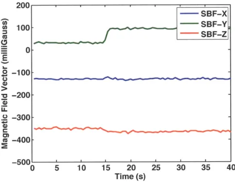
2-3 Sample magnetometer output when subjected to the geomagnetic field in the lab and rotated through 180 degrees. . . . . 39
2-4 Sample output of two photodiode Sun sensors when rotated past a light source. The bias value of approximately 12 mV is attributed to ambient light in the lab and reflection of the light source. . . . . 40
2-5 Sun sensor test setup used to record the data given in Figure 2-4. . . . . 41
2-7 Sample output of an ADIS 16251 gyro. . . . . 42
2-8 Surrey SGR-05U GPS receiver [9]. . . . . 43
2-9 Conceptual illustration of two thrusters that produce a control moment on
the spacecraft with zero net force. (credit: Akshata Krishnamurthy) ... 44 2-10 Summary of the thruster configuration trade study. Three-axis attitude
con-trol, with control about one axis that produces no net force on the spacecraft is possible using eight thrusters. Additionally, the number of custom built
solar panels required for each thruster configuration was determined. The implications of the number of custom built solar panels are beyond the scope of this document. (credit: Akshata Krishnamurthy) . . . . 45 2-11 TSat six-thruster configuration provides control moments about any
rota-tional axis. . . . . 46
2-12 Drawing of a porous emitter tip showing the formation of a Taylor cone and
extraction of ions from the ionic liquid. (Credit: MIT SPL) . . . . 47
2-13 Conceptual sketch showing eight iEPS thrusters mounted on top of a stack of
three Espace PPU electronics boards [11]. . . . . 49 2-14 Sample I-V characteristics of several thrusters. Efficient thrusters such as
Boro 45 have steep I-V curves, and reach high current levels at the maximum driving voltage. Less efficient thrusters such as Boro 37 have shallower I-V
curves, and do not reach the same high currents at the maximum driving voltage. Since current is a continuous function of the driving voltage, there
is no theoretical minimum thrust value. The measured I-V curves of the thrusters used for flight will be programmed into the PPU interface algorithm to convert thruster commands from the ADCS software into driving voltages.
(credit: Fernando Mier Hicks) . . . . 52
3-1 Structure of simulated software. . . . . 55 3-2 TSat Spacecraft Body Frame showing thrusters in the testbed configuration. 56 3-3 TSat spacecraft faces . . . . 57
3-4 Thruster numbering. . . . . 57
3-5 Context of the sensor processing task. Sensor processing is the first task called in each control cycle. It processes raw data from the Sun sensors and gyros, preparing inputs for the attitude determination task. . . . . 59 3-6 Context of the attitude determination task. Attitude determination runs
im-mediately after sensor processing. It incorporates the processed measurements from ADCS sensors with propagated estimates to compute an estimated at-titude quaternion and body rates. . . . . 60
3-7 Context of the guidance task. Guidance uses the spacecraft state estimated by
attitude determination to decide the desired behavior of the satellite. Ground
commands and the spacecraft mode of operation are also incorporated in this decision . . . . 63
3-8 Context of the attitude control law task. The attitude control law takes in the estimated attitude and body rates from the attitude determination task, and the commanded attitude and body rates from the guidance task. It then
computes the actuator torque that will move the spacecraft to the commanded state from the current state. . . . . 64
3-9 Context of the actuator command preparation task. Command preparation allocates the commanded torque from the control law to the appropriate
actu-ators. Actuator commands are computed and sent to the actuators to impart control moments on the spacecraft. . . . . 66
4-1 Structure of TSATsim. The "Simulation" block represents the main
simu-lation loop, which calls all of the other blocks in order at each simusimu-lation timestep. The "Run Flight Software" block represents the simulated ADCS
flight software or "flight software side" of the simulation, while all of the other
4-2 Context of TSATsim sensor models. The "Update Sensors" wrapper calls the gyro, Sun sensor, and magnetometer models, and their outputs are written to the truth state data structure. .... . ... .. . . . .. .. . . . .. . . .. 72
4-3 Sample output of a simulated gyro. At a time of 100 seconds, a moment is applied about the positive axis of rotation of the gyro for a duration of approximately 30 seconds. A moment is then applied in the opposite direction until the rate of rotation is close to zero. . . . . 73
4-4 Sample output of a simulated Sun sensor. The sensor begins facing the Sun, and is then rotated away. . . . . 75
4-5 Sample output of a simulated magnetometer. Slow variation is observed as the magnetometer moves in an orbit around the Earth. . . . . 76
4-6 Context of TSATsim actuator models. The actuator models are updated based on commands from the simulated flight software. . . . . 77
4-7 Context of TSATsim space environment models. Environment models are updated for each intermediate state of the four-stage Runge-Kutta integration. 78 4-8 Elements of the unit vector in the direction of the Sun relative to the
Space-craft Body Frame origin. On the time scale of the simulation, the position of the Sun relative to the spacecraft may be treated as fixed, so this plot illustrates a 90-degree rotation of the spacecraft about the positive SBF-Z axis. 83 4-9 Elements of the unit vector in the direction of the Sun relative to the SBF
origin for the duration of the slew maneuver. . . . . 84 4-10 TSATsim Boolean eclipse flag. This flag is equal to 0 during orbit day and 1
during orbit night. . . . . 85
4-11 Inertial position of the spacecraft relative to the center of the Earth in the
ECI frame. The simulated orbit is similar to the orbit of the International
4-12 Inertial velocity of the spacecraft relative to the center of the Earth in the
ECI frame. The simulated orbit is similar to the orbit of the International
Space Station with the orbital elements given in Table 4.2. . . . . 86
4-13 Attitude determination error. Computed as the smallest angle of rotation between the truth attitude and the flight software attitude estimate. The
error is on the order of 1 degree for the entire simulation, which is acceptable for most CubeSat missions. The linear increase in error during the second half
of the simulation is caused by a lack of attitude measurements during orbit
n igh t. . . . . 87
4-14 Body rate determination error. Computed as the difference between the flight software estimated body rates and the truth body rates. The error is less than
0.01 deg/sec, which is acceptable for most CubeSat missions. . . . . 88
4-15 Trace of the Unscented Kalman Filter covariance. The covariance grows
dur-ing orbit night, representdur-ing a growdur-ing uncertainty in the attitude estimate
due to the lack of a recent attitude measurement. . . . . 89
4-16 Attitude error angle. A sharp increase in attitude error is observed when a
new attitude quaternion is commanded to initiate the slew maneuver. The attitude error returns toward zero as the maneuver is completed. . . . . 90
4-17 Attitude error angle during the steady state portion of the simulation after
the slew maneuver is complete. In steady state, the attitude error is less than two degrees, which is acceptable for most CubeSat missions. The attitude
error grows linearly during orbit night, as a result of the growing attitude determination error during that time. . . . . 91
4-18 Body rate error increases during the slew maneuver, since zero body rates
are commanded but the spacecraft must rotate in order to reach a new com-manded attitude. Body rate error settles back toward zero as the slew
4-19 Body rate error during the steady state portion of the simulation after the slew maneuver is complete. In steady state, the body rate error remains within
±0.00025 radians per second, which is acceptable for most CubeSat missions. 92
4-20 Torque command from the flight software attitude control law. A large torque is commanded about the positive SBF-Z axis to initiate the slew maneuver. 93
4-21 Thruster commands. Thrusters 1 and 3 are saturated to begin the rotation for the slew maneuver. Thrusters 0 and 2 are commanded to high values to slow the rate of rotation as the spacecraft reaches the new commanded attitude. 93 4-22 Flight software commanded attitude quaternion. A new quaternion command
is sent to the spacecraft at a simulation time of 300 seconds to initiate the slew m aneuver. . . . . 94 4-23 Actual attitude quaternion from the truth side model. The actual attitude
quaternion converges to the commanded attitude quaternion. . . . . 94 4-24 Flight software commanded body rates. Commanded body rates are zero
throughout the simulation. . . . . 95
4-25 Actual body rates from the truth side model. Truth body rates are nonzero between 300 and 600 seconds to allow rotation to a new commanded attitude, but then converge to the commanded body rates. . . . . 95 5-1 Illustration of the magnetic levitation balance laser sensing system. Lasers
sense vertical displacement of the CubeSat engineering model and measure-ments are fed back to a control law that levitates the model by varying the strength of an electromagnet. (credit: Fernando Mier Hicks) . . . . 98 5-2 Plate attached to the bottom face of the engineering model to aid in the
measurement of the angle of rotation by the levitation balance. Angular encoder software detects the colored circles to measure the angle of rotation of the engineering model. . . . . 99
5-3 Interior of the TSat engineering model. Solar panels have been removed for
interior access. The upper board contains the NanoMind flight computer and a memory card for data logging. NanoPower batteries are attached to the
low er board. . . . . 100
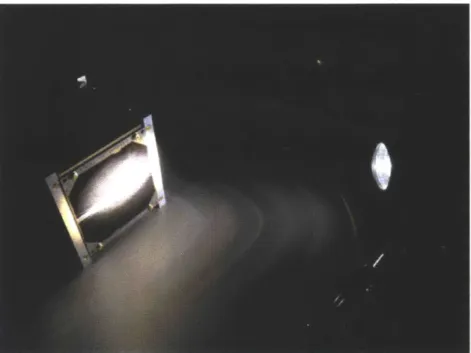
5-4 TSat engineering model levitated by the magnetic levitation balance. . . . . 101 5-5 Darkroom testbed setup for preliminary attitude determination testing. The
Sun source flashlight is visible on the right of the figure, and the TSat
engi-neering model with solar panels removed for internal access is on the left. . . 102
5-6 Attitude determination error. Calculated as the minimum angle between the
estimated and truth attitude. Attitude determination error converges to zero in approximately 100 seconds. . . . . 104
5-7 Body rate determination error. Calculated as the difference between the
es-timated and true spacecraft body rates. The body rate determination error
converges to zero in approximately 100 seconds. . . . . 104
5-8 Attitude quaternion estimated by the TSat engineering model. The estimated
attitude converges to the true attitude shown in Figure 5-9. . . . . 105 5-9 True attitude quaternion. The true attitude remains constant throughout the
test. . .. . . .. ... ... .... ... .. .... . . . .. . . 105 5-10 Reflection of light by the aluminum edges of the TSat engineering model
struc-ture. Reflections are thought to cause inaccuracies in Sun sensor measurements. 107
6-1 TSat flight demonstration tests and corresponding objectives. The flight demonstration tests will prove the ability of electrospray thrusters as CubeSat actuators by addressing objectives 3 and 4 on the left of the figure. (credit:
List of Tables
1.1 Summary of characteristics of propulsion technologies available for small space-craft compiled from
[13].
The main advantages of electrospray thrusters in-clude high efficiency and the absence of pressure vessels and volatilepropel-lants. The main disadvantage of electrospray thrusters is the high driving voltage required for operation. (credit: MIT Seager Group INVEST proposal) 27
1.2 Comparison of CubeSat attitude actuators. . . . . 30 3.1 GNC coordinate systems. . . . . 56
4.1 Summary of commands sent to the spacecraft during the 90-degree slew sim-ulation. Commanded values remain active indefinitely unless they are
over-written by another call to the same command. . . . . 82
4.2 Summary of the orbit used for the 90-degree slew simulation. The orbital
elements in this table are the orbital elements of the spacecraft upon initial-ization of the simulation (at simulation time 0.0). . . . . 82 6.1 Summary of attitude control testing on the 1-DOF Levitation Testbed in the
Astrovac vacuum chamber. Tests are designed to resemble common on-orbit maneuvers and to verify the performance of the TSat attitude determination
6.2 Description of TSat flight demonstration tests. Tests will be executed in
order of increasing "difficulty," beginning with open loop testing to measure the performance of the electrospray thrusters, and continuing with closed loop
testing to demonstrate the capabilities of the complete attitude determination and control system . . . . . 121
Chapter 1
Introduction
1.1
CubeSats: A Developing Platform for Space
Ex-ploration
1.1.1
The CubeSat Standard
A CubeSat is a type of satellite that meets design specifications developed by California
Polytechnic State University in San Louis Obispo and the Space Systems Development Lab at Stanford University [18]. The CubeSat standard was developed with the intent of
mak-ing space more accessible to small payloads. This is accomplished both by allowmak-ing faster development of small satellite missions through the creation of standardized commercial-off-the-shelf (COTS) components, and by streamlining the launch process as a secondary payload on a large launch vehicle [26]. The CubeSat specification requires that a "1U" CubeSat have external dimensions of 10 cm x 10 cm x 10 cm, and a maximum mass of 1.33
kg. A computer drawing of a 1U CubeSat is shown in Figure 1-1.
Two or three "1U" volumes may be fixed together to form a "2U" or "3U" CubeSat
[26]. In the near future, a revised CubeSat specification will also include "6U" and possibly
even "12U" options [25]. CubeSats are commonly deployed from a spring-loaded "P-POD" (PicoSatellite Orbital Deployer) attached to a launch vehicle aft of its primary payload, or
Figure 1-1: 1U CubeSat with deployed antennas. (credit: Mary Knapp)
from a JAXA deployer attached to the Japanese robotic arm of the International Space
Station [26]. The P-POD deployer is shown in figure 1-2.
Figure 1-2: P-POD CubeSat Deployer [26].
1.1.2
Current CubeSat Mission Limitations
Over the last decade and a half, many academic institutions have developed CubeSats as
educational tools and technology demonstration platforms. The low mission cost, usually less than $200,000 makes flight experience attainable in educational situations where it would not
be with larger spacecraft. In addition, large organizations including NASA, The Aerospace Corporation, and Boeing have begun to explore the potential of CubeSats as a platform for science and commercial technology [3]. As of August 2013, 53 CubeSats were on orbit and actively tracked by the North American Aerospace Defense Command (NORAD), and more than 66 additional CubeSats were awaiting a launch opportunity as reported through the
NASA CubeSat Launch Initiative [25].
As CubeSat platforms have come under consideration for Earth observation, atmospheric
science, and astronomy, fundamental limitations due to weaknesses in the areas of CubeSat attitude control and translational ability have been recognized. Attitude control refers to
control of the orientation and rotational rates of a satellite about its center of mass, while translation refers to maneuvers involving an acceleration of the satellite's center of mass. Nanosatellite propulsion technology is largely unproven, and there are no commercially avail-able flight-demonstrated propulsion solutions availavail-able for CubeSats [3]. Without a proven and readily available propulsion system, CubeSat missions requiring formation flight or preci-sion constellations are not possible. Possible objectives of interplanetary and asteroid science missions are limited by the absence of translational control, and the inability to compensate for atmospheric drag forces places limits on the minimum operating altitude and the mission lifetime of CubeSats in low Earth orbit. Though nanosatellite attitude control systems are more advanced than their translational control counterparts, a majority of nanosatellites are still designed without active attitude control [3]. Many are passively controlled using mag-netorquers that interact with the geomagnetic field, and some have no attitude control at all. Reaction wheels that are compatible with the CubeSat form factor have been developed and tested, but only a few CubeSat missions have used them in flight.
Both attitude and translation control hardware have yet to become miniaturized to the point where achieving both attitude and translational control in a 1U satellite is reasonable.
One state of the art design for a CubeSat guidance navigation and control module developed
by the University of Texas at Austin offers translational and attitude capability in the volume of 1U, but leaves no room for payload unless a 2U or 3U structure is used [6]. Other designs
that offer either attitude control or thrust capability (but not both) have been miniaturized to approximately one half of 1U each [21],[2]. A design requiring translational control must
also have a means of controlling the spacecraft attitude since the thrust vector must be pointed in the direction opposite the desired motion. It can thus be reasonably concluded
that designs using current state of the art hardware must have a size of at least 2U to support
a mission that requires any translational control.
1.1.3
Motivation for Microthruster Actuation in CubeSat
Atti-tude Control
Microthruster actuation presents a solution for supporting a mission that requires
transla-tional control in a 1U form factor. Since translatransla-tional control requires attitude control as explained at the end of Section 1.1.2, all proposed designs for CubeSat translational control
systems as of August 2013 contained reaction wheels for attitude actuation. Microthrusters may be used as both translational and attitude actuators, effectively eliminating the need
for reaction wheels. The absence of reaction wheels in a microthruster-actuated attitude control scheme eliminates a volume and mass of approximately half of 1U. Attitude control
about all rotational axes can be provided with a set of 6 microthrusters as presented in Sec-tion 2.2. The total mass and volume of required hardware, fuel, and electronics for a single
microthruster are approximately 55 g and 0.042 liters respectively. Thus, microthruster ac-tuation requires approximately 30% of 1U to provide full attitude and translational control.
This leaves 0.7 liters and 880 g in a 1U form factor for other spacecraft subsystems and payload. In the case of a 2U or 3U design, the payload capacity is increased by 0.7 liters
and 880 g from what it could be without microthruster actuation.
In addition to providing advantages in the area of payload capacity, microthrusters allow
more precise and efficient translational control. Microthrusters can be mounted pointing in several different directions on a CubeSat structure instead of the single direction allowed
by larger chemical and cold gas thrusters. Mounting thrusters facing several directions
using a single large thruster for stationkeeping. The elimination of slew maneuvers enables stationkeeping that is both more efficient and more precise. Such stationkeeping could allow
CubeSat constellations, formation flying, or even tethered missions that are not possible when a single thruster is used for translational control.
A final advantage of microthrusters over other propulsion solutions is that they can be
designed without pressure vessels or volatile substances [16]. Since the majority of CubeSat missions are launched as cargo or secondary payloads, pressure vessels and volatile substances
included in a design pose a risk not only to the mission success of the CubeSat but also to
the mission success of the primary payload. Since primary payloads are often several orders of magnitude more expensive than secondary payloads, primary payload stakeholders are reluctant to allow CubeSats with pressure vessels or volatile substances to be launched on
their launch vehicles. The absence of pressure vessels and the involatility of the fuel in some microthruster designs eliminates many of the safety concerns that primary payload
stakeholders have with chemical propulsion systems.
1.1.4
Proposed CubeSat Missions Requiring Microthruster
Actu-ation
Many CubeSat missions that require microthruster actuation have been proposed in pub-lished literature, and many more exist that have not been thoroughly explored. The goal
of this section is to provide a few examples of CubeSat missions that require microthruster
actuation in order to help motivate the need for development of microthruster actuated attitude control.
As mentioned earlier, CubeSats are in the midst of a transition from a status as primarily educational tools, to a common standardized sensor platform for commercial and government
missions. There exist a plethora of important Earth observing missions that could be effec-tively accomplished by CubeSat constellations, as summarized by [21]. Proposed missions
range from atmospheric sounding to disaster monitoring, and from surveillance to the gath-ering of data on the state of snow, ice, and oceans. The data gathered by these CubeSats
might have implications in understanding weather and storm patterns, monitoring the health of terrestrial ecosystems, or ensuring national security.
One of the main advantages of CubeSats over larger monolithic satellites for missions such as those described above is the ability to send many satellites into orbit within a reasonable budget, as opposed to just one or two. The satellites in the constellation can be spaced out around one orbital plane, or in several different planes and at various altitudes. Con-stellations greatly increase the temporal resolution of collected data, which is very useful or critical in many cases [10]. In order to maintain a constellation, each of the satellites must be equipped with precision stationkeeping ability. As discussed in section 1.1.3, microthrusters seem to be the most attractive solution for providing the combination of translational and attitude actuation that is needed.
In addition to CubeSat constellations, another category of proposed CubeSat missions consists of those requring formation flight. Formation flying spacecraft fly in close proximity to one another, operating almost as a single larger spacecraft. Such a configuration could allow for modular system construction, with different satellites performing different functions and communicating among one another. For example, the communications module could fly separately from the camera and data processing modules. This would allow great flexibility in mission objectives and could potentially have great advantages in the area of mission robustness. Alternatively, the satellites in the formation might all be involved in performing the same task, such as forming the nodes of an array antenna or telescope. As just one example, a concept for a formation flying solar observatory is currently being developed by Knapp et al. [20]. Again, precision attitude control and stationkeeping are required.
Finally, CubeSat-sized spacecraft might serve as extremely useful tools in micro-gravity asteroid exploration. A team of small probes might be able to gather data over a much larger area than a single larger spacecraft. Microthruster actuation would be essential for operating in the delicate microgravity environment. If the body being explored was small enough that driving was not possible, microthrusters might even be used for moving from one data collection site to another.
1.2
Electrospray: A Microthruster Technology
1.2.1
Principles of Electrospray Thrusters
An electrospray thruster is a type of microthruster that produces thrust by emitting charged particles that have been accelerated through an electrostatic field. These charged particles
are extracted from an ionic liquid that has been carried into a microfabricated array of porous tips by capillary action. The electrostatic field is created by placing an extractor grid
above the porous tips and generating an electrical potential difference between the grid and the ionic liquid. The grid is aligned such that there is an opening directly above each tip, through which the ions from that tip are emitted. A schematic drawing of an Electrospray Thruster assembly is given in Figure 1-3.
Acceleration grid (optional) Ion beams Extraction Planar grid emnitters Porous substrate Fuel reserve
Figure 1-3: Drawing of an electrospray thruster assembly [4].
Common metrics used to assess the capabilities of any space propulsion system include
thrust force and specific impulse. Electric propulsion systems are also typically assessed
using an electrical power efficiency metric [4]. The thrust force, F, produced by a thruster is given by equation 1.1. Here, 5 is the average exhuast velocity of emitted particles, and d
is the propellant mass flow rate.
F dm dt
Propellant economy of a thruster is represented by the thruster's specific impulse or 1,p, given by Equation 1.2. Here, g is the acceleration due to the Earth's gravity at sea level and
the other symbols represent the same quantaties as in Equation 1.1.
I F = (1.2)
ISP 9dm
y-The electrical power efficiency, q, is given by Equation 1.3, and represents the effectiveness of the thruster in converting consumed electrical power into thrust. In Equation 1.3, P
represents the input power to the thrusters, or the product of the input current and voltage
supplied by the thruster electronics to the thruster.
1-2 dm
2 d (1.3)
r'P
In comparison to chemical propulsion systems, electrospray thrusters produce an
ex-tremely low thrust, on the order of puN. The low thrust levels are a result of the small mass
(on the order of 100 amu) of the ions that are emitted. One advantage of using electro-spray thrusters is that their low thrust levels can be used to achieve much finer translation and rotation control than the higher thrust levels of their chemical propulsion counterparts.
Electrospray thrusters also have an advantage over other propulsion systems in propellant economy. The Ip, of electrospray thrusters is on the order of 2500s in comparision to the
500 s - 600 s specific impulse of the most efficient chemical rockets.
The greatest advantages of electrospray thrusters as applied to CubeSats are their low mass and volume, as well as the fact that they do not require compressed or volatile
sub-stances that could pose a risk to other satellites sharing the same launch vehicle. Table 1.1 gives a summary of the positive and negative characteristics of micropropulsion technologies available for small spacecraft.
Propulsion Mono- Cold gas Bipropellant Pulsed Micro Electrospray
Technology propellant plasma ion thruster
thruster engines
I8 (s) 220 ~65 ~zz.300 ~270 2500- 2500-3500
5480
Fuel Hydrazine N2 LOX/hydrocarbon Teflon Argon/ EMI-BF4
Xenon
Moving parts Yes Yes No No No
High temper- Yes No Yes Yes Yes No
ature
Flammable Yes No Yes No No No
fuel
Pressure ves- Yes Yes Yes No Yes No
sel
High voltage No No No Yes Yes Yes
Table 1.1: Summary of characteristics of propulsion technologies available for small space-craft compiled from [13]. The main advantages of electrospray thrusters include high effi-ciency and the absence of pressure vessels and volatile propellants. The main disadvantage of electrospray thrusters is the high driving voltage required for operation. (credit: MIT Seager Group INVEST proposal)
1.2.2 Electrospray Thrusters as CubeSat Actuators
Over the last several years, large strides have been made in the development of Electrospray Thrusters packaged as CubeSat actuators. The ion Electrospray Propulsion System (iEPS) being developed by the MIT Space Propulsion Laboratory consists of thruster modules of the dimension 12 mm x 12 mm x 2.5 mm, as well as supporting thruster electronics. Each
thruster module contains a porous emitter array with approximately 600 porous tips [11]. Two thruster modules are shown in figure 1-4, and a scanning electron microscope image of a porous emitter array is shown in Figure 1-5. In the iEPS design, thruster modules are positioned in pairs. The two modules of each pair are operated with opposite polarity, and thus the pair emits an equal number of positive and negative ions. This is done so that the thruster exhaust will have a net neutral charge.
Figure 1-4: Two assembled iEPS thruster modules [11].
produces approximately 20 pN of thrust at full throttle. The thrusters are throttleable by varying the voltage applied between the ionic liquid and the extractor grid.
The current iEPS design documented in [11] shows one possible positioning of the thrusters, but they could be repositioned as needed to produce the desired control torques and forces for a given vehicle. For a 1U CubeSat, a single one of the eight thruster pairs is capable of producing a torque about the spacecraft center of mass of about 1pN-m. This seems small, but with the small mass and inertia of a 1U CubeSat, 1[N-m will produce an angular acceleration of approximately 0.12 rad/s2, or almost 7 deg/s2. Thus, though Electrospray Thrusters in their current form would likely not be effective as primary attitude actuators of large spacecraft, they do present a promising case for use on CubeSat-sized platforms.
MIT1730 2011/01/13 20:29 LT x60 1 mm
Figure 1-5: Scanning electron microscope image of a porous emitter array [4].
1.2.3
Comparison to Current State of the Art CubeSat Attitude
Actuators
State of the art CubeSat attitude actuators include reaction wheels and magnetorquers.
Reaction wheels are a set of flywheels spun up by electric motors that store some of the angular momentum of the spacecraft and can thus adjust its attitude. Magnetorquers consist
of coils of wire that generate magnetic dipoles when current is passed through them. These dipoles interact with the Earth's magnetic field to produce a moment on the spacecraft. The Maryland Aerospace MAI-201 [12] reaction wheel assembly and the magnetorquers embedded
in the NanoPower solar panels manufactured by GomSpace [5] are compared with the iEPS
electrospray thruster actuation system in Table 1.2. The MAI-201 and a NanoPower solar panel are shown in Figures 1-6 and 1-7.
Reaction wheels are capable of producing more torque than electrospray thrusters,
how-ever they have disadvantages in the areas of mass and volume. As discussed in Section 1.1.2, improvement in these areas is key in increasing the variety of missions available to CubeSats. Further miniaturization of reaction wheel assemblies is difficult, due to the large number of
Figure 1-6: MAI-201 CubeSat reaction wheel assembly [12].
moving parts and electromechanical systems involoved. Additionally, since reaction wheels
operate on the principle of momentum storage, it is possible for them to become saturated and unable to produce control torque. For this reason, systems that use reaction wheels as
actuators must also have a means of removing momentum from the wheels. Magnetorquers or thrusters are thus required in addition to reaction wheels for most applications. Since
magnetorquers cannot be used in deep space, due to the absence of a geomagnetic field, the
tendency of reaction wheels to saturate presents a particular disadvantage when designing
Reaction Magnetorquers Electrospray
Wheels (GomSpace) Thrusters
(MAI-201) (iEPS)
Mass (kg) 0.73 0.03 0.44
Volume (1) 0.44 0.01 0.30
Max Torque (Nm) 0.005 0 to 3.25e-6 2.0e-6
Power Consumption (W) 2.4 0.09 5.0
Lifetime Limitations mechanical none fuel
consump-wear tion
Figure 1-7: NanoPower solar panel [5]. interplanetary or asteroid exploration missions.
Magnetorquers are an attractive solution in the areas of mass, volume, and power con-sumption. Their main disadvantage is the irregularity in the amount of torque they can
produce. Since magnetorquers operate by producing a dipole that tends to align with the
geomagnetic field, the torque available is completely dependent on the direction and strength of the geomagnetic field at the magnetorquer's position in space. The torque produced by
the interaction between the dipole and the magnetic field can be represented as the cross product of the dipole vector with the external magnetic field vector. Thus, magnetorquers
can never produce moments on the spacecraft about the direction of the geomagnetic field. This is a particular problem for satellites in low inclination orbits, since the direction of the
geomagnetic field changes very little along the path of the orbit. Though high inclination orbits do allow for torques to be applied about any axis, the set of available torques varies over the course of an orbit, so attitude adjustments may take a long time since they can only
be made at a specific points along the orbit. A final drawback of magnetorquers is that they are not useful for deep space exploration missions.
The main disadvantage of electrospray thrusters is their finite lifetime due to the exhaus-tion of propellant. Though electrospray thrusters also have a lower maximum torque and a
satura-tion and inconsistency in the magnitudes and direcsatura-tions of available control torques due to reliance on the geomagnetic field. Electrospray thrusters present advantages over reaction
wheels in the areas of mass and volume, opening up more space for payloads and effectively making it possible to fit a mission that requires precision pointing in 1U. Finally,
electro-spray thrusters have the added benefit of being able to produce delta-V and thus to act as
translational control actuators. Where reaction wheels would require a separate propulsion module on the order of 1U in size to be able to perform translation, electrospray thrusters
require no additional equipment. The only increase in mass and volume from the attitude actuation system would be the amount of fuel needed to perform whatever translational
maneuvers were required.
1.3
TSat: A Demonstration Mission for Electrospray
Thrusters
ThrusterSat (TSat) is a 1U CubeSat demonstration mission for iEPS electrospray thruster technology being designed by the Seager Group in the Department of Earth, Atmospheric, and Planetary Sciences at MIT, in collaboration with the MIT Space Propulsion Laboratory. The goals of the TSat mission are to provide data that will be useful to future users of the
iEPS thrusters, and to create a technological foundation for future formation flying CubeSat science missions.
1.3.1
Mission Overview
The TSat spacecraft is a 1U CubeSat, designed primarily using commercial-off-the-shelf
CubeSat components. Either six or eight pairs of iEPS electrospray thrusters will be posi-tioned along the edges of the cube in a configuration that is capable of producing control
torques about all axes. The spacecraft will be transported to the International Space Sta-tion by a cargo re-supply vehicle, and will be deployed via the NanoRacks CubeSat deployer attached to the Japanese robotic arm. Upon exiting the ISS keep-out sphere, TSat will
perform a series of tests to characterize the performance of the iEPS electrospray thrusters in the space environment. Once thruster performance is well characterized, additional tests will demonstrate the capabilities of the thrusters in attitude control and the production of
delta-V for orbit changes. Data will be downlinked to a ground station at MIT.
1.3.2
Spacecraft Subsystems
Much of the TSat spacecraft is made up of commercial components. Power is provided by
six body-mounted solar panels manufactured by GomSpace. The panels each include a 1-axis MEMS gyro, and a photodiode Sun sensor for attitude determination. The panels also
include embedded magnetorquers that may be used as attitude actuators if the thrusters are not operating. The "NanoMind" flight computer and the "NanoPower" power supply
are also purchased from GomSpace. The structure is a custom aluminum unibody design manufactured at MIT, and the communications subsystem consists of a Radiometrix BHX transciever and GomSpace deployable antennas. A GPS receiver made by Surrey will provide navigation data to the satellite. The iEPS thrusters are mounted on a PCB that also contains
the high-voltage thruster drive electronics.
1.3.3
Preflight Testing
A magnetic levitation balance was constructed in the MIT Space Propulsion Lab to help
characterize the performance of the iEPS thrusters once integrated with the TSat structure
[16]. The balance consists of an electromagnet and two laser alignment sensors suspended
from an aluminum frame. A permanent magnet is attached to the CubeSat structure. The
electromagnet imparts a force on the permanent magnets, suspending it without physical
contact to any external supports. The laser sensors measure the vertical displacement, which is used as feedback to a controller that adjusts the magnetic field of the electromagnet so
that the CubeSat will levitate in a stable manner. The ability of the CubeSat to "float"
without contacting any external supports allows the structure to rotate without friction. This is essential because friction could be a significant source of error since the thrust levels
and moments being measured are so low. A CAD drawing of the balance is shown in figure
1-8. More technical details of the magnetic levitation balance are given in Section 5.1.1.
The first objective of testing in this levitation balance is to prove that the iEPS package can be effectively integrated with a CubeSat structure. Interactions of the thrusters with each other and with the CubeSat structure, as well as their overall performance characteristics will be measured. Electromagnet Permanent magnet Vertical Colored position LEDs sensor
Figure 1-8: CAD drawing of the SPL magnetic levitation balance. Hicks).
(credit: Fernando Mier
A second objective of the levitation balance is to test and verify the performance of
attitude determination and control algorithms. The balance only allows rotation about one axis, so only single-axis control will be tested. The tests will use the same three-axis attitude
set to zero. Demonstrating single axis control using electrospray thrusters as actuators is an important step toward the demonstration of full three-axis attitude control in space.
Preparation for this levitation balance attitude determination and control test represents much of the work of this thesis.
1.3.4
Electrospray Thruster Attitude Control
As mentioned in the previous sections, TSat will demonstrate attitude control using elec-trospray thrusters as actuators. By addressing a fundamental limitation of current CubeSat
technology, this demonstration will expand the variety of missions accessible to the CubeSat platform.
The following chapters of this thesis document the design and analysis of the TSat
atti-tude determination and control system. Topics addressed include system hardware design, system software design, simulation and analysis, and engineering model testing. The goal of
this thesis is to provide a foundation upon which microthruster attitude determination and
Chapter 2
System Hardware
The TSat attitude determination and control system is made up of both standard
commercial-off-the-shelf (COTS) and custom hardware components. Attitude determination hardware consists strictly of COTS parts, since the focus of this research is on control actuation. Suppliers of the components include GomSpace, a Danish company specializing in Cube-Sat hardware and software, and Surrey of the United Kingdom specializing in small satellite technology. Attitude control hardware consists entirely of custom manufactured components still in the final stages of research and development. The components are manufactured by the MIT Space Propulsion Laboratory, and by Espace, a small company specializing in miniaturized high voltage electronics for space applications.
2.1
Attitude Determination Sensors
The attitude determination sensors consist of a single 3-axis magnetometer, six photodiode Sun sensors (one on each face of the spacecraft), six 1-axis MEMS gyros (primary and redun-dant in three orthogonal axes), and a GPS receiver. The Sun sensors and magnetometers are used to measure the orientation or attitude of the spacecraft, while the gyros measure angu-lar rates of rotation of the spacecraft, referred to as spacecraft body rates. The GPS receiver supplies information about the spacecraft's position in space to the attitude determination
software. This information must be known in order to effectively use the measurments from the magnetometer and Sun sensors. A detailed description of how the data from the sensors
and magnetometer is used by attitude determination software to generate estimates of the spacecraft attitude and body rates is given in Chapter 3.
2.1.1
3-Axis Magnetometer
A 3-axis magnetometer manufactured by Honeywell is built into the GomSpace NanoMind
flight computer.
Figure 2-1: Honeywell HMC5843 magnetometer (credit: Honeywell).
The HMC5843 magnetometer, shown in Figure 2-1 measures the magnitude and directon of the Earth's magnetic field in the range from 1 nanoTesla to 0.4 milliTesla. For reference,
the magnitude of the geomagnetic field expected to be experienced by TSat is between 20 and
60 microTesla. Figure 2-2 shows a plot of the magnitude of the magnetic field experienced by
TSat over one orbital period as simulated by the TSat GNC simulation described in Chapter
4. The simulation was run based on a sample orbit with parameters similar to the orbital
parameters of the International Space station.
pro-.0% cc 0 r-%t0 0 0 E 0 0 0 CD 4000 5000
Figure 2-2: Magnitude of the magnetic field experienced by TSat over one orbital period as calculated by the TSat GNC simulation. The simulated orbit is similar to the orbit of the International Space Station.
ratio of 70 dB. Measurements are sent to the flight computer via an 12C
100 Hz. Figure 2-3 shows a sample magnetometer output during a lab
engineering model was subjected to the ambient geomagnetic field in through 180 degrees about the Spacecraft Body Frame (SBF) z-axis. A of SBF and all other coordinate systems used is given in Chapter 3.
interface at a rate of test where the TSat the lab and rotated detailed description
2.1.2
Photodiode Sun Sensors
A planar photodiode is embedded in the center of the GomSpace solar panels mounted
on each face of the Tsat structure. Manufactured by Silonex, the SLCD-61N8 photodiode produces a voltage proportional to the cosine of the angle between the direction of the Sun and the outward normal to the solar panel. This angle 3 is computed according to equation
2.1, where V is the output voltage of the photodiode in milliVolts and C is a constant that
x 14 4. 1000 2000 3000 Time (s) a. 0 6000 5-4 -- 5- 3--5 3. 2.
200 -- SBF-X -- SBF-Y. 100 - -- SBF-Z £ -300-00 -400--500 0 5 10 15 20 25 30 35 40 Time (s)
Figure 2-3: Sample magnetometer output when subjected to the geomagnetic field in the lab and rotated through 180 degrees.
depends on the intensity of the light source. For the Sun, C is assumed to be the open circuit voltage of the photodiode given by [24] of 400 mV. This constant will be measured before flight. For the light source used for engineering model testing in the lab, the value
of C was determined to be C = 42.0. Since the data of all of the Sun sensors is processed
using the same value of C to produce a vector measurement of the position of the Sun, and that measurement is subsequently normalized, the value of C used does not impact attitude determination.
/3=cos-1 -C (2.1)
The measured angles from all of the Sun sensors are combined by the attitude determination
software, as described in Section 3.3, to produce a coarse measurement of the direction of the Sun. This Sun vector measurement is combined with measurements from the magnetometer
to compute a measured spacecraft attitude quaternion.
Figure 2-4 shows a sample output of two Sun sensors. In this test, the TSat engineering model was rotated such that two adjacent faces were pointed toward a light source, one after the other. A noisy bias was observed in Sun sensor readings when the sensors were not pointed toward the light source. The bias is attributed to the presence of ambient light in the lab, and reflection of the light source by the lab bench and components of the TSat engineering model structure. A photograph of the test setup is shown in Figure 2-5.
E E 0 0 0 0 CO 50 45 40 35 30 25 20 15 10 5 0 ) 5 Sun Sensor 1 -Sun Sensor 2 V
V
W V
10 15 2 Time (s) 3 25 30 35Figure 2-4: Sample output of two photodiode Sun sensors when rotated past a light source. The bias value of approximately 12 mV is attributed to ambient light in the lab and reflection of the light source.
The output of each Sun sensor is sent to the NanoMind flight computer via an analog-digital converter. The "typical" error in the angle measured by each Sun sensor, as reported
Figure 2-5: Sun sensor test setup used to record the data given in Figure 2-4.
2.1.3
MEMS 1-axis Gyros
A 1-axis MEMS gyro is mounted to the back of the GomSpace solar panels on each face of
the TSat structure. The ADIS16251 gyro is manufactured by Analog Devices and measures
rotation rates about the axis normal to the solar panel on which it is mounted. The gyro is
also capable of integrating the rates to compute an angle of rotation. The ADIS16251 gyro is shown attached to the back of a GomSpace solar panel in Figure 2-6.
H2 H1 1 H3 1
Figure 2-6: ADIS16251 gyro attached to a GomSpace solar panel (credit: GomSpace).
The ADIS16251 has a resolution of 0.00458 deg/sec and data is reported to the NanoMind flight computer at a rate of 10 Hz. The range of rates over which the measurement is
an RMS value of 0.14 deg/sec. The gyro consumes approximately 90 mW of power in normal operation.
Figure 2-7 shows a sample output of a gyro mounted to the TSat engineering model structure. The test began with the structure at rest, and then experiencing a near-constant rotation about the axis measured by the gyro.
0.1 --- Gyro Rate 0-' -0.1 -c -0.2-* -0.3-.2 -0.4-0 E -0.5--0.6 -0 10 20 30 40 50 Time (s)
Figure 2-7: Sample output of an ADIS 16251 gyro.
2.1.4
GPS Receiver
The TSat design includes an SGR-05U GPS receiver built by Surrey Satellite Technology Ltd. of the United Kingdom. The receiver will provide position measurements to the attitude determination software. These position measurements will be used for calculation of the expected or "true" magnetic field and Sun vectors as described in Chapter 3. The operation of this GPS receiver and the interface with the GomSpace Nanomind are mainly outside the scope of this document. However, it is assumed that the receiver will provide position

![Table 1.1: Summary of characteristics of propulsion technologies available for small space- space-craft compiled from [13]](https://thumb-eu.123doks.com/thumbv2/123doknet/14527920.532889/27.918.82.856.106.445/table-summary-characteristics-propulsion-technologies-available-small-compiled.webp)
![Figure 1-4: Two assembled iEPS thruster modules [11].](https://thumb-eu.123doks.com/thumbv2/123doknet/14527920.532889/28.918.238.667.106.425/figure-assembled-ieps-thruster-modules.webp)
![Figure 1-6: MAI-201 CubeSat reaction wheel assembly [12].](https://thumb-eu.123doks.com/thumbv2/123doknet/14527920.532889/30.918.313.623.127.430/figure-mai-cubesat-reaction-wheel-assembly.webp)
![Figure 1-7: NanoPower solar panel [5].](https://thumb-eu.123doks.com/thumbv2/123doknet/14527920.532889/31.918.268.612.106.394/figure-nanopower-solar-panel.webp)