Publisher’s version / Version de l'éditeur:
Technical Note (National Research Council of Canada. Division of Building
Research), 1967-08-01
READ THESE TERMS AND CONDITIONS CAREFULLY BEFORE USING THIS WEBSITE.
https://nrc-publications.canada.ca/eng/copyright
Vous avez des questions? Nous pouvons vous aider. Pour communiquer directement avec un auteur, consultez la première page de la revue dans laquelle son article a été publié afin de trouver ses coordonnées. Si vous n’arrivez pas à les repérer, communiquez avec nous à [email protected].
Questions? Contact the NRC Publications Archive team at
[email protected]. If you wish to email the authors directly, please see the first page of the publication for their contact information.
NRC Publications Archive
Archives des publications du CNRC
For the publisher’s version, please access the DOI link below./ Pour consulter la version de l’éditeur, utilisez le lien DOI ci-dessous.
https://doi.org/10.4224/20338353
Access and use of this website and the material on it are subject to the Terms and Conditions set forth at
A fire protection system for automatic recording instruments
Tamura, G. T.
https://publications-cnrc.canada.ca/fra/droits
L’accès à ce site Web et l’utilisation de son contenu sont assujettis aux conditions présentées dans le site LISEZ CES CONDITIONS ATTENTIVEMENT AVANT D’UTILISER CE SITE WEB.
NRC Publications Record / Notice d'Archives des publications de CNRC:
https://nrc-publications.canada.ca/eng/view/object/?id=dfa58f43-9c36-4e9c-8265-4b714d7ce953 https://publications-cnrc.canada.ca/fra/voir/objet/?id=dfa58f43-9c36-4e9c-8265-4b714d7ce953Nセ
DIVISION OF BUILDING RESEARCH
No.
NATIONAL RESEARCH COUNCIL OF CANADA
496
NOTIE
'Jr
EClHIN II CAlL
PREPARED BY G. T. Tamura CHECKED BY A.G.W. APPROyEp BY R.F.L.
August 1967
PREPARED FOR Record purposes
SUBJECT A FIRE PROTECTION SYSTEM FOR
AUTOMATIC RECORDING INSTRUMENTS
Building research studies often involve measur ements in actual buildings. Some may require the use of measuring equipment operating continuously and unattended over long periods. Modern electronic equipment is often complex and there is always the possibility of a malfunction, overheating and fire. Buildings or rooms in which the instruments are located will usually have some form of fir e protection, but it may not prevent some damage from fire or smoke. It is therefore prudent to prevent fire by fusing all electrical instruments independently.
It is not always possible to determine whether instruments are properly fused so that it may also be necessary to provide a fire protection system. This Note describes the fire protection system designed for a group of pres sur e recording instruments temporarily located on one of the mechanical equipment floor s of a multi -stor ey commercial office building for use in certain special studies.
-
2
DESCRIPTION
The fire protection systeITI chosen was priITIarily a carbon dioxide extinguishing systeITI. To be able to contain the carbon dioxide around the recording instruITIents, these were enclosed in a ITIetal cabinet. Carbon dioxide gas was
chosen as an extinguishing agent rather than a cheITIical foaITI because it can be distributed ITIore readily throughout the cabinet.
The cabinet (internal voluITIe 48 cu ft) is equipped with an electrical plug-in strip and a 15-aITIpere circuit breaker. Ventilation openings are located near the bottoITI and in the top cover of the cabinet. In the event of fir e the ITIetal cabinet itself would assist in confining it.
The fire detection unit is a fixed teITIperature-sensing head that contains a therITIostatically operated electrical switch. Because the risk of sITIoke daITIage froITI an incipient fir e is consider ed to be sITIall, this siITIple teITIperatur e detector was selected rather than the ITIor e expensive sITIoke detector. With a sITIoke detector, there is also a possibility of false activation of the fire protection systeITI froITI sITIoke arising froITI the heating of dust collected on electronic cOITIponents.
The fire protection systeITI is provided with a bell to sound an alarITI to indicate the location of fir e to any per son in the vicinity. Because the ar ea in which the
recording instruITIents are located is infrequently patrolled, the use of a reITIote warning light or alarITI bell was
considered. Such a systeITI was not incorporated, however, because of difficulties in installing a r eITIote warning systeITI in a ITIechanical equipITIent control rOOITI of the building several floors away froITI the recording station.
The fir e protection systeITI is cOITIposed of the following proprietary iteITIs:
180°F fixed teITIperature sensing head, 20 -lb C02 bottle with contr01 head, pressur e -operated switch,
spray nozzle,
- 3
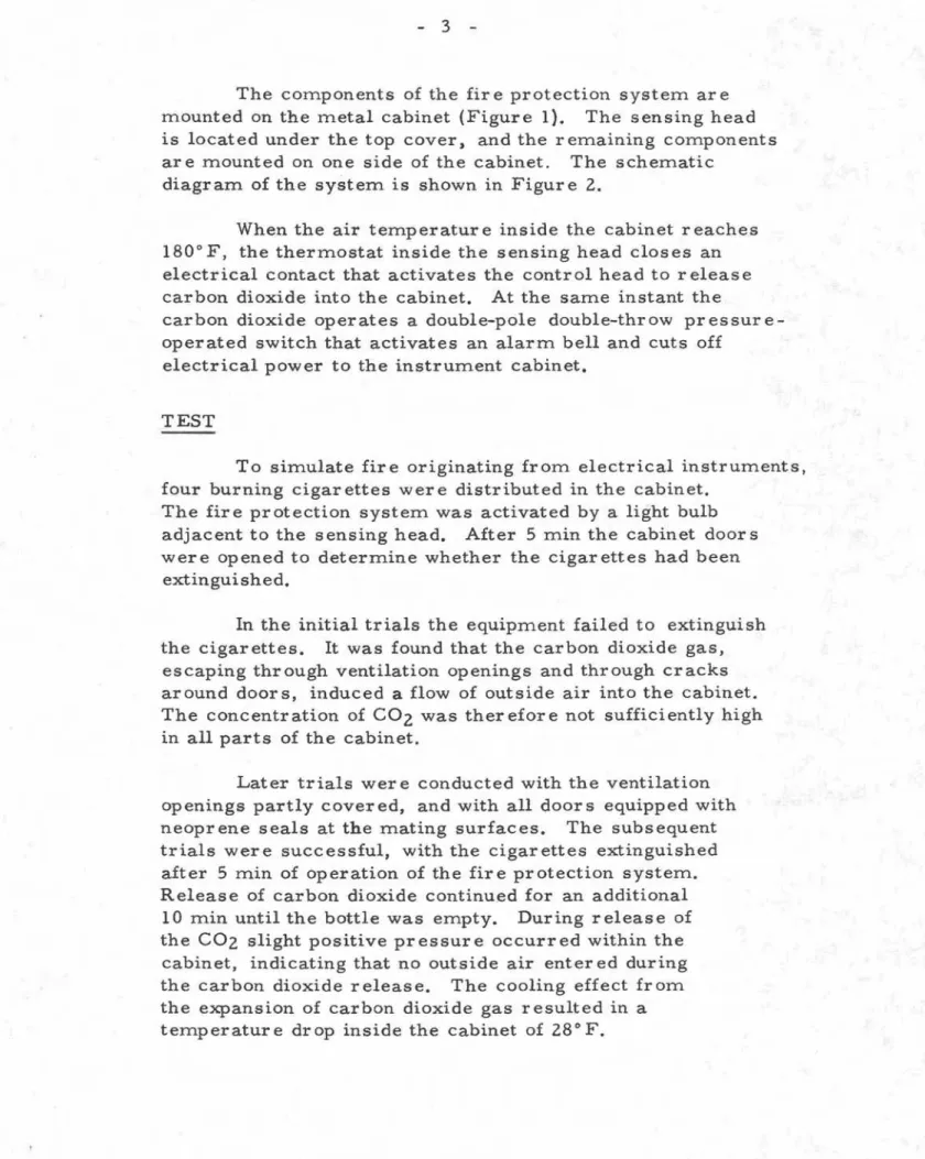
The components of the fir e protection system ar e mounted on the metal cabinet (Figure 1). The sensing head is located under the top cover) and the remaining components ar e mounted on one side of the cabinet. The schematic
diagram of the system is shown in Figure 2.
When the air temperatur e inside the cabinet reaches 1800
F, the thermostat inside the sensing head closes an electrical contact that activates the control head to release carbon dioxide into the cabinet. At the same instant the
carbon dioxide operates a double-pole double-throw pressure-operated switch that activates an alarm bell and cuts off
electrical power to the instrument cabinet.
TEST
To simulate fire originating from electrical instruments, four burning cigarettes were distributed in the cabinet.
The fire protection system was activated by a light bulb adjacent to the sensing head. After 5 min the cabinet doors were opened to determine whether the cigarettes had been extinguished.
In the initial trials the equipment failed to extinguish the cigarettes. It was found that the carbon dioxide gas,
escaping through ventilation openings and through cracks around doors, induced a flow of outside air into the cabinet. The concentration of C02 was therefore not sufficiently high in all parts of the cabinet.
Later trials wer e conducted with the ventilation op enings partly c over ed, and with all door s equipp ed with neoprene seals at the m.ating surfaces. The subsequent trials were successful, with the cigarettes extinguished after 5 m.in of operation of the fire protection system.. Release of carbon dioxide continued for an additional
10 min until the bottle was empty. During release of the C02 slight positive pressure occurred within the cabinet, indicating that no outside air enter ed during the carbon dioxide release. The cooling effect from. the expansion of carbon dioxide gas resulted in a tem.perature drop inside the cabinet of 280
_. 4
-Finally, with the electronic pressure-recording equipment installed and operating, the temperature rise inside the cabinet was 20° F - well under the upper operating temperatur e limit of the various instruments. With instruments having significantly high electrical power requirements it would be necessary to increase the amount of ventilation for normal operation. It would then be necessary to provide noncombustible cover s,
actuated by the fire protection system, to seal the openings in the event of fir e.
CONCLUSION
For the successful operation of a carbon dioxide extinguishing system, the instrument cabinet must be completely flooded with carbon dioxide to pr event outside air from entering the cabinet. It is necessary, therefore, to cover most ventilation openings and to provide seals to ensure tight -fitting door s. With these provisions the location of the spray nozzle inside the cabinet is unimportant. It should be noted that either adequate openings for ventilation or forced ventilation is required to pr event excessive temperatur e rise during normal operation.
Prior to installation of the instrument cabinet in a building, the fire protection system must be fully checked to locate any leaks in pipe fittings and to ensur e that the sealing of the cabinet is adequate. During long-term operation of the recording equipment, the carbon dioxide bottle must be weighed periodically to ensur e that the bottle contains the stated quantity of carbon dioxide.
The fir e protection system described in this Note is expected to reduce the potential risk of serious loss or damage from the spread of fire or smoke. The use of such a fire protection system, therefore, will improve the fire safety of automatic recording systems, particularly for unattended operation over long periods.