HAL Id: hal-00670193
https://hal.archives-ouvertes.fr/hal-00670193
Submitted on 14 Feb 2012
HAL is a multi-disciplinary open access
archive for the deposit and dissemination of
sci-entific research documents, whether they are
pub-lished or not. The documents may come from
teaching and research institutions in France or
abroad, or from public or private research centers.
L’archive ouverte pluridisciplinaire HAL, est
destinée au dépôt et à la diffusion de documents
scientifiques de niveau recherche, publiés ou non,
émanant des établissements d’enseignement et de
recherche français ou étrangers, des laboratoires
publics ou privés.
Laurent Rabbia, Vincent Perrut, Patrick Pons, Djemel Lellouchi
To cite this version:
Laurent Rabbia, Vincent Perrut, Patrick Pons, Djemel Lellouchi. Self-Assembled Monolayers
de-position in Supercritical Carbon Dioxide. MicroMechanics Europe Conference, Sep 2009, Toulouse,
France. 4 p. �hal-00670193�
--- ---
Self-Assembled Monolayers deposition
in Supercritical Carbon Dioxide
L. Rabbia
1, V. Perrut
1, P. Pons
2,3, D. Lellouchi
41
31 Degrees, 20 place Prax-Paris 82000 Montauban, France
2CNRS-LAAS ; 7 avenue du colonel Roche, F-31077 Toulouse, France
3Université de Toulouse ; UPS, INSA, INP, ISAE ; LAAS ; F-31077 Toulouse, France
4-NOVAMEMS,
10 av. de l'Europe 31520 Ramonville, France
---Abstract
Self-Assembled Monolayers of organic molecules have been successfully deposited onto wafer surface in supercritical carbon dioxide. Deposition method and apparatus are described. The layers are characterized by AFM and water droplet contact angle. Interest of this technique compared to liquid and vapor phase is discussed and studied for surface conversion from hydrophilic to hydrophobic for different materials.
Keywords : Self-Assembled Monolayers, grafting,
supercritical, carbon dioxide
I- Introduction
Among the processes being developed for MEMS and NEMS manufacturing, Self-Assembled Monolayers (SAM) deposition is becoming a critical step.
This process was originally developed in laboratories in liquid phase, in particular to modifiy silicon surface from hydrophilic to hydrophobic in a sustainable manner, in order to improve the reliability of the devices. Indeed, due to the high surface-to-volume ratio of the structures, strong adhesion forces can be developed depending on the surface energy of the materials [1]. Hydrophobic molecular layer coating with a negligible thickness reduces the surface energy and adhesion probability [2].
This method was extended to biology applications, to make surfaces biocompatible or for the realization of sensors (detection of amino acids, proteins, etc.). In this case, self-assembled functional molecules are laid on the surface, and selective markers are grafted onto them [3]. Other
applications for MEMS and semiconductor manufacturing have been also studied, like the formations of micropatterns [4] [5], gold coating [6], porous dielectric repair and sealing [7] and nanolithography [8].
Most of these processes were developed in solvent medium, as it does not require specific equipments. But the deposition process is very long because of the poor diffusivity and mobility of molecules in liquids. Moreover, this method gives very bad results in term of homogeneity on complex surface geometries or porous materials.
Vapor phase deposition of these SAM layers is also used [9]. This technique is claimed to have several advantages:
- Better coating uniformity for complex geometries thanks to a high diffusivity of molecules under vacuum;
- No solvent consumption;
- No drying after treatment. Integration of the process in a dry manufacturing line is facilitated (after dry etching for example);
- Process time greatly reduced: 30 minutes instead of several hours in liquid phase.
However, this technique is limited by the volatility of molecules to be grafted. Thus, solvent-based grafting remains the sole solution for many applications.
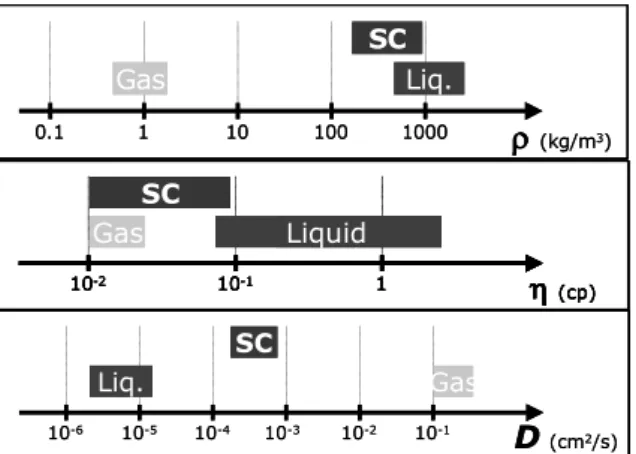
As alternative to these two methods, SAM grafting processes in supercritical CO2 is studied. Carbon dioxide in "supercritical" state has properties usually antagonistic particularly favourable for this application:
- Viscosity and diffusivity comparable to a gas; - Density close to a liquid. Moreover, CO2 acts as a non-polar solvent;
--- --- - Gas at ambient temperature and pressure: no
drying requested;
- Absence of phase transition between gas and supercritical: no risk of stiction during decompression;
- No drying issue (Dry-in / dry-out process). Physical properties of gas / liquids and supercritical fluids are compared on figure 1.
Moreover, this method is also environment-friendly, as very small amounts of precursor and solvent are required for the process.
Here are presented some properties of deposited films on various substrates and their resistance to temperature and aging.
II- Materials and method
Bare silicon and 500nm thermally-growth silicon oxide are studied. Prior to deposition process, silicon surface is cleaned by oxygen plasma followed by buffer HF. Silicon oxide is cleaned by
oxygen plasma.
Grafting process was performed on a R&D equipment built by SEPAREX in LAAS-CNRS cleanroom. Equipment operation is shown in Fig. 2. Two different processes can be used, either static or dynamic.
In dynamic process, the sample is placed is the chamber, then carbon dioxide (> 97 %) is pumped, pressurized up to 100 bar, and a constant flow is maintained through the chamber for 1 minute at 67 g.min-1. The temperature is adjusted between 40°C and 70°C. Then, a solution of precursor dissolved in a solvent, or pure precursor is injected in the carbon dioxide flow just before the chamber for 15 minutes. The sample is rinsed with pure SC CO2 during 5 minutes. Finally, the chamber is depressurized to atmosphere during 1 minute. In static process, sample and precursor are placed in the chamber, and carbon dioxide is pumped to a pressure of 100 bar, potentially including a co-solvent. Flow is stopped and the pressure is maintained in the chamber during 15 minutes. The sample is rinsed with pure SC CO2 during 5 minutes. Finally, the chamber is depressurized to atmosphere during 1 minute.
Precursors are asymmetrical molecules, with on reactive head able to create a covalent bond with the substrate and a functional tail, selected depending on desired surface properties. Reactive head is generally a silane group (chlorosilane, alkoxysilanes) as many substrates are silicon-based. But other reactive end-groups are also available. Here 3 molecules are deposited on the substrates: - A high performance lubricant. This molecule is
known to generate a 1 to 10 nm layer on
Fig. 2: Supercritical equipment schematics Fig. 1: Physical properties of gas, liquids an d
supercritical fluids D(cm2/s) 10-6 10-5 10-4 10-3 10-1 SC Liq. Gas 10-2 D (cm2/s) 10-6 10-5 10-4 10-3 10-1 SC Liq. Gas 10-2 D (cm2/s) 10-6 10-5 10-4 10-3 10-1 SC Liq. Gas 10-2
(kg/m3) 0.1 1 10 100 1000 SC Liq. Gas
(kg/m3) 0.1 1 10 100 1000 SC Liq. Gas
(kg/m3) 0.1 1 10 100 1000 SC Liq. Gas (cp) 10-2 10-1 1 SC Liquid Gas (cp) 10-2 10-1 1 SC Liquid Gas (cp) 10-2 10-1 1 SC Liquid Gas D(cm2/s) 10-6 10-5 10-4 10-3 10-1 SC Liq. Gas 10-2 D (cm2/s) 10-6 10-5 10-4 10-3 10-1 SC Liq. Gas 10-2 D (cm2/s) 10-6 10-5 10-4 10-3 10-1 SC Liq. Gas 10-2
(kg/m3) 0.1 1 10 100 1000 SC Liq. Gas
(kg/m3) 0.1 1 10 100 1000 SC Liq. Gas
(kg/m3) 0.1 1 10 100 1000 SC Liq. Gas D(cm2/s) 10-6 10-5 10-4 10-3 10-1 SC Liq. Gas 10-2 D (cm2/s) 10-6 10-5 10-4 10-3 10-1 SC Liq. Gas 10-2 D (cm2/s) 10-6 10-5 10-4 10-3 10-1 SC Liq. Gas 10-2
(kg/m3) 0.1 1 10 100 1000 SC Liq. Gas
(kg/m3) 0.1 1 10 100 1000 SC Liq. Gas
(kg/m3) 0.1 1 10 100 1000 SC Liq. Gas (cp) 10-2 10-1 1 SC Liquid Gas (cp) 10-2 10-1 1 SC Liquid Gas (cp) 10-2 10-1 1 SC Liquid Gas (cp) 10-2 10-1 1 SC Liquid Gas (cp) 10-2 10-1 1 SC Liquid Gas (cp) 10-2 10-1 1 SC Liquid Gas (cp) 10-2 10-1 1 SC Liquid Gas (cp) 10-2 10-1 1 SC Liquid Gas (cp) 10-2 10-1 1 SC Liquid Gas--- --- materials and is selected here as reference ;
- A fluorinated molecule with monofunctional end-group - called SAM1 ;
- A trifunctional alkoxysilane hydrocarbon called SAM2.
The lubricant is deposited in static mode, and will only get adsorbed on the substrate surface. The 2 other molecules are deposited in dynamic mode and are selected to react with the substrate surface to create covalent bonds.
III- Characterization
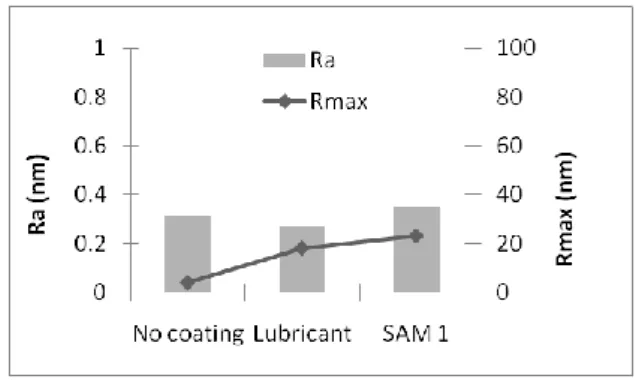
Roughness measurements by AFM give complementary information for unperfected deposition processes leading to polymerization of precursors and formation of rough and thicker films (tapping/phase mode). Values Ra (mean height difference) and Rmax (max height difference) are measured on 10µm x10µm scans.
Water droplet contact angle measurements are performed on a Digidrop equipment from GBX, in order to evaluate hydrophilic or hydrophobic character of the modified surfaces. Surfaces with an angle lower than 90° are hydrophilic and those with an angle larger than 90° are hydrophobic.
IV- Results
Surface properties
Figure 3 summarizes water droplet contact angle variation with SAM deposition. Prior to SAM grafting, Silicon oxide is highly hydrophilic (contact angle 7°) and Si hydrophobic (contact angle 80°) due to HF treatment. But Si-surface is not stable and in a few hours, contact angle decreases to 30-40° as the surface oxidizes.
Lubricant and SAM2 show a good efficiency for both substrates, with angle values between 97 and 102°. In the contrary, SAM1 is strongly selective as it does not modify SiO2 surface and shows a good efficiency with bare silicon.
As illustrated by figures 4 and 5, roughness modification is not significant, except for SAM2 layer on SiO2, with a strong increase of Rmax. AFM scan confirms on figure 6 the surface modification by the formation of aggregates, with height up to 100 nm. SAM2 is a multifunctional molecule and it s assumed that it formed polycondensed layers on substrate surface.
Fig. 3: Water droplet contact angle measurement pre and post coating process
Fig. 4: Roughness measurement on silicon
Fig. 5: Roughness measurement on silicon oxide
Resistance to thermal treatment
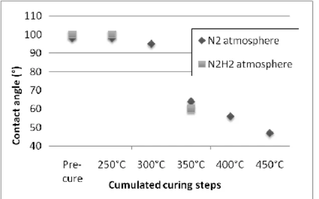
Substrates coated with SAM1 and SAM2 are subjected to thermal curing in order to evaluate their resistance to temperature. Lubricant coating was not evaluated, as its thermal resistance is already known to be 250°C. The samples are cured in a furnace at atmospheric pressure, with a flow of
Fig. 6 : AFM 3D topography for SiO2 surface
--- --- nitrogen or N2H2. Nitrogen flow does no totally
eliminate oxygen, so oxidation should be observed. On the contrary N2H2 is a slightly reductive atmosphere. Thermal treatments of one hour are consecutively done on the same samples with temperature increase at each time and contact angle measurement in between. Results are presented on figures 7 and 8. It appears that no significant change is observed up to 300°C and even 350°C for SAM2 under N2 atmosphere.
Fig. 7: Thermal resistance of SAM1 layer on silicon
Fig. 8: Thermal resistance of SAM2 layer on silicon oxide
Resistance to accelerated aging
Accelerated aging was performed on samples: 600 hours in a climatic chamber at 80°C and 85% humidity and 600 hours in dry air at 125°C. Contact angle variations are presented on figures 9 and 10 and demonstrate that the lubricant is slightly sensitive to moisture and SAM layers have a lower resistance at 125°C.
V- Conclusion
This study demonstrates the feasibility to graft SAM layers in supercritical carbon dioxide. Deposition selectivity towards materials and process integration for standard MEMS components will be further studied to avoid potential bonding failures or electrical contact
defectivity wich may occur.
Fig. 9: Aging resistance of SAM1 layer on silicon
Fig. 10: Aging resistance of SAM2 layer on silicon oxide
VI- References
[1] N. S. Tambe, B. Bhushan, Nanotechnology, 15, 2004, pp1561-1570
[2] U. Srinivasan, M. R. Houston, J. of Microelectromechanical Systems, 7 (2), 1998 [3] H.C.W. Hays & al., Sensors and Actuators B,
114, 2006, pp1064–1070
[4] N. Saito, H. Haneda & Al., Adv. Mater., 14 (6), 2002
[5] X. Chen, L. M. Tolbert & Al., J. Vac. Sci. Technol. B, 19 (6), 2001
[6] C. D. Bain, E.B. Troughton & Al., J. Am. Soc.,
111, 1989, pp321-335
[7] Y. S. Mor, T. C. Chang & Al., J. Vac. Sci. Technol. B, 20 (4), 2002
[8] M. J. Lercel, H.G. Craighead & Al., Appl. Phys. Lett, 68 (11), 1996
[9] P. W. Hoffmann, M. Stelzle, J. F. Rabolt, Langmuir, 13, 1997, pp1877-1880