HAL Id: hal-03023677
https://hal.archives-ouvertes.fr/hal-03023677
Submitted on 25 Nov 2020HAL is a multi-disciplinary open access archive for the deposit and dissemination of sci-entific research documents, whether they are pub-lished or not. The documents may come from teaching and research institutions in France or abroad, or from public or private research centers.
L’archive ouverte pluridisciplinaire HAL, est destinée au dépôt et à la diffusion de documents scientifiques de niveau recherche, publiés ou non, émanant des établissements d’enseignement et de recherche français ou étrangers, des laboratoires publics ou privés.
Modelling active dipolar media in photonics and
optoelectronics with the finite element method
Faten Ben Chaabane, Thomas Lopez, Laetitia Pradere, Béatrice Dagens,
Aloyse Degiron
To cite this version:
Faten Ben Chaabane, Thomas Lopez, Laetitia Pradere, Béatrice Dagens, Aloyse Degiron. Modelling active dipolar media in photonics and optoelectronics with the finite element method. Journal of Physical Chemistry C, American Chemical Society, 2020, �10.1021/acs.jpcc.0c07069�. �hal-03023677�
Modelling active dipolar media in photonics and
optoelectronics with the finite element method
Faten Ben Chaabane1,2, Thomas Lopez2, Laetitia Pradere2, Béatrice Dagens1, Aloyse Degiron3,*
1Université Paris Saclay, CNRS, Centre de Nanosciences et de Nanotechnologies, Palaiseau,
France
2Groupe PSA, Centre Technique de Vélizy, Vélizy-Villacoublay, France
3Université de Paris, CNRS, Laboratoire Matériaux et Phénomènes Quantiques, Paris, France
KEYWORDS: finite element method, nonlinear active media, nonlinear nanophotonics, strong coupling, collective states
ABSTRACT: We introduce a simple and efficient numerical method to model the nonlinear response of active dipolar media in arbitrary photonic environments in the harmonic regime. At variance with existing approaches that require a deep knowledge of time-domain resolution techniques, our model is based on a reformulation in the frequency domain of the rate equations that govern the behavior of active dipolar media. The resulting equations can then be readily solved with popular solvers based on the finite element method. We discuss the validity of the method for a single layer of organic molecules and then illustrate its potential by studying the strong coupling between the molecules and an array of plasmonic nanoparticles. The model correctly predicts the formation of strongly coupled states and also captures more subtle features linked to dipole-dipole interactions.
1. Introduction
Many research topics in photonics and optoelectronics involve interactions between optical nanostructures and dipolar media (e.g. layers of organic molecules, semiconducting nanocrystals, quantum wells…). This is of course the case for lasers, with current developments focused on topologically protected cavities [1] and parity-time symmetry for enhanced modal purity [2]. One can also cite the staggering breakthroughs accomplished with optical cavities in the strong coupling regime, such as the possibility of using hybrid light-matter states to enhance the optoelectronic properties of the dipolar medium [3] or to engineer the kinetics of chemical reactions in radically new ways [4]. Also worth mentioning are novel avenues for second harmonic generation in nanoscale systems [5,6] and the emerging potential of collective superradiant states for infrared optoelectronic devices [7].
To model the interactions of a dipolar medium and its surrounding photonic environment, a semi-classical treatment based on the matrix density formalism can be applied in many cases of interest [8]. This general framework makes it possible to evaluate how the different energy levels of the system are populated and, in turn, how these populated states influence the optical properties of the structure under investigation. In mathematical terms, the problem can be formulated as a system of rate equations coupled to Maxwell’s equations that must be solved in a self-consistent way. For nanostructures, it is generally not possible to solve these equations analytically due to the complexity of the electromagnetic fields associated with subwavelength features. It is therefore necessary to rely on numerical simulations. Because the rate equations are time-dependent, they are usually solved in the time domain, typically using the Finite-Difference Time-Domain (FDTD) method [8].
Although FDTD has proven highly successful, its implementation is everything but straightforward for the class of problems involving active dipolar media. In fact, there are many pitfalls and subtleties that are not handled by commercial FDTD software and therefore advanced skills are necessary to develop home-built codes [8]. Furthermore, for all the cases that do not deal with transient processes, the photonics community tends to favor another numerical approach— the finite element method (FEM). Contrarily to FDTD, the FEM is usually formulated in the frequency domain. It is used by many groups in the world to solve a large variety of electromagnetic problems such as the scattering of subwavelength nanoparticles [9], the mode propagation in optical and plasmonic waveguides [10] or the design of topological metamaterials [11]. Although most of the FEM models built by the community deal with passive linear problems, the method has been successfully adapted to active, nonreciprocal and nonlinear systems such as Parity Time symmetric structures [12], nonreciprocal metamaterials [13], nonlinear plasmonic waveguides [14] and nonlinear metasurfaces [6]. However, none of these developments tackles the important class of problems involving interactions between electromagnetic fields and dipolar media described by rate (or population) equations.
In this article, we address this problem by rewriting the population equations of a dipolar medium in the frequency domain. The expressions are then included in a self-consistent electromagnetic model solved with a commercial finite element solver (Comsol Multiphysics). We first discuss the accuracy and limitations of the model for a simple organic layer surrounded by air. We then illustrate the potential of our approach by examining the strong coupling between this organic layer and an array of plasmonic nanoparticles.
2. Methods
We consider the case of a two-level dipolar medium and write n1 and n2 the populations in the
ground and excited states, respectively. Furthermore, we assume an isotropic distribution of the transition dipole moments and write their norm as µ12. Under these assumptions, the response of
the material to a local electric field E⃗⃗ can be expressed using the density matrix method as [8]: dn1 dt − γ21n2 = − 1 ℏΩ0E⃗⃗ . ∂P⃗⃗ ∂t (1.a) dn2 dt = − dn1 dt (1.b) ∂2P⃗⃗ ∂t2+( γ21+ 2γd) ∂P⃗⃗ ∂t+ Ω0 2P⃗⃗ = − κ(n 2− n1)E⃗⃗ , (1.c)
where γ21 is the spontaneous decay rate of the excited state, γd is the pure dephasing rate, ħΩ0 is
the transition energy, P⃗⃗ is the macroscopic polarization and κ= 2Ω0µ122/3ħ is a coupling constant.
Note that these expressions take into account the dipole-dipole interactions between individual molecules—a point that will be critical later on.
We look for an equivalent formulation of these equations in the harmonic regime. To this end, we formally express the x, y and z components of the polarization and the electric field as:
pi =1 2[|Pi| e j[arg(Pi)+ωt] + c. c. ] (2.a) ei = 1 2[|Ei| e j[arg(Ei)+ωt] + c. c. ] (2.b)
where Pi and Ei are the ith components of the complex polarization and electric field phasors and
i= x, y, z. After some algebraic manipulations, and by noting that in the harmonic regime, the n1
and n2 populations are time-independent on average, we can recast the original system of equations
〈n2〉 = 1 ℏ Ω0 γ21〈E⃗⃗ . ∂P⃗⃗ ∂t〉 = −ω
2ℏ Ω0 γ21 ∑ |Pi i| |Ei| sin[arg(Pi) − arg(Ei)] (3.a)
〈n1〉 = n0− 〈n2〉 (3.b)
[Ω02− ω2+ jω(γ21+ 2γd)]Pi = − κ(2〈n2〉 − n0)Ei (3.c)
where < . > denotes time-averaged quantities, i = x, y, z and n0 is the total molecular, atomic or
electronic density.
The last step to include equations (3.a)-(3c) in a finite element model in the frequency domain is to express the relative complex permittivity εr of the dipolar medium as a diagonal tensor:
εr,ii = 1 + Pi/ ε0Ei , i=x, y, z (4)
3. Results and Discussion
3.1 Validation of the model
We test the validity of our approach by examining the properties of a molecular layer illuminated by a plane wave under normal incidence. The layer has a thickness t=15 nm and is surrounded by air on both sides. In this example, we consider molecular parameters already considered in the literature [15], namely, a transition energy ħΩ0 = 2.94 eV, a spontaneous decay rate γ21 = 1 ps-1, a
pure dephasing rate γd = 730 fs-1 and a transition dipole moment µ12=10 D.
We build our model in the commercial software Comsol Multiphysics. We use the predefined environment offered by the RF module to set the electromagnetic part of the problem based on Maxwell’s equations. To include the molecular response, we enter eqs 3a-3c manually by creating an additional “Domain ODEs and DAEs” node within the model. The two sets of equations are coupled by ascribing the complex permittivity given by eq 4 to the molecular layer. Because the
problem is intrinsically nonlinear, we compute the solution iteratively, using a multifrontal massively parallel sparse direct solver at each step and converging toward the solution with the Newton’s method (this is the strategy implemented by default in Comsol).
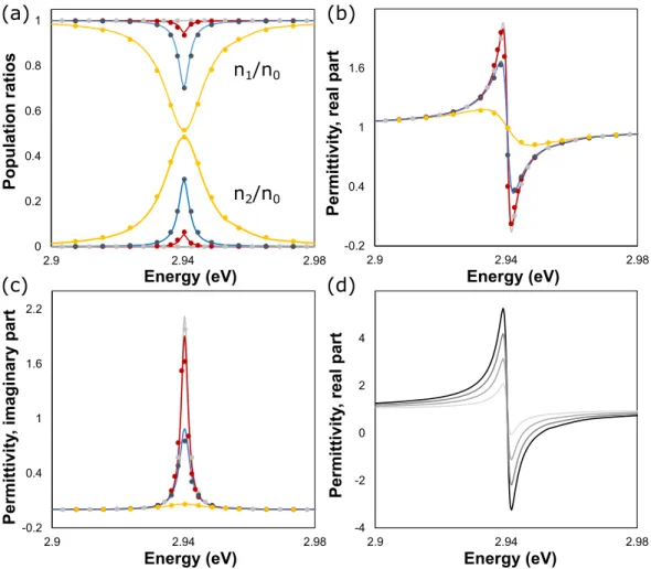
Figure 1a shows the evolution of the populations <n1> and <n2> as a function of the incident power.
The total molecular density chosen in this first example is n0=1025 m-3. In all cases, the molecules
are resonantly pumped around the frequency Ω0 of the molecular transition, which is the expected
behavior. As the incident power increases, the fundamental level is gradually depleted and it is possible to reach a point where approximately half of the population is in the excited state. Importantly, our model does not converge for incident powers that exceed this threshold because no population inversion can be observed with a two-level system in the steady state. The reason why the model does not find solutions for <n2> larger than <n1> is encoded in eq 3c. The term
2<n2>-n0 = <n2>-<n1> on the right side of this equation must always be negative, otherwise the
molecular susceptibility and permittivity εr are not self-consistent (i.e. the susceptibility and
permittivity would exhibit an anomalous dispersion outside the resonance, as can be seen by noting that eq 3c can be recast as the ith component of the electric susceptibility P
i/ε0Ei).
Figures 1b-1c show that the real and imaginary parts of εr have a resonant shape, as expected for
a material with resonant transitions around Ω0. Furthermore, the strength of the resonance weakens
as the power increases, which is also consistent with the fact that the interactions with the incident field decrease as more and more molecules leave the ground state.
The molecular film considered in this first example is sufficiently thin that all the solved quantities are almost invariant along the propagation direction. Thus, the same problem can also be directly solved in the time domain with eqs 1a-1c because the latter admit tractable solutions (i.e. without
using brute-force FDTD) in the limit of vanishingly thin films. The results of the time-domain calculations, performed with the help of a small code written in Octave, are shown as filled symbols on Figures 1a-1c. They are in excellent agreement with the Comsol simulations, validating our FEM model.
We close this section by noting that the other key parameter that influences the response of the molecular layer is the total molecular density n0. This point is illustrated on Figure 1d where the
real part of the permittivity is plotted for a fixed incident power P=12.5 MW/m and increasing values of n0. One can see that the Lorentzian-like features sharpen as n0 increases, which is not
surprising given that more molecules are involved in the interactions. Interestingly, εr can even
reach negative values for the highest molecular concentrations, which is indicative of a metallic behavior. Note that in this case also, the model only finds solutions characterized by <n1> > <n2>.
We remind the reader that this is not an intrinsic limitation of our approach but a consequence of the fact that we consider a two-level system in the steady state. Had we considered a medium with three levels or more, population inversion would have been possible.
3.2 Application to Strong Coupling
We now illustrate the potential of our approach by examining the strong coupling between the generic two-level molecular emitters investigated above and an array of resonant plasmonic nanoparticles. We have chosen this example because it has a rich physics that has already been well studied with FDTD simulations [15,16]. In other words, we can use this system to verify that our FEM model captures all the features predicted with simulations performed in the time domain—and also provide additional quantitative insight on this system.
The structure under investigation, shown in Figure 2, differs from the existing literature on two points. First, the plasmonic array has not the same geometry. Second, the coupled organic/plasmonic system is embedded within an inverted organic LED architecture, so that the results presented below may be used to develop electroluminescent devices in the future. The full stack consists of an Al cathode, a TiO2 film to inject the electrons, the plasmonic array, the generic
two-level dipolar medium and a transparent cover with a refractive index close to that of ITO. It may be argued that this stack lacks of hole injection layer (HIL) and transport hole layer (HTL), but studies on quantum dot LEDs have shown that these layers and the transparent ITO anode can be optically modeled as a single material [17].
Here, we will solely focus on the passive optical properties of the device. Specifically, we model the system following the guidelines exposed previously and examine the reflection properties of the device when the latter is illuminated by an incoming plane wave under normal incidence. Rather than simulating the full structure, we model a single unit cell and apply periodic boundary conditions on the lateral sides of the computational domain. The periods that will be considered below are always smaller than the wavelength so that no diffraction effect modulates the optical response of the system.
Figure 3a shows the result of the simulations for four molecular densities n0 ranging from 1023 m -3 to 5×10²³ m-3. The reflection spectra exhibit two dips on each side of the molecular transition
frequency. Furthermore, the separation between these two minima increases with n0, suggesting
that they are the signature of the strong coupling between the molecular system and the plasmonic resonances of the Al nanoparticules. This interpretation is confirmed with the calculations of Figure 3b which shows, for the molecular density n0 = 5×10²³ m-3, the position of the two minima
and the dispersion of the plasmonic resonance Epl(P) without the organic layer. A clear anticrossing
with a Rabi splitting of 20 meV is observed. Furthermore, the branches have the expected polaritonic behavior, as they can be fitted by the analytical eigenmodes resulting from the hybridization of ħΩ0 and Epl(P) via a coupling term being half of the Rabi splitting [18] (continuous
lines on Figure 3b).
We have then repeated the simulations for molecular concentrations ranging from 1024 m-3 to
4×1024 m-3. As shown on Figure 3c and Figure 3d, the splitting between the two polaritonic
branches further increases and a new minimum emerges near the transition energy of the molecules (2.94 eV). This nearly dispersionless feature has been noted by other authors who studied similar structures in the past [15,20,21]. They argued that it corresponds to the emergence of a new collective mode at high molecular concentrations n0. This assertion was supported by a qualitative
analytical model and by the fact that the mode emerges when the permittivity of the molecular layer becomes negative. In our case also, we have verified that this mode appears when the real part of εr reaches negative values near the resonance frequency (Figure 1d). As discussed in the
previous section, a negative permittivity implies that the medium acts as a metal at optical frequencies, which, by definition, implies a screening of the incoming field—and therefore constructive interferences resulting from the cooperation of all the dipoles of the medium. As a corollary, the results of Figures 3c-3d suggest that dipole-dipole interactions are correctly taken into account by our model—without them, the cooperative behavior between the molecules would not be captured and the third mode would not occur [22].
The third mode should not be confused with the signature of the dipoles that remain uncoupled in real experiments [23] or with the collective subradiant modes resulting from inhomogeneous broadening [24]. To support this claim, we have repeated the calculations after setting the emitter’s
dephasing time to zero and reducing their decay rate by an order of magnitude, so as to emulate a dipolar medium with vanishing spectral broadening and almost no losses. The results, plotted in the inset of Figure 3d, prove that the third mode still exists in this case—a point that has never been verified to our knowledge.
4. Conclusion
In conclusion, we have presented a numerical method to include the response of a two-level dipolar medium in electromagnetic finite element simulations in the frequency domain. Our approach has a general validity and can be adapted to other nonlinear problems involving media described by rate/population equations, including those with more than two energy levels. In this regard, it may be of interest for anyone using the finite element method as their primary design tool in photonics, optoelectronics and material sciences.
AUTHOR INFORMATION
Corresponding Author
*E-mail: (A.D.) [email protected] ACKNOWLEDGMENT
This work was supported by Groupe PSA through Contract CIFRE No 2017/0535 as part of the projects of the OpenLab PhOVeA.
REFERENCES
[1] Bandres, M. A.; Wittek, S.; Harari, G.; Parto, M.; Ren, J.; Segev, M.; Christodoulides, D. N.; Khajavikhan, M. Topological Insulator Laser: Experiments. Science 2018, 359, eaar4005.
[2] Feng, L. Wong, Z. J.; Ma, R.-M. Wang, Y.; Zhang, X. Single-Mode Laser by Parity-Time Symmetry Breaking. Science 2014, 346, 972–975.
[3] Orgiu, E.; George, J.; Hutchison, J. A.; Devaux, E.; Dayen, J.-F.; Doudin, B.; Stellacci, F.; Genet, C.; Schachenmayer, J.; Genes, C.; Pupillo, G.; Samorì P.; Ebbesen, T. W. Conductivity in Organic Semiconductors Hybridized with the Vacuum Field. Nat. Mater. 2015, 14, 1123–1129. [4] Hutchison, J. A.; Schwartz, T.; Genet, C.; Devaux, E.; Ebbesen, T. W. Modifying Chemical Landscapes by Coupling to Vacuum Fields. Angew. Chem. Int. Ed. 2012, 51, 1592 –1596.
[5] Cox, J. D.; Singh, M. R.; von Bilderling, C.; Bragas, A. V. A Nonlinear Switching Mechanism in Quantum Dot and Metallic Nanoparticle Hybrid Systems. Adv. Opt. Mater. 2013, 1, 460 – 467. [6] Gigli. C; Wu T.; Marino G. ; Borne A. ; Leo G. ; and Lalanne P. Quasinormal-Mode Non-Hermitian Modeling and Design in Nonlinear Nano-Optics.ACS Photon. 2020, 7, 1197–1205.
[7] Vasanelli, A.; Todorov, Y.; Sirtori, C. Ultra-Strong Light–Matter Coupling and Superradiance Using Dense Electron Gases. C. R. Phys. 2016, 17, 861–873.
[8] Sukharev, M.; Nitzan, A. Optics of Exciton-Plasmon Nanomaterials. J. Phys.: Condens.
Matter. 2017, 29, 443003.
[9] Knight, M. W.; Halas, N. J. Nanoshells to Nanoeggs to Nanocups: Optical Properties of Reduced Symmetry Core–Shell Nanoparticles Beyond the Quasistatic Limit. New J. Phys. 2008, 10 105006.
[10] Zenin, V. A.; Volkov, V. S.; Han, Z.; Bozhevolnyi, S. I.; Devaux, E.; Ebbesen, T. W. Directional Coupling in Channel Plasmon Polariton Waveguides. Opt. Express 2012, 20, 6124– 6134.
[11] Yves, S.; Fleury, R.; Berthelot, T.; Fink, M.; Lemoult, F.; Lerosey G. Crystalline Metamaterials for Topological Properties at Subwavelength Scales. Nat. Commun. 2017, 8, 16023. [12] Benisty, H.; Degiron, A.; Lupu, A. ; De Lustrac, A. ; Chénais, S. ; Forget, S. ; Besbes, M.; Barbillon, G.; Bruyant, A.; Blaize, S.; Lérondel, G. Implementation of PT Symmetric Devices Using Plasmonics: Principle and Applications. Opt. Express 2011, 19, 18004-18019.
[13] Degiron. A.; Vanwolleghem. M.; Smith, D.R. Efficient Finite Element Resolution of Gyromagnetic and Gyroelectric Nonreciprocal Electromagnetic Problems. Opt. Express 2017, 25, 11088–11102.
[14] Degiron. A.; Smith D.R. Nonlinear Long-Range Plasmonic Waveguides. Phys. Rev. A 2010, 82, 033812.
[15] Fauché. P.; Gebhardt. C.; Sukharev. M.; Vallée, R.A.L.; Plasmonic Opals: Observation of a Collective Molecular Exciton Mode Beyond the Strong Coupling. Sci. Rep. 2017, 7, 4107.
[16] Sukharev. M.; Nitzan. A. Plasmon Transmission Through Excitonic Subwavelength Gaps. J.
Chem. Phys. 2016, 144, 144703.
[17] Wang, H.; Le-Van, Q.; Aassime, A.; Le Roux, X.; Charra, F.; Chauvin, N.; Degiron, A. Electroluminescence of Colloidal Quantum Dots in Electrical Contact with Metallic Nanoparticles. Adv. Optical Mater. 2018, 6, 1700658.
[18] Bellessa, J.; Bonnand, C.; Plenet, J. C.; Mugnier, J. Strong Coupling between Surface Plasmons and Excitons in an Organic Semiconductor. Phys. Rev. Lett. 2004, 93, 036404.
[19] Rakić, A.; Djurišić, A. B.; Elazar, J. M.; Majewski, M. L. Optical properties of metallic films for vertical-cavity optoelectronic devices. Appl. Opt. 37, 5271–5283(1998).
[20] Salomon, A.; Wang, S.; Hutchison, J. A.; Genet, C.; Ebbesen, T. W. Strong Light-Molecule Coupling on Plasmonic Arrays of Different Symmetry. ChemPhysChem 2013, 14, 1882–1886. [21] Antosiewicz, T. J.; Apell, S. P.; Shegai, T. Plasmon−Exciton Interactions in a Core−Shell Geometry: From Enhanced Absorption to Strong Coupling. ACS Photon. 2014, 1, 454–463. [22] Salomon, A.; Gordon, R. J.; Prior, Y.; Seideman, T.; Sukharev, M. Strong Coupling between Molecular Excited States and Surface Plasmon Modes of a Slit Array in a Thin Metal Film. Phys.
Rev. Lett. 2012, 109, 073002.
[23] Aberra Guebrou, S.; Symonds, C.; Homeyer, E.; Plenet, J. C.; Gartstein, Yu. N.; Agranovich, V. M.; Bellessa, J. Coherent Emission from a Disordered Organic Semiconductor Induced by Strong Coupling with Surface Plasmons. Phys. Rev. Lett. 2012, 108, 066401.
[24] Houdré, R.; Stanley, R. P.; Ilegems, M. Vacuum-Field Rabi Splitting in the Presence of Inhomogeneous Broadening: Resolution of a Homogeneous Linewidth in an Inhomogeneously Broadened System. Phys. Rev. A 1996, 53, 2711–2715.
FIGURES
Figure 1. Optical properties of a layer of two-level emitters surrounded by air on both sides. (a)
Population ratios computed at the molecular density n0 = 1025 m-3 for different input powers
(respectively 12.5 MW/m, 1.25 GW/m, 125 GW/m and 2500GW/m for the grey, red, blue and yellow curves). (b) and (c) Real and imaginary parts of the layer permittivity for the same cases. The continuous curves of these three plots are the output of the finite element model while the filled symbols are the results obtained by directly solving eqs 1a-1c. (d) Real part of the permittivity for an input power of 12.5 MW/m and different molecular concentrations (respectively 1025 m-3, 2×1025 m-3, 3×1025 m-3 and 4×1025 m-3 for the curves with increasingly darker shades of
Figure 2. Schematic of one unit cell of the periodic structure examined for strong coupling. The Al
nanoparticles have a length L = 75 nm and a thickness t = 25 nm. The period is treated as a parameter that will be subsequently varied between 290 nm and 340 nm. The refractive indices of Al and TiO2 are taken
from two references of the literature [17, 19] while the top layers on top of the molecular film are modeled as a single material with the refractive index of ITO multiplied by 1.25 for the real part [17]. Note that we model the Al nanoparticles with a bulk refractive index, but since we deal with nanorods that are separated by hundreds of nanometers, deviations from the bulk (such as nonlocal effects) are weak.
Figure 3. (a) Reflection spectra for a structure with a period P = 320 nm. The molecular
concentrations n0 are 1023 m−3 for the light blue curve, 2×10²³ m−3 for the blue curve, 3×10²³ m−3
for the red curve and 5×10²³ m−3 for the gray curve. The vertical dashed line indicates the molecular
transition energy ħΩ0 and the black spectrum reveals the uncoupled plasmonic resonance Epl when
the simulations are performed without the organic layer. (b) Dispersion relation for n0 = 5×10²³
m−3. The filled symbols are the output of the FEM simulations for different periods P while the
continuous curves result from the diagonalization of the 2×2 Hamiltonian hybridizing ħΩ0 and
Epl(P). The uncoupled parameters ħΩ0 and Epl(P) are visualized as gray and black dashed lines,
respectfully. (c) Reflection spectra for molecular concentrations n0 = 1024 m−3, 2×1024 m−3, 3×1024
m−3 and 4×1024 m−3. (d) Dispersion relation for n
0 = 4×1024 m−3. The new collective mode that
appears close to the molecular transition is seen as yellow symbols. Inset: result of the simulations when the dephasing rate of the emitters is set to zero and their decay rate reduced by one order of magnitude.