Images in cardio-thoracic surgery
Slicing the LionHeart for assessment of pump shortening
fraction after 1 year of follow-up
1
S. Qanadli
a, P. Tozzi
b, P. Schnyder
a, L.K. von Segesser
b,*
a
Department of Radiology, Centre Hospitalier Universitaire Vaudois, CHUV, CH-1011, Lausanne, Switzerland
bDepartment of Cardio-vascular Surgery, Centre Hospitalier Universitaire Vaudois, CHUV, CH-1011, Lausanne, Switzerland
Received 15 June 2003; received in revised form 20 July 2003; accepted 22 July 2003
Keywords: Left ventricular assist device; Destination therapy; Transcutaneous energy transfer; Totally implanted pump; Terminal heart failure; Multi-slice CT-scan
A 75-years-old outpatient who had received a permanent,
fully implanted left ventricular assist system (LVAS:
LionHeart, Arrow International, Reading, PA, USA) for
destination therapy of his end stage (class IV) congestive
heart failure, underwent planned control examinations at 12
months of follow-up including a multi-slice CT-scan.
Fig. 1
shows the positions of the implanted LVAS with its
subsystems. The LVAS slices shown in
Fig. 2
allow for
measurement of the pump shortening fraction (. 80%). The
device output (approx. 4.7 l/min) can be estimated by taking
in account the pump stroke rate (approx. 90), which is
derived from the uncompressed video 1
1. Multi-slice CT
examination allows for in vivo assessment of totally
implanted ventricular assist systems and their function or
malfunction (e.g. thrombus detection, etc.).
European Journal of Cardio-thoracic Surgery 24 (2003) 642–643
www.elsevier.com/locate/ejcts
1010-7940/$ - see front matter q 2003 Published by Elsevier B.V. doi:10.1016/S1010-7940(03)00473-1
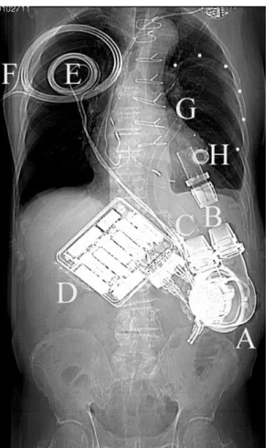
Fig. 1. Subsystems of the fully implanted LVAS including the blood pump (A) connected to the apex of the left ventricle (B) and the ascending aorta (C), the motor controller with the batteries (D) allowing the patient to be completely unthethered for about 20 min, the internal (E) and external (F) coils for transcutaneous energy transmission, the connecting line (G) between the blood pump housing and the compliance chamber (dots), and the access port (H) for volume adjustment of the latter.
* Corresponding author. Tel.: 80; fax: þ41-21-314-22-78.
E-mail address: [email protected] (L.K. von Segesser).
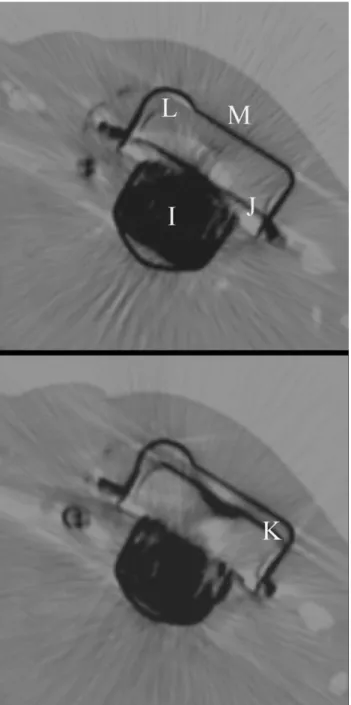
Fig. 2. LVAS blood pump slices are depicted with the motor (I), pusher plate in diastolic (J), and systolic position (K). Pump blood sac (L) compression can be derived from the pusher plate displacement, which provides a shortening fraction {[diastolic minus systolic distance between housing (M) and pusher plate] divided by [diastolic distance between housing and pusher plate]} of 0.83 or an ejection fraction equivalent of more than 80% (multi-slice CT).