Dislocations Accelerate Oxygen Ion Diffusion in La[subscript
0.8]Sr[subscript 0.2]MnO[subscript 3] Epitaxial Thin Films
The MIT Faculty has made this article openly available.
Please share
how this access benefits you. Your story matters.
Citation
Navickas, Edvinas et al. “Dislocations Accelerate Oxygen Ion
Diffusion in La[subscript 0.8]Sr[subscript 0.2]MnO[subscript 3]
Epitaxial Thin Films.” ACS Nano 11, 11 (October 2017): 11475–11487
© 2017 American Chemical Society
As Published
http://dx.doi.org/10.1021/ACSNANO.7B06228
Publisher
American Chemical Society (ACS)
Version
Final published version
Citable link
http://hdl.handle.net/1721.1/117130
Terms of Use
Article is made available in accordance with the publisher's
policy and may be subject to US copyright law. Please refer to the
publisher's site for terms of use.
Johannes Bernardi,
Michael Sto
̈ger-Pollach,
Gernot Friedbacher,
Herbert Hutter,
Bilge Yildiz,
*
and Ju
̈rgen Fleig
*
,††Institute of Chemical Technologies and Analytics, Vienna University of Technology, Getreidemarkt 9, Vienna A-1060, Austria ‡Department of Nuclear Science and Engineering and§Department of Materials Science and Engineering, Massachusetts Institute of
Technology, 77 Massachusetts Avenue, 24-107, Cambridge, Massachusetts 02139, United States
∥University Service Centre for Transmission Electron Microscopy, Vienna University of Technology, Wiedner Hauptstr. 8-10, Vienna
A-1040, Austria
⊥Next-Generation Fuel Cell Research Center (NEXT-FC) and #International Institute for Carbon-Neutral Energy Research
(WPI-I2CNER), Kyushu University, 744 Motooka, Nishi-ku, Fukuoka 819-0395, Japan
*
S Supporting InformationABSTRACT: Revealing whether dislocations accelerate oxygen ion transport is important for providing abilities in tuning the ionic conductivity of ceramic materials. In this study, we report how dislocations affect oxygen ion diffusion in Sr-doped LaMnO3(LSM), a model perovskite
oxide that serves in energy conversion technologies. LSM epitaxial thinfilms with thicknesses ranging from 10 nm to more than 100 nm were prepared by pulsed laser deposition on single-crystal LaAlO3and SrTiO3substrates. The lattice
mismatch between the film and substrates induces compressive or tensile in-plane strain in the LSM layers. This lattice strain is partially reduced by dislocations,
especially in the LSMfilms on LaAlO3. Oxygen isotope exchange measured by secondary ion mass spectrometry revealed
the existence of at least two very different diffusion coefficients in the LSM films on LaAlO3. The diffusion profiles can be
quantitatively explained by the existence of fast oxygen ion diffusion along threading dislocations that is faster by up to 3 orders of magnitude compared to that in LSM bulk.
KEYWORDS: dislocation, strain, epitaxial thinfilm, oxygen diffusion, oxygen surface exchange, (La,Sr)MnO3, ToF-SIMS
D
islocations play a crucial role in many semiconductor applications and are well investigated. For example, edge or screw dislocations in semiconductors act as Coulomb scattering centers and reduce charge carrier density, mobility, and lifetime, leading to a reduced electronic conductivity1−3 and worsened optical properties.1 It is also well-known that atom diffusion along dislocations of metals is faster than that in the bulk due to open space and low coordination environment.4−7 The role of dislocations on diffusion of ions is much less studied and understood, and most of the existing studies are theoretical calculations.8−10 Measure-ment of ion transport properties of individual dislocations is far from trivial. SrTiO3(STO) is one of the few materials wherethe role of dislocations in single crystals was investigated in depth. It was theoretically8−10demonstrated that dislocations in STO do not accelerate oxygen diffusion, and it was concluded from oxygen isotope experiments10 that ion diffusion perpendicular to dislocations is even slower. The detrimental
role of space charge zones, which deplete oxygen vacancy concentrations and reduce oxygen diffusion coefficients substantially around dislocations in SrTiO3, was also demon-strated experimentally and computationally.11On the contrary, for UO2, an oxide that does not have fast ion conduction in the bulk due to lack of oxygen vacancies, it was reported that dislocations may act as a fast pathway for oxygen diffusion.12It is often assumed that due to a decrease of the vacancy formation energy in the dislocation core, a higher vacancy concentration may result compared to the bulk. In the specific study on UO2, it was suggested that the region close to misfit
dislocations exhibits lower formation energies for O2−and U4+
interstitial ions.12
Received: September 1, 2017
Accepted: October 5, 2017
Published: October 5, 2017
Downloaded via 18.101.8.138 on July 23, 2018 at 13:14:25 (UTC).
There are a few more studies showing fast ion transport along dislocations, for example, of oxygen in sapphire.13 Electrical measurements in mechanically stressed AgCl single crystals also revealed enhanced silver ion conductivity, most probably along space charge zones adjacent to dislocations.14 Most of the studies on ion transport in dislocations were performed on single crystals, and the impact of dislocations on oxygen ion diffusion in thin films has not been reported. Dislocations may affect not only ion diffusion but also exchange kinetics of oxygen at the surface. Also this has been hardly investigated so far. One study on La1−xSrxMnO3(LSM) thin
films reported a dependence of the surface exchange coefficient on the strain state of the films, with higher values in relaxed LSM layers, and this outcome was attributed to dislocations.15 This is also similar to recent findings on faster oxygen ion conductivity along the grain boundaries of nanocrystalline LSM thinfilms.16−19Studies to date fall short of drawing a systematic picture of whether dislocations inhibit or promote oxide ion conductivity and oxygen surface exchange in mixed ionic electronic conducting oxides. We believe the effect of dislocations is two-fold: properties may change in the core, which has under-coordinated atoms and excess space, and in the zone surrounding the dislocation, which can exhibit segregation of point defects either due to the dislocation strain field20
or due to space charge formation under the effect of the core potential.9,11
In this contribution, we quantify the role of dislocations for oxygen ion transport in LSM epitaxial thin films. LSM is an important model of mixed ionic electronic conducting oxides and is widely studied due to its functionality as a cathode in solid oxide fuel cells (SOFCs). It has suitably high electronic conductivity but a rather low ionic conductivity.21−23LSM thin films were prepared on single-crystalline substrates, SrTiO3
(STO) and LaAlO3(LAO), providing tensile and compressive
strain in thefilms, respectively. The relaxation of strain in thin films occurs through the formation of dislocation half-loops, leading to misfit dislocations at the film/substrate interface in the fully relaxed state, and the dislocation density of partially relaxedfilms may depend on the layer thickness.24,25Existence of dislocations was confirmed in other studies of LSM epitaxial layers on LAO substrates.26−28 Very thin epitaxial films still accommodate the substrate lattice parameter, whereas larger thicknesses lead to large strain energies and formation of misfit dislocations becomes more favorable.28,29 In our study, ion transport properties in strained LSM layers were investigated by oxygen isotope exchange experiments with subsequent secondary ion mass spectrometry (SIMS) measurements. The obtained isotope exchange depth profiles were analyzed by a finite element model that represents diffusion both in the bulk and along dislocations perpendicular to the surface of the thin films. We found that oxygen ion diffusion along the dislocations is about 2−3 orders of magnitude faster than that through the
Figure 1. (a,d) High-resolution XRD measurements on LSM/STO and LSM/LAO indicate a relaxation with increasing thickness, as marked by the peak position of the most strained (dashed line) and relaxed (solid line) lattice parameters. The reciprocal space mapping on LSM layers (b,c and e,f) also indicate lattice parameter relaxation from 40 to 87 nm/92 nm thickness. (h) Out-of-plane lattice parameter c, calculated from XRD data, and strain for LSM/STO and LSM/LAO as a function offilm thickness.
LSM bulk. In this case, dislocations can provide fast pathways for accelerating oxygen ion diffusion in nanoscale LSM thin films where a high density of dislocations is achievable.
RESULTS AND DISCUSSION
Structure of the LSM (La0.8Sr0.2MnO3) Films. The bulk
lattice parameter of STO (aSTO= cSTO= 3.91 Å) is larger than
that of LSM with the composition of La0.8Sr0.2MnO3 (aLSM =
cLSM= 3.898 Å)30and has a misfit of 0.31%, and thus tensile in-plane strain can be expected for LSM on STO due to the relative difference of the a parameter. On the other hand, the LAO lattice parameter, aLAO = cLAO= 3.82 Å, is smaller than
that of LSM with the misfit of −2.04%, and compressive in-plane strain should result for LSM on LAO. The structure of the as-prepared LSM thin films on STO and LAO substrates with thicknesses (d) between 10 and 140 nm was investigated by X-ray diffraction (XRD), as shown in Figure 1a,d. (We denote the LSM films on STO as LSM/STO and the LSM films on LAO as LSM/LAO.) These XRD measurements indicate that the LSM films are (100) oriented. Both c lattice parameters differ from the LSM bulk value with a positive out-of-plane deviation for LSM/LAO (in accordance with compressive in-plane stress) and the opposite for LSM/STO. With increasing layer thickness, the c lattice parameter of the films slightly relaxes toward the LSM bulk lattice parameter. The same behavior was also found in the reciprocal space maps (RSM) for the 40 and 92 nm thick LSM/STO (Figure 1b,c)
and for LSM/LAO (Figure 1e,f). In RSM measurements on the 40 nm thick LSM/LAO, the LSM(103) and STO(103) peaks are at the same position, which means that in-plane the LSM layer adopts the lattice parameter of STO substrate. The 92 nm thick LSM/STO has two patterns which originate from the relaxation of the lattice parameter. The quantitative analysis of the c parameter from XRD patterns (Figure 1h) gives the out-of-plane strainΔ (defined as Δ = (cfilm− cbulk)/cbulk, where cbulk
is the bulk lattice parameter of thefilm material) in each film. In LSM/LAO (which is in-plane compressively strained), Δ can be as high as 3.43%. LSM/STO is in-plane tensile strained, and the out-of-plane compressive strain is up toΔ = −1.09%. The increase of LSM thickness relaxes the LSM c lattice parameter, as shown inFigure 1h. However, even the thickest LSM layer on the LAO studied here remains strained.
The surface topography of the as-prepared LSM thin films was analyzed by atomic force microscopy (AFM). Features of 3D island growth are found, as shown inFigure 2a,c, on LSM/ STO and LSM/LAO (both 10 nm thick). AFM measurements on thicker layers (shown in the Supporting Information,Figure S1) showed that the root-mean-square (rms) surface roughness increases with layer thickness from 0.15 nm (LSM thickness 10 nm) to 0.63 nm (LSM thickness 126 nm), with the most pronounced rms increment found for LSM layers thicker than 20 nm. Increasing film thickness relaxes elastic strain via dislocation formation, and the resulting inhomogeneous strain
Figure 2. (a,c) AFM images of surface topography on LSM thinfilms (thickness d = 10 nm) on STO and LAO substrates. (b) Dark-field transmission electron microscopy (TEM) image on LSM/STO and (d) bright-field TEM image on LSM/LAO indicate that thin films are free of grain boundaries; interface dislocations exist in LSM/LAO (in d marked by red circles). (e) In the bright-field TEM image of LSM (126 nm) on LAO, fringes can be observed that are usually related to structural irregularities like threading dislocations, which at a certain thickness (ca. 114 nm) switch to edge dislocations parallel to the interface. Thus, the interfacial part (ca. 12 nm, red region above the interface) is free of threading dislocations. (f) Principal sketch of dislocation half-loops, consisting of two surface-terminated threading dislocations (TD), which may switch to misfit dislocations (MD) parallel to the thin film/substrate interface.
distribution can increase the film roughness, shown for SrRuO3/LaAlO3.31
The microstructure of the as-prepared thin films was investigated by transmission electron microscopy (TEM), as shown inFigure 2b,d (both measured on the 40 nm LSM). As one can see from the dark-field (DF) and bright-field (BF) TEM images, the LSMfilms are grain-boundary-free and grew epitaxially on both substrates. This can be confirmed from high-resolution TEM (HRTEM) images provided in the Supporting Information (Figure S2). HRTEM images on both types of substrates (Figure S2b,e) show that the LSM lattice follows that of the substrate. The lattice parameter c tends to relax from the LSM/substrate interface toward the LSM surface, as shown in a more detailed HRTEM analysis (Figure S2c). The relaxation of strain in thinfilms is a complex process (see below) and usually involves generation of dislocations.32
It is also important to note that all the LSM layers formed on LAO substrates contain special microstructural features shown in the TEM image (Figure 2e). LSM layers have vertical structures and dark spots at the interface or close to the interface, as shown in Figure 2d,e (more TEM images are shown in the Supporting InformationFigure S3). The vertical structures in TEM images are usually related to disloca-tions.33−36Additional geometric phase analysis on the observed vertical feature was performed (shown in the Supporting Information) and revealed that the crystal structure in the proximity of the observed vertical feature is identical on both sides (Figure S4), which is an indication of a threading dislocation. The dark spots marked by red circles (Figure 2d,e) represent another structural feature that is commonly attributed to the cores of misfit dislocations in the interfacial region.37 Findings from the TEM images hence suggest the existence of dislocation half-loops which consist of two types of dislocations: perpendicular threading dislocations (TD in
Figure 2f) and misfit dislocations (MD in Figure 2f) in the
interface region. A more detailed discussion of the dislocations is given below.
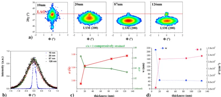
In order to further characterize lattice relaxation and to estimate the in-plane dislocation density in LSM, the in-plane lattice parameter a was measured on LSM/LAO (Figure 3a). The in-plane lattice parameter is very sensitive to the density of dislocations with Burgers vectors parallel to thefilm−substrate interface. Reciprocal space maps on LSM/LAO thinfilms were collected using aω angle of 0.25° and by collecting multiple ϕ scans while changing 2θχ in steps of 0.05°. Lattice parameters of LAO and LSM coincide in the case of the 10 nm thickfilm, and this confirms that the LSM layer is fully strained. The in-plane RSM shows that the LSM lattice parameter relaxes for thicker films (Figure 3a). The comparison of all LSM/LAO films is shown by the rocking curve graphs inFigure 3b. All the peaks in theϕ scans on the (200) plane of LSM layers thicker than 10 nm are broadened due to the strain relaxation. The calculated in-plane lattice parameters (a) and the ratio of out-of-plane to in-plane lattice parameters (c/a) as a function of thickness are shown in Figure 3c. The strain relaxation suggested by this thickness dependence has to involve generation of dislocation with in-plane Burgers vectors, such as interfacial misfit dislocations or edge dislocations in other planes of the thinfilms.
The in-plane dislocation density, δ*, in LSM films was estimated from the measured full width at half maximum (fwhm) of theΦ scans (rocking curves of (200) reflection) at the diffraction spot of LSM and was calculated using the following equation.38−40 δ*= b fwhm 4.35 2 2 (1)
Here,δ* is the dislocation density in the units of cm−1, and b is Burgers vector. In this case, b equals the lattice parameter of LSM along the (100) direction (3.898 Å). In obtaining the fwhm of rocking curves, the fwhm of the 10 nm thick LSM/
Figure 3. (a) In-plane reciprocal space mapping on LSM/LAOfilms. (b) Broadening of the rocking curves on LSM/LAO indicates relaxation of the in-plane lattice parameter with increasingfilm thickness. (c) In-plane lattice parameter and the ratio of out-of-plane to in-plane to parameters (c/a). Layers thicker than 20 nm indicate only slight lattice parameter variations with thickness. (d) Calculated density of dislocations (δ*) according toeq 1, and the average distance between adjacent dislocations (w) shows a significant change from 10 to 20 nm LSM thinfilms.
LAO was used to represent the diffractometer profile and, thus, was subtracted from the profiles of the thicker LSM thin films. The resulting density of dislocations, δ*, and the average separation distance between dislocations, w, are shown in
Figure 3d.δ* varies from 4.67 × 104cm−1for the 10 nmfilm
(i.e., w of nominally about 214 nm, largely limited by the instrument) to 2.29× 105cm−1(i.e., w of about 44 nm) for the 126 nmfilm.
In summary, from XRD and TEM analysis, we can conclude consistently that the LSM thinfilms are strained on STO and LAO substrates, and particularly on LAO, the strain release with increasing thickness involves generation of dislocations. The in-plane dislocation density is significantly increased above 10 nm thick LSM/LAOfilms.
These results can be well understood within the framework of a more general model on strain relaxation in thinfilms by the formation of dislocations. This model was also used to describe epitaxial thin film growth and dislocation propagation in semiconductors24,25,33,34and is in agreement with some papers dealing with dislocations in LSM.32,41−43It is based on the fact that during epitaxial (unrelaxed) growth of a thin film with lattice mismatch, a high strain energy develops. At a certain layer thickness, the strain energy becomes too high and formation of dislocations becomes energetically more favorable (other types of defects such as stacking faults and low-angle grain boundaries may also take part in the relaxation mechanism; however, these were not observed in our study). A critical thickness of 2.5 nm was reported for the LSM/LAO case.32The dislocation propagation mechanism for further layer growth was described in several publications.44−47It is generally assumed that dislocations start to nucleate either at the thin film surface or at the thin film/substrate interface (more favorable when the substrate has already many initial defects).48,49For a surface dislocation propagation mechanism, dislocation half-loops start at the surface and then expand in size, as shown inFigure 4a. These dislocation half-loops consist of two across-plane threading dislocations and an edge dislocation, which is largely parallel to the interface.
A dislocation half-loop represents the border of the additional or the missing lattice plane introduced for strain relaxation. However, this specific additional or missing plane
does not have to cover in the entirefilm cross section, rather its growth starts very locally. During further film growth, it then becomes broader. This is also indicated inFigure 4a. The four half-loops sketched there are not one and the same additional or missing plane shown for different times, but projections of four different half-loops (planes) that have started to grow for different film thicknesses. This also means that not all dislocations nucleate for the same film thickness, but some start growing for larger thicknesses. Furtherfilm growth thus leads to an increasing size and density of dislocation half-loops. Soon the number and size of half-loops becomes so high that they interact with each other, and also (interfacial) misfit dislocations begin to form. This further contributes to the strain relaxation. Finally, a whole array of extended misfit dislocations has developed, and the entirefilm becomes fully relaxed. This model of lattice relaxation by dislocations was verified for different thin film systems.24,25Similarly, for LSM on LAO, a recent study showed growth of misfit dislocation arrays.32
Since we observed lattice relaxation during film growth, assumption of the above-mentioned model of lattice relaxation by dislocation loops is plausible also for our layers. Moreover, the rocking curves of RSM measurements indicated a high density of in-plane dislocations, especially for thicker layers. However, even the thickest LSM layers used in this study are still not completely relaxed. This suggests that we still have a mixture of interfacial misfit dislocation arrays and dislocation half-loops, ending in some distance from the interface. This is sketched inFigure 4b; indication for both kinds of dislocations is also found in TEM (Figure 2). Completely relaxed layers should consist of the misfit dislocation array only, and a thickness of such relaxed layers can be rather large, for example, ca. 200 nm for BaTiO3on SrTiO3(lattice mismatch 2.2%).47
The observation of a substantial in-plane lattice parameter change between 10 and 20 nm layer thickness and the accompanying increase of the in-plane dislocation density indicates that the density of dislocation half-loops becomes particularly high in some distance from the LSM/LAO interface (Figure 2e). Threading dislocations of these dislocation half-loops are perpendicular to the interface and have their termination at the surface. Thus, they can contribute to perpendicular oxygen transport, and this effect was studied by
Figure 4. (a) Growth of dislocation half-loops starts at the surface; they become larger with increasingfilm thickness, and during interaction, they also grow to reach the substrate/thinfilm interface, thus forming misfit dislocations along the interface and threading dislocations across the thinfilm. (b) On the thin film surface, threading dislocations appear, and due to the different structure and chemical composition, they may cause a modified oxygen uptake and diffusion. The misfit dislocation array refers to the LSM/LAO interface.
tracer diffusion in this work. Existence of such perpendicular dislocations is also in agreement with the TEM measurements shown in Figure 2. Please note that the interfacial misfit
dislocation array of a fully relaxed layer does not have a perpendicular component of the Burgers vector and cannot lead to fast across-plane diffusion. However, misfit (or in-plane
Figure 5. (a) Typical18O tracer profiles measured on 40 nm LSM/LAO (red triangles) and LSM/STO (blue circles) are significantly different. For LSM/LAO, a pronounced tail in the profile is observed. Both near-surface regions are governed by diffusion through the bulk of LSM films (Db), whereas the substantial difference between the two profiles (marked by magenta shaded area) is due to diffusion along dislocations
(Dd). (b) Model with three domains (bulk, dislocations, and interface region) used to simulate the18O tracer diffusion profiles on LSM/LAO.
(c,d) Comparison of18O tracer profiles obtained for different thicknesses (d = 10−126 nm/140 nm) of LSM films on LAO (c) and on STO (d); they reveal some variation ofDbin LSM/LAO due to strain relaxation. (e) Effect of strain is also visible when plotting tracer profiles
obtained in the thinnest LSM layers (10 nm) on LAO and STO (DbLSM/STO≥ DbLSM/LAO). (f) Comparison of tracer profiles of the
thickest layers (126 nm/140 nm) on different substrates shows a large difference beyond the near surface zone.
edge) dislocations may still enable fast in-plane oxygen diffusion.
Ion Transport Properties of the LSM Films. Oxygen isotope 18O exchange experiments were performed at 600 °C
on all LSM films, and details on the exchange parameters are given in theMethodssection. Typical isotope depth profiles in LSM/STO and LSM/LAO are shown inFigure 5a for d = 40 nm. The isotope profiles on LAO and STO have a rapid decay close to the LSM surface. This part of the profile is attributed to (slow) bulk diffusion in LSM. Please note that these (bulk) profile widths are within the depth resolution of the instrument (cf. similar depth profiles found in ref19). For LSM on STO, the18O isotope fraction drops within thefirst 10 nm from 90% to values close to the natural abundance (0.205%). However, in LSM on LAO, after the first decay, there is a pronounced additional tail in the profile with a much slower decay toward the LSM/substrate interface. Hence, more than one diffusion mechanism has to play a role in these LSM/LAO films. The detailed analysis of LSM/STO films revealed also some deviations from a profile with only one diffusion process; cf. our first data on oxygen diffusion in epitaxial layers in ref 19
and profiles of LSM/STO shown in the Supporting Information (Figure S5), but the effects are much less pronounced compared to those of LSM/LAO.
The18O tracer profiles with two regimes were also observed
in columnar LSM layers,16,19where fast diffusion along grain boundaries leads to a long diffusion tail. However, in our epitaxial layers without grain boundaries (see Figure 2b,d,e), such a grain boundary diffusion path cannot explain the results. Therefore, other phenomena have to be responsible for the complex diffusion profile shape. It has already been shown in other studies that tensile or compressive lattice (elastic) strain may significantly increase or reduce the diffusion coefficient of oxygen in the bulk, for example, in (La,Sr)CoO3−δ(LSC)50or in La2NiO4+δ.
51
It was discussed above that thin LSMfilms on LAO are compressively strained. Moreover, dislocations are present in LSM on LAO. Hence, elastic strain as well as dislocations (plastic strain) may influence the diffusion profiles. In the following, we show that indeed both lattice strain and dislocations do affect the measured diffusion profiles in LSM, but the pronounced tail in Figure 5a is primarily due to fast diffusion along dislocations. Accordingly, data analysis was
performed by the model sketched inFigure 5b. This model is in agreement with the general considerations on thin film relaxation by dislocation growth (see above) and is discussed in more detail below.
The tracer profiles in LSM thin films with different thicknesses on STO and LAO substrates are given inFigure 5c,d. The variation of the thickness systematically changes the profiles in the LSM/LAO case. From the slope of the bulk related near-surface profile part, we already see that the bulk diffusion coefficient Db increases with layer thickness (i.e.,
relaxation of in-plane elastic compressive strain). The thinner LSM/LAO layers are more in-plane compressively strained and exhibit a lower Db. For LSM/STO, on the other hand, thickness
plays a smaller role. This variation of the bulk diffusion coefficient in LSM/LAO is in accordance with previous findings on Sr-doped LaCoO3−δ(LSC), where compressive lattice strain lowered the oxide ion conductivity.50The effect of strain can also be seen when comparing the tracer profiles of the thinnest LSMfilms (10 nm) on STO and LAO (Figure 5e); the in-plane compressively strained LSM/LAO shows a slightly steeper decay and thus a smaller bulk diffusion coefficient compared to the in-plane tensile strained LSM/STO (Db LSM/STO > Db LSM/LAO). This effect is largely gone for the thickest LSM films (126 nm/140 nm) on both substrates (Figure 5f, Db
LSM/STO ≈ Db LSM/LAO) in accordance with the
conclusion that those films are partially relaxed. However, in these partially relaxed 126 nm/140 nm thickfilms, the second diffusion regime becomes very pronounced for LSM/LAO (Figure 5f). Hence, the effects of lattice (elastic) strain can explain the near-surface parts of the profiles (Db) but cannot be the main reason for the second diffusion regime represented by the extended tail. We have noted above (Figure 3) that LSM/ LAO films develops dislocations upon relaxation of elastic strain. Therefore, we suggest oxygen diffusion along dis-locations as the origin of the second feature.
The followingfirst quantification of tracer profiles in LSM/ LAO thinfilms with different thickness gives further evidence that dislocations are highly relevant. The bulk related near-surface parts of the measured profile in Figure 6a (red line) were quantified with a single diffusion process, that is, by an error function, as shown by the violet line in Figure 6a. The entire experimental profiles and the fitted bulk profiles were
Figure 6. (a) Experimental18O isotope exchange depth profiles (red line) were fitted with a single bulk diffusion process (D
b) (violet line). (b)
Experimental andfitted profiles were integrated (∫ (18O),∫ (18O)bulk). The ratio of the integrals∫ (18O)bulk)/(∫ (18O) strongly decreases
with increasing LSMfilm thickness; the thinnest LSM film has the lowest contribution of dislocations. The extrapolation of ∫ (18O)bulk)/
then integrated. The areas beneath both curves represent the tracer amount incorporated by bulk diffusion only and by both bulk and second (dislocation) diffusion processes. The importance of the second diffusion part can then be estimated from the ratios of the integrals (∫ (18O)bulk/∫ (18O)), and this
ratio is plotted as a function of layer thickness inFigure 6b. The ∫ (18O)
bulk/∫ (18O) ratio decreases with increasing LSM
thickness (Figure 6b, blue line), and hence, the contribution of the second diffusion part increases with increasing LSM film thickness. From an extrapolation of this curve, wefind that for a thickness of 2.8 nm,∫ (18O)
bulk/∫ (18O) is equal to 1 (absence
of a second diffusion regime, only bulk diffusion prevails). The number of dislocations in epitaxial layers generally increases with layer thickness, and dislocations begin to appear in layers above a critical relaxation thickness, dc. For LSMfilms on LAO single crystal, this critical thickness was experimentally determined to be 2.5 nm,32 and according to theoretical calculations, it is 1.7 nm.32 This is in rather good agreement with the critical thickness of 2.8 nm estimated from our integral analysis of the tracer profiles. The increased importance of the second diffusion process with increasing film thickness and the consistency of the critical thickness in LSMfilms deduced from our tracer integral analysis with that deduced from previous structural characterization of LSM films32 support our interpretation that the second part of the diffusion profiles is caused by oxygen diffusion along dislocations.
Based on these observations and the general considerations of dislocation growth in thin films (see above), we can construct afinite element model for quantitatively analyzing the measured profiles (seeFigure 5b). Diffusion along dislocations is usually described by a pipe with different diffusion properties.52 The across-plane threading dislocations of the supposed dislocation half-loops (cf. Figure 4b) are therefore represented by a pipe perpendicular to the surface. At a certain depth (at latest at the LSM/LAO interface), this pipe is deflected to an in-plane edge dislocation. Adding such in-plane pipes to the model geometry would lead to an over-parameterization of our fit procedure as their effect on the entire profile might be rather small. Hence, those are not included in the model. Still, the deflection of the dislocation half-loop is in agreement with the existence of an interfacial region without fast across-plane dislocation diffusion, which we have to introduce into our model for an accurate data analysis; see below.
Hence, our model includes a bulk region with diffusion coefficient Dband oxygen exchange coefficient kb, as well as a
pipe-like dislocation with different diffusion and oxygen exchange coefficients, Dd and kd (Figure 5b). The density of dislocations, δ, determines their separation distance, w = 1/δ. The dislocation core radius, r, can be estimated according to f/ (1− ν),53,54where f is the plane spacing perpendicular to the slip plane and ν is Poisson’s ratio. In studies on dislocations,55,56f is considered to vary from b to 4b, where b is Burgers vector. For the sake of simplicity, the dislocation core radius wasfixed to 1 nm in our analysis. The LAO substrate is assumed to be ion blocking.
Results of finite element model calculations without a dislocation-free interfacial zone are shown as an example for the profile measured on 87 nm LSM/LAO (Figure 7). An isotope depth profile with only a single (bulk) diffusion process in the LSM film can quantitatively describe the near-surface part of the profile. The calculated Dband kbare similar to those found in our previous study on nanocrystalline LSM films19 (see
Figure S6). Finite element calculations including the con-tribution of the dislocations are shown inFigure 7(blue line) and reproduce a large part of the measured profile. Please note that the high tracer fraction in the center part of the film requires fast tracer diffusion in the dislocation but largely reflects the tracer ions that have leaked from the dislocation into the bulk (cf. the diffusion tail of fast grain boundary diffusion observed in the so-called Harrison-type B case).57
In these calculated profiles, the dislocation diffusion coefficient is mainly reflected by the slope of the second part of the profile (see alsoFigure S7c). The dislocation exchange coefficient (kd) and the dislocation density (δ) primarily affect
the absolute value of the tracer fraction in the second part of the profile. However, since their effects on the profile are similar (Figure S7b,c), they cannot be obtained independently from such a data analysis. This is discussed in more details in the Supporting Information (Figure S7). Fortunately, the resulting value of Ddis hardly affected by the exact choice of kd
andδ. The estimated dislocation densities inFigure 3d refer to both the edge and misfit dislocation, whereas, here, we have to take only the yet-unknown density of the out-of-plane threading dislocations. Hence, for the sake of simplicity, a fixed kd value was chosen for quantifying all measured 18O
tracer depth profiles, and then the dislocations density and Dd
were adjusted asfit parameters.
The strong tracer fraction decay close to the LSM/LAO interface (but still within LSM) indicates the existence of a further region with different diffusion properties, and the sharpness of the decay suggests a locally lower diffusion coefficient. A similar effect was found in ref 51for La2NiO4+δ
epitaxial thinfilms. This additional LSM interfacial region was observed for allfilms thicker than 10 nm, and it could be well described by a thin layer with a thicknessΔiof typically 10−25 nm (Table 1) and a homogeneous diffusion coefficient, Di(i.e.,
without fast diffusion along dislocations, cf. Figure 5b). Even though other effects may also contribute, this layer might simply be caused by the ending of most dislocation loops in some depth (seeFigure 4), in accordance with the experimental observation that the interface zone has more in-plane compressive lattice strain and less dislocations (Figure 2e).
Figure 7. Experimental18O tracer profile of a 87 nm thick LSM/
LAOfilm (green circles) was fitted with a model including only bulk contribution (orange line) and a model including bulk and dislocation contribution (blue line). However, to completely describe the experimental profile, an additional contribution arising from the in-plane compressively strained interface region must be included (red line).
Altogether, thefinite element model thus has to consist of three domains (bulk, dislocation, and interfacial part), and the finite element calculations were performed with five free parameters: Db, kb, Dd, Di, andδ = 1/w (kdwasfixed at 7.0 × 10⁻¹¹ m·s−1; see above). All parameters resulting from this numerical approximation to the measured data are summarized in Figure 8a and Table 1. Only for the 10 nm film, the dislocation-related profile part was not sufficiently developed for quantification.
Most importantly, the diffusion of oxygen along the dislocations turns out to be much faster than bulk diffusion. For thick layers, diffusion along dislocations is more than 3 orders of magnitude faster than bulk diffusion. The estimated Ddvalues seem to depend on thefilm thickness (seeFigure 8a), and reasons are not clear yet. Some lateral variations may be present, as indicated by the three different positions shown in
Figure 8b for a 40 nm LSMfilm. However, one also has to keep in mind that the dislocation-related curve part is rather short for thin layers, and its slope depends less than linear on Dd, similar to the square root dependence between inverse slope and grain boundary diffusion coefficient in the case of fast grain boundary diffusion. Hence, also the accuracy of the Ddvalues is lower for
thin films. Moreover, we may have a depth-dependent threading dislocation density, even for a given thickness (cf.
Figure 4), which was not considered in the model. (Please note, the short tracer profile in LAO is most probably a SIMS artifact due to intermixing during sputtering; the natural abundance level was quickly reached, in accordance with the very low tracer diffusion coefficient in the ionically blocking LAO.)
Bulk diffusion coefficients in LSM/LAO increase only by about a factor of 2 for thicker layers (strain effect, cf. qualitative discussion ofFigure 5c), and the dislocation densityδ required to reproduce the results for the given kdvaried between 1.4.×
105and 3.3× 105cm−1for thefilms of 20−126 nm. Despite the
uncertainty of the kd value, we believe that most probably oxygen incorporation into the dislocations is also faster than that into the bulk, in accordance with differences found for grain boundaries in LSM.19
As already mentioned above, in-plane edge dislocations of dislocation half-loops as well as interfacial misfit dislocations are not included in our fit model. However, possibly we see the effect of in-plane dislocations of half-loops as the hump before the sharp tracer decrease in the interfacial region (Figure 7). Probably a large number of in-plane edge dislocations exist close to the interface due to onset of dislocation growth after exceeding a certain critical length. Across-plane tracer diffusion thus becomes deflected to the horizontal direction at this depth. Hence, the perpendicular leakage of tracer ions from the fast
Dband kbare the bulk diffusion and surface exchange coefficient in LSM bulk; Ddand kdare the diffusion and surface exchange coefficient through
dislocations; Diis the diffusion in the interface zone; Δiis the interfacial layer thickness, andδ is the dislocation density.
Figure 8. (a) Diffusion coefficients in bulk and along dislocations, DbandDd, obtained byfinite element modeling of the experimentally
measured18O depth profiles, as a function of LSM film thickness on LAO substrate. (b)18O tracer depth profiles obtained on the same sample
but for different measurement positions. Dbis constant at each sampled position, whereas the dislocation related part (Dd) varies among
dislocation into the bulk increases the local tracer fraction in this plane, and a tracer fraction hump may result.
In order to support our interpretation of only partly relaxed LSM/LAO films in their as-deposited conditions, with dislocation half-loops largely ending in some depth before the interface, we performed the following experiment. We annealed 40 nm thick LSMfilms at 1000 °C for 3 h and again performed a tracer exchange experiment with subsequent SIMS analysis. AFM images indicate pronounced smoothening of the surface (Figure 9a−c), probably due to further lattice relaxation.Figure 9d,e displays the diffusion profile on the annealed LSM/STO and LSM/LAO and, for comparison, also the profile obtained on the as-deposited LSM/LAO. Clearly, and interestingly, the tail reflecting fast dislocation diffusion across the LSM/LAO film is largely gone after this annealing step, but the interfacial hump strongly increases. This is exactly what one would expect when the layer further relaxes upon annealing: after annealing, the dislocation half-loops grow and interact, leading to an extended in-plane misfit dislocation array at the interface, but much less dislocation half-loops remain. Then the fast across-plane diffusion process becomes less pronounced, but fast in-plane diffusion in the numerous interfacial misfit dislocations may cause a significant diffusion hump (see sketch inFigure 9f).
In general, faster diffusion through dislocations can be explained either by a higher vacancy concentration or by a higher mobility of oxygen vacancies in the dislocation region. In our case, we think that a higher oxygen vacancy concentration
is more feasible due to the different chemical composition that may surround the dislocation, for example, due to possible Sr segregation in the vicinity of a dislocation, which would cause a higher vacancy concentration, as known from the studies of Sr doping in LaMnO3.58An elastic strainfield coupling to solute
concentration is known to produce dislocation-driven impurity segregation.20,59−62Two recent studies42,43 on dislocations in LSM thinfilms on LAO substrates have experimentally shown by electron energy loss spectroscopy that the dislocation core is terminated with Mn columns and an extra atomic plane of La/ Sr columns. It was found that Mn at the dislocation core occupies the La site and thus forms antisite defects.42Also, a higher oxygen vacancy concentration in the dislocation core region was observed,42,63which is in a good agreement with our study.
CONCLUSIONS
In summary, we have assessed oxygen ion diffusion in epitaxial thin LSMfilms on LAO and STO single-crystal substrates and particularly the effect of dislocations on this diffusion. XRD and reciprocal space mapping showed that both LSM/LAO and LSM/STO are strained and relax with increased layer thickness from 10 nm to more than 100 nm. Particularly for LSM/LAO, generation of dislocations accompany strain relaxation, confirmed by in-plane RSM and TEM. Measured 18O tracer
depth profiles show a pronounced difference between LSM/ LAO and LSM/STO. First, the LSM bulk diffusion coefficient Dbin LSM/LAO is slightly lower than that for LSM/STO (for
Figure 9. Surface topography probed by AFM on both LSM/LAO (b) and LSM/STO (c) samples annealed at 1000°C and on as-prepared LSM/LAO (a). This shows that annealed layers became smoother with a pronounced terrace-like surface. Isotope exchange depth profiles reveal a hump at the interface that can be explained by the fast oxygen diffusion along in-plane misfit dislocations (f).
dislocations is about 2−3 orders of magnitude faster than that in the bulk. Close to the LSM/LAO interface, diffusion becomes again much slower, possibly due to the absence of many threading dislocations in this region. Annealing of the LSM/LAO film to relax it further caused annihilation of threading dislocations and strongly reduced the across-plane diffusion.
The faster oxygen diffusion along dislocations in LSM is different from the behavior in SrTiO38−11 and Gd-doped
ceria,20where dislocations did not provide fast diffusion paths. The reason for this difference might be the significant reducibility of LSM accompanied by ease of Sr segregation possibly causing Mn antisite defects and by the absence of any significant space charge effects in LSM. The promoting effect of dislocations on oxygen ion transport and surface exchange kinetics revealed here could be important for tuning the kinetic properties of a broad range of reducible ionic and mixed conducting oxides which do not form detrimental space charge zones.
METHODS
LSM thinfilms were prepared by pulsed laser deposition (PLD). The PLD target was produced from La0.8Sr0.2MnO3 (Sigma-Aldrich)
powder, which was isostatically pressed into pellets and sintered for 12 h at 1200°C in air. Thin LSM films were prepared on SrTiO3
(STO) (100) (CrysTec GmbH, Germany) and LaAlO3(LAO) (100)
(CrysTec GmbH, Germany) single crystals with varied layer thickness. Deposition was performed under 1.3× 10⁻²mbar oxygen pressure at 650°C using a KrF excimer laser with a wavelength of 248 nm and a pulse frequency of 10 Hz. The laser beam energy was set to 400 mJ per pulse and a target−substrate distance of 7 cm with a cooling rate of 5 °C/min.
The thickness of the LSM layers was controlled by deposition time and later determined by transmission electron microscopy (FEI TECNAI F20) from cross-section images and SIMS depth profiles and resulted in the following values (TEM values with errors): 10± 1, 20 nm, 40± 3, 87 ± 2, and 126 ± 3 nm for LSM on LAO and 10 ± 1, 20, 40± 3, 92, and 140 nm for LSM on STO. The surface morphology was characterized by atomic force microscopy using Veeco/Digital Instrument Nanoscope IV. The AFM images were processed using the Nanoscope software version 5.31R1 (Digital Instruments).
X-ray diffraction 2θ−ω scans, RSM, and in-plane RSM of epitaxial layers were performed with a high-resolution four-circle Bruker D8 Discover diffractometer, which is equipped with a Göbel mirror, four-bounce Ge(220) channel-cut monochromator, Eulerian cradle, and a scintillation counter, using Cu Kα1 radiation. The thickness of the thinnest epitaxial layers was also analyzed by X-ray reflectivity (XRR) measurements performed on Rigaku Smartlab diffractometer equipped with two-bounce Ge(220) channel-cut monochromator using Cu Kα1 radiation. From XRR measurements (not shown), the thickness of these epitaxial layers was again found to be 10, 20, and 40 nm.
quenched to room temperature with a cooling rate of 100°C/min. Some additional exchange experiments were performed in a temperature ranging from 400 to 800 °C (the results are shown in theSupporting Information).
The resulting18O depth profiles were subsequently investigated by
time-of-flight secondary ion mass spectrometry (ToF-SIMS) (ION-TOF GmbH, Germany ToF-SIMS 5). SIMS measurements were performed in the collimated burst alignment mode with Bi3++primary
ions (25 keV), which allows accurate determination of 18O
concentrations in a broad intensity range. Negative secondary ions were analyzed in areas of 70× 70 μm2, using a raster of 512× 512
measurement points. For the sputtering of material, 2 keV Cs+ions
were applied with a sputter crater of 350× 350 μm2and sputtering ion current of 50 nA. The charging of surfaces was compensated by an electron flood gun. The depth profiles of isotope fraction (f(18O))
were obtained by normalizing integrated intensities I of18O and16O
according to + f I I I ( O) ( O) ( O) ( O) 18 18 16 18 (2) ASSOCIATED CONTENT
*
S Supporting InformationThe Supporting Information is available free of charge on the
ACS Publications websiteat DOI:10.1021/acsnano.7b06228. Details on thin film surface topography, further TEM images with more detailed analysis, additional tracer depth profiles, and further finite element calculations (Figures S1−S7) (PDF) AUTHOR INFORMATION Corresponding Authors *E-mail:[email protected]. *E-mail:j.fl[email protected]. ORCID Edvinas Navickas:0000-0003-4217-401X Yan Chen:0000-0001-6193-7508 Present Address ¶
New Energy Institute, School of Environment and Energy, South China University of Technology, 382 East Road, University City, Guangzhou 510006, P.R. China.
Notes
The authors declare no competingfinancial interest.
ACKNOWLEDGMENTS
The authors from Vienna University of Technology gratefully acknowledge Austrian Science Fund (FWF) (Projects F4509-N16 and F4501-F4509-N16) for the financial support. The authors
from MIT gratefully acknowledge the DOE-Basic Energy Sciences, Grant No. DE-SC0002633, for financial support. T.M.H. also acknowledgesfinancial support from the Progress-100 program at Kyushu University.
REFERENCES
(1) Chen, K. X.; Dai, Q.; Lee, W.; Kim, J. K.; Schubert, E. F.; Grandusky, J.; Mendrick, M.; Li, X.; Smart, J. A. Effect of Dislocations on Electrical and Optical Properties of n-Type Al0.34Ga0.66N. Appl.
Phys. Lett. 2008, 93, 192108.
(2) Weimann, N. G.; Eastman, L. F.; Doppalapudi, D.; Ng, H. M.; Moustakas, T. D. Scattering of Electrons at Threading Dislocations in GaN. J. Appl. Phys. 1998, 83, 3656−3659.
(3) Look, D. C.; Sizelove, J. R. Dislocation Scattering in GaN. Phys. Rev. Lett. 1999, 82, 1237−1240.
(4) Williams, G. P.; Slifkin, L. Diffusion Along Dislocations. Phys. Rev. Lett. 1958, 1, 243−244.
(5) Shima, Y.; Ishikawa, Y.; Nitta, H.; Yamazaki, Y.; Mimura, K.; Isshiki, M.; Iijima, Y. Self-Diffusion Along Dislocations in Ultra High Purity Iron. Mater. Trans. 2002, 43, 173−177.
(6) Legros, M.; Dehm, G.; Arzt, E.; Balk, T. J. Observation of Giant Diffusivity Along Dislocation Cores. Science 2008, 319, 1646−1649.
(7) Curtin, W. A.; Olmsted, D. L.; Hector, L. G. A Predictive Mechanism for Dynamic Strain Ageing in Aluminium-Magnesium Alloys. Nat. Mater. 2006, 5, 875−880.
(8) Waldow, S. P.; De Souza, R. A. Computational Study of Oxygen Diffusion along a[100] Dislocations in the Perovskite Oxide SrTiO3.
ACS Appl. Mater. Interfaces 2016, 8, 12246−12256.
(9) Marrocchelli, D.; Sun, L.; Yildiz, B. Dislocations in SrTiO3: Easy
to Reduce but Not so Fast for Oxygen Transport. J. Am. Chem. Soc. 2015, 137, 4735−4748.
(10) Metlenko, V.; Ramadan, A. H. H.; Gunkel, F.; Du, H.; Schraknepper, H.; Hoffmann-Eifert, S.; Dittmann, R.; Waser, R.; De Souza, R. A. Do Dislocations Act as Atomic Autobahns for Oxygen in the Perovskite Oxide SrTiO3? Nanoscale 2014, 6, 12864−12876.
(11) Adepalli, K. K.; Yang, J.; Maier, J.; Tuller, H. L.; Yildiz, B. Tuller and Bilge Yildiz, Tunable Oxygen Diffusion and Electronic Conduction in SrTiO3 by Dislocation-induced Space Charge Fields.
Adv. Funct. Mater. 2017, 27, 1700243.
(12) Murphy, S. T.; Jay, E. E.; Grimes, R. W. Pipe Diffusion at Dislocations in UO2. J. Nucl. Mater. 2014, 447, 143−149.
(13) Nakagawa, T.; Nakamura, A.; Sakaguchi, I.; Shibata, N.; Lagerlof, K. P. D.; Yamamoto, T.; Haneda, H.; Ikuhara, Y. Oxygen Pipe Diffusion in Sapphire Basal Dislocation. J. Ceram. Soc. Jpn. 2006, 114, 1013−1017.
(14) Fleig, J.; Maier, J. Local Conductivitiy Measurements on AgCl Surfaces Using Microelectrodes. Solid State Ionics 1996, 85, 9−15.
(15) Yan, L.; Salvador, P. A. Substrate and Thickness Effects on the Oxygen Surface Exchange of La0.7Sr0.3MnO3 Thin Films. ACS Appl.
Mater. Interfaces 2012, 4, 2541−2550.
(16) Saranya, A. M.; Pla, D.; Morata, A.; Cavallaro, A.; Canales-Vázquez, J.; Kilner, J. A.; Burriel, M.; Tarancón, A. Engineering Mixed Ionic Electronic Conduction in La0.8Sr0.2MnO3+δ Nanostructures
through Fast Grain Boundary Oxygen Diffusivity. Adv. Energy Mater. 2015, 5, 1500377.
(17) Usiskin, R. E.; Maruyama, S.; Kucharczyk, C. J.; Takeuchi, I.; Haile, S. M. Probing the Reaction Pathway in (La0.8Sr0.2)0.95MnO3+δ
Using Libraries of Thin Film Microelectrodes. J. Mater. Chem. A 2015, 3, 19330−19345.
(18) Chiabrera, F.; Morata, A.; Pacios, M.; Tarancón, A. Insights into the Enhancement of Oxygen Mass Transport Properties of Strontium-Doped Lanthanum Manganite Interface-Dominated Thin Films. Solid State Ionics 2017, 299, 70−77.
(19) Navickas, E.; Huber, T. M.; Chen, Y.; Hetaba, W.; Holzlechner, G.; Rupp, G.; Stoger-Pollach, M.; Friedbacher, G.; Hutter, H.; Yildiz, B.; Fleig, J. Fast Oxygen Exchange and Diffusion Kinetics of Grain Boundaries in Sr-Doped LaMnO3Thin Films. Phys. Chem. Chem. Phys.
2015, 17, 7659−7669.
(20) Sun, L.; Marrocchelli, D.; Yildiz, B. Edge Dislocation Slows Down Oxide Ion Diffusion in Doped CeO2by Segregation of Charged
Defects. Nat. Commun. 2015, 6, 6294.
(21) Huber, T. M.; Kubicek, M.; Opitz, A. K.; Fleig, J. The Relevance of Different Oxygen Reduction Pathways of La0.8Sr0.2MnO3 (LSM)
Thin Film Model Electrodes. J. Electrochem. Soc. 2015, 162, F229− F242.
(22) Fleig, J. Solid Oxide Fuel Cell Cathodes: Polarization Mechanisms and Modeling of the Electrochemical Performance. Annu. Rev. Mater. Res. 2003, 33 (1), 361−382.
(23) Adler, S. B. Factors Governing Oxygen Reduction in Solid Oxide Fuel Cell Cathodes. Chem. Rev. 2004, 104, 4791−4844.
(24) Sun, H. P.; Tian, W.; Pan, X. Q.; Haeni, J. H.; Schlom, D. G. Evolution of Dislocation Arrays in Epitaxial BaTiO3Thin Films Grown
on (100) SrTiO3. Appl. Phys. Lett. 2004, 84, 3298−3300.
(25) Sun, H. P.; Pan, X. Q.; Haeni, J. H.; Schlom, D. G. Structural Evolution of Dislocation Half-Loops in Epitaxial BaTiO3 Thin Films
During High-Temperature Annealing. Appl. Phys. Lett. 2004, 85, 1967−1969.
(26) Haghiri-Gosnet, A. M.; Wolfman, J.; Mercey, B.; Simon, C.; Lecoeur, P.; Korzenski, M.; Hervieu, M.; Desfeux, R.; Baldinozzi, G. Microstructure and Magnetic Properties of Strained La0.7Sr0.3MnO3
Thin Films. J. Appl. Phys. 2000, 88, 4257−4264.
(27) Haghiri-Gosnet, A. M.; Renard, J. P. CMR Mmanganites: Physics, Thin Films and Devices. J. Phys. D: Appl. Phys. 2003, 36, R127.
(28) Santiso, J.; Roqueta, J.; Bagués, N.; Frontera, C.; Konstantinovic, Z.; Lu, Q.; Yildiz, B.; Martínez, B.; Pomar, A.; Balcells, L.; Sandiumenge, F. Self-Arranged Misfit Dislocation Network Formation upon Strain Release in La0.7Sr0.3MnO3/LaAlO3(100) Epitaxial Films
under Compressive Strain. ACS Appl. Mater. Interfaces 2016, 8, 16823−16832.
(29) Sheng, Z. G.; Sun, Y. P.; Zhu, X. B.; Zhao, B. C.; Ang, R.; Song, W. H.; Dai, J. M. In Situ Growth of -Axis-Oriented Thin Films on Si(001). Solid State Commun. 2007, 141, 239−242.
(30) Grande, T.; Tolchard, J. R.; Selbach, S. M. Anisotropic Thermal and Chemical Expansion in Sr-Substituted LaMnO3+δ: Implications for
Chemical Strain Relaxation. Chem. Mater. 2012, 24, 338−345. (31) Jiang, J. C.; Pan, X. Q. Microstructure and Growth Mechanism of Epitaxial SrRuO3Thin Films on (001) LaAlO3Substrates. J. Appl.
Phys. 2001, 89, 6365−6369.
(32) Yeh, W.; Matsumoto, A.; Sugihara, K.; Hayase, H. Sputter Epitaxial Growth of Flat Germanium Film with Low Threading-Dislocation Density on Silicon (001). ECS J. Solid State Sci. Technol. 2014, 3, Q195−Q199.
(33) Speck, J. S.; Rosner, S. J. The Role of Threading Dislocations in the Physical Properties of GaN and its Alloys. Phys. B 1999, 273, 24− 32.
(34) Tarantini, C.; Kametani, F.; Lee, S.; Jiang, J.; Weiss, J. D.; Jaroszynski, J.; Hellstrom, E. E.; Eom, C. B.; Larbalestier, D. C. Development of Very High Jcin Ba(Fe1‑xCox)2As2Thin Films Grown
on CaF2. Sci. Rep. 2015, 4, 7305.
(35) Garbrecht, M.; Saha, B.; Schroeder, J. L.; Hultman, L.; Sands, T. D. Dislocation-Pipe Diffusion in Nitride Superlattices Observed in Direct Atomic Resolution. Sci. Rep. 2017, 7, 46092.
(36) Chen, A.; Bi, Z.; Jia, Q.; MacManus-Driscoll, J. L.; Wang, H. Microstructure, Vertical Strain Control and Tunable Functionalities in Self-Assembled, Vertically Aligned Nanocomposite Thin Films. Acta Mater. 2013, 61, 2783−2792.
(37) Metzger, T.; Höpler, R.; Born, E.; Ambacher, O.; Stutzmann, M.; Stömmer, R.; Schuster, M.; Göbel, H.; Christiansen, S.; Albrecht, M.; Strunk, H. P. Defect Structure of Epitaxial GaN Films Determined by Transmission Electron Microscopy and Triple-Axis X-ray Diffractometry. Philos. Mag. A 1998, 77, 1013−1025.
(38) Zhai, Z. Y.; Wu, X. S.; Cai, H. L.; Lu, X. M.; Hao, J. H.; Gao, J.; Tan, W. S.; Jia, Q. J.; Wang, H. H.; Wang, Y. Z. Dislocation Density and Strain Distribution in SrTiO3 Film Grown on (1 1 0) DyScO3
Substrate. J. Phys. D: Appl. Phys. 2009, 42, 105307.
(44) Ihli, J.; Clark, J. N.; Côté, A. S.; Kim, Y.-Y.; Schenk, A. S.; Kulak, A. N.; Comyn, T. P.; Chammas, O.; Harder, R. J.; Duffy, D. M.; Robinson, I. K.; Meldrum, F. C. Strain-Relief by Single Dislocation Loops in Calcite Crystals Grown on Self-Assembled Monolayers. Nat. Commun. 2016, 7, 11878.
(45) Hull, R.; Bean, J. C. Misfit Dislocations in Lattice-Mismatched Epitaxial Films. Crit. Rev. Solid State Mater. Sci. 1992, 17, 507−546.
(46) Suzuki, T.; Nishi, Y.; Fujimoto, M. Analysis of Misfit Relaxation in Heteroepitaxial BaTiO3Thin Films. Philos. Mag. A 1999, 79, 2461−
2483.
(47) Jain, S. C.; Decoutere, S.; Willander, M.; Maes, H. E. SiGe HBTs for Application in BiCMOS Technology: I. Stability, Reliability and Material Parameters. Semicond. Sci. Technol. 2001, 16, R51.
(48) Jesser, W. A.; Fox, B. A. On the Generation of Misfit Dislocations. J. Electron. Mater. 1990, 19, 1289−1297.
(49) Saranya, A. M.; Pla, D.; Morata, A.; Cavallaro, A.; Canales-Vázquez, J.; Kilner, J. A.; Burriel, M.; Tarancón, A. Engineering Mixed Ionic Electronic Conduction in La0.8Sr0.2MnO3+δ Nanostructures
through Fast Grain Boundary Oxygen Diffusivity. Adv. Energy Mater. 2015, 5, 1500377.
(50) Kubicek, M.; Cai, Z.; Ma, W.; Yildiz, B.; Hutter, H.; Fleig, J. Tensile Lattice Strain Accelerates Oxygen Surface Exchange and Diffusion in La1−xSrxCoO3−δThin Films. ACS Nano 2013, 7, 3276−
3286.
(51) Burriel, M.; Garcia, G.; Santiso, J.; Kilner, J. A.; Chater, R. J.; Skinner, S. J. Anisotropic Oxygen Diffusion Properties in Epitaxial Thin Films of La2NiO4+δ. J. Mater. Chem. 2008, 18, 416−422.
(52) Claire, A. D. L.; Rabinovitch, A. A Mathematical Analysis of Diffusion in Dislocations. I. Application to Concentration’Tails’. J. Phys. C: Solid State Phys. 1981, 14, 3863.
(53) Peierls, R. The Size of a Dislocation. Proc. Phys. Soc. 1940, 52, 34.
(54) Nabarro, F. R. N. Dislocations in a Simple Cubic Lattice. Proc. Phys. Soc. 1947, 59, 256.
(55) Gutkin, M. Y.; Aifantis, E. C. Edge Dislocation in Gradient Elasticity. Scr. Mater. 1997, 36, 129−135.
(56) Payne, A. P.; Lairson, B. M.; Clemens, B. M. Strain Relaxation in Ultrathin Films: A Modified Theory of Misfit-Dislocation Energetics. Phys. Rev. B: Condens. Matter Mater. Phys. 1993, 47, 13730−13736.
(57) Harrison, L. G. Influence of Dislocations on Diffusion Kinetics in Solids with Particular Reference to the Alkali Halides. Trans. Faraday Soc. 1961, 57, 1191−1199.
(58) Mebane, D. S.; Liu, Y.; Liu, M. Refinement of the Bulk Defect Model for LaxSr1−xMnO3±δ. Solid State Ionics 2008, 178, 1950−1957.
(59) Spicer, J. B. Nonlinear Effects on Impurity Segregation in Edge Dislocation Strain Fields. Scr. Mater. 2008, 59, 377−380.
(60) Du, H.; Jia, C.-L.; Houben, L.; Metlenko, V.; De Souza, R. A.; Waser, R.; Mayer, J. Atomic Structure and Chemistry of Dislocation Cores at Low-Angle Tilt Grain Boundary in SrTiO3 Bicrystals. Acta
Mater. 2015, 89, 344−351.
(61) Blavette, D.; Cadel, E.; Fraczkiewicz, A.; Menand, A. Three-Dimensional Atomic-Scale Imaging of Impurity Segregation to Line Defects. Science 1999, 286, 2317−2319.