in terahertz quantum-cascade lasers
The MIT Faculty has made this article openly available.
Please share
how this access benefits you. Your story matters.
Citation
Kumar, Sushil, and Qing Hu. “Coherence of Resonant-tunneling
Transport in Terahertz Quantum-cascade Lasers.” Physical Review
B 80.24 (2009). © 2009 The American Physical Society
As Published
http://dx.doi.org/ 10.1103/PhysRevB.80.245316
Publisher
American Physical Society
Version
Final published version
Citable link
http://hdl.handle.net/1721.1/71881
Terms of Use
Article is made available in accordance with the publisher's
policy and may be subject to US copyright law. Please refer to the
publisher's site for terms of use.
Coherence of resonant-tunneling transport in terahertz quantum-cascade lasers
Sushil Kumar and Qing Hu
Department of Electrical Engineering and Computer Science and Research Laboratory of Electronics, Massachusetts Institute of Technology, Cambridge, Massachusetts 02139, USA
共Received 23 July 2009; revised manuscript received 6 October 2009; published 15 December 2009兲
We develop simple density-matrix models to describe the role of coherence in resonant-tunneling共RT兲 transport of quantum-cascade lasers 共QCLs兲. Specifically, we investigate the effects of coherent coupling between the lasing levels with other levels on the transport properties and gain spectra. In the first part of the paper, we use a three-level density-matrix model to obtain useful analytical expressions for current transport through the injector barrier in a QCL. An expression for the slope discontinuity in the current-voltage charac-teristics at the lasing threshold is derived. This value is shown to be a direct measure of the population inversion at threshold and contradicts the previously held belief of it being indicative of ratio of the laser level lifetimes. In the second part of the paper, we use density matrices to compute the gain spectrum for a resonant-phonon terahertz QCL design. The large anticrossing of the doublet of lower radiative levels is reflected in a broad gain linewidth due to a coherent RT assisted depopulation process. At certain bias condi-tions, the gain spectrum exhibits double peaks which is supported by experimental observations.
DOI:10.1103/PhysRevB.80.245316 PACS number共s兲: 73.63.⫺b, 78.67.Pt, 05.60.Gg, 42.55.Px
I. INTRODUCTION
The role of sequential resonant tunneling 共RT兲 in semi-conductor quantum wells for charge transport1 as well as
light amplification2has been discussed since the early 1970s.
Subsequently, multiple proposals were introduced in the 1980s to predict intersubband lasing in semiconductor super-lattice structures. With the advent of a unique RT based charge injection scheme, a unipolar mid-infrared 共IR兲 inter-subband laser, the so-called quantum-cascade laser 共QCL兲, was first demonstrated in 1994.3 Mid-IR QCLs have since undergone rapid progress and room-temperature continuous-wave 共cw兲 operation is now obtained over the ⬃4–10 m spectrum. Based on similar design principles, the operating frequency range of these devices has also been extended to terahertz frequencies 共⬃1–5 THz and ⬃60–300 m兲.4 However, due to additional challenges
associated with the charge transport in these low-frequency devices, terahertz QCLs are still required to be cryogenically cooled.5–7 It then becomes increasingly important to better
understand the transport processes in terahertz QCLs to im-prove the existing designs, with a goal to ultimately achieve room-temperature operation.
The best temperature performance for terahertz QCLs is obtained with the resonant-phonon 共RP兲 designs,8,9 and
op-eration up to 186 K without magnetic field10and 225 K with
magnetic field11 has been demonstrated. For QCLs, almost
universally across all different designs and operating fre-quencies, RT plays an important role in the electrical injec-tion process to populate the upper radiative level.12,13For the resonant-phonon terahertz QCLs共RPTQCLs兲, RT also plays an important role in the lower-level depopulation. Newer de-signs with RT based extraction have also been demonstrated recently achieving very low threshold current densities.14,15
The radiative levels in a terahertz QCL have small energy separation in the range ofប⬃4–20 meV 共⬃1–5 THz兲. The potential barriers in the multiple quantum-well 共QW兲 structure are therefore kept thick to obtain tightly coupled
levels in order to maintain selectivity of the injection as well as the depopulation processes. This makes the coupling en-ergies共as characterized by the anticrossing energy 2ប⍀ijfor
the coupled levels i and j兲 similar in value to the low-temperature energy-level broadening, which is expected to be on the order of a few millielectronvolt. Consequently, the loss of coherence 共or dephasing兲 in the RT process has a significant bearing on the electron transport across the barriers.16
In this paper, simple density-matrix 共DM兲 models are used to incorporate the important role of coherence in the RT transport of QCLs. We consider the case of tight binding for intermodule transport since the intermodule energy anticross-ings 2ប⍀ij are typically much smaller than the intramodule
energy-level separations, where each module can consist of one or more QWs and the QCL structure is a periodic rep-etition of one or more such modules. In the first part of the paper, we use a density-matrix model similar to the two-level model first proposed by Kazarinov and Suris17and then later
also discussed in Refs. 12, 18, and 19 among others. We modify the model to extend to three levels to describe a QCL in a more general sense and derive analytical expressions for current transport across the injector barrier both below and above the lasing threshold. Despite the simplicity of the model, we can gain useful information about QCL operation from the derived results that includes information about the possible temperature degradation mechanisms in RPTQCLs. The results presented in this section are applicable to mid-IR QCLs as well. In the second part of the paper, we use a similar model to estimate the optical gain spectrum of RPTQCLs. A coherent RT assisted depopulation process is stipulated to be the cause of broad gain bandwidths that are typically observed in these lasers.20
II. CURRENT TRANSPORT IN A THREE-LEVEL QCL
An accurate estimation of the electrical transport charac-teristics of a QCL is quite challenging and more so for a
terahertz QCL. Computationally intensive numerical tech-niques based on Monte Carlo simulations16and
nonequilib-rium Green’s functions21have produced reasonably good
re-sults; however, an accurate description of the temperature degradation mechanisms in terahertz QCLs is still lacking. Also, such computational techniques fall short of providing a good intuitive picture of QCL operation. Hence, more often than not, analysis based on simple rate equations are used during the design process. The three-level model presented in this section is a step toward developing a simpler transport model that still captures the nuances of QCL operation and also provides a better understanding of how various param-eters affect its characteristics both below and above the las-ing threshold.
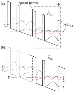
For simplicity yet still captures the essentials, in what follows we discuss a three-level QCL design with two wells per module as shown in Fig. 1 共Refs. 22and 23兲 in which
level 1
⬘
is the injector state and the radiative transition is from level 3→2. Even though typically QCL designs in-clude many more levels per period, the results obtained here hold for the triplet of levels consisting of the injector level and the two radiative levels关levels 1⬘
, 3, and 2 in Fig.1共b兲兴, regardless of a particular design, and including the mid-IR designs. Due to the various intrasubband and intersubband scattering mechanisms that contribute to quantum transport, the electron wave packets undergo dephasing, which mani-fests itself as broadening of the energy levels. The tunnel coupling between the levels of the same module is strong, therefore, dephasing has a relatively negligible effect on the intramodule intersubband transport.16 However, theinter-module transport across the injector barrier is critically af-fected by the dephasing time of the wave packets since the 1
⬘
→3 tunneling time 共half of the interwell Rabi oscillation period /⍀1⬘3兲 is now longer and of the same order. To incorporate the role of coherence in the 1⬘
→3 RT transport, we use DM rate equations corresponding to the tight-binding basis states of Fig. 1共b兲.16 The time evolution of the 3⫻3 DM for this basis set can be written as22d dtញ共1⬘,3,2兲= − i ប关Hញext,ញ共1⬘,3,2兲兴 − i ប关Hញ
⬘
,ញ共1⬘,3,2兲兴, 共1兲where Hញ
⬘
includes various radiative and nonradiative pertur-bation potentials to the conduction-band potential Hញext. The advantage of writing the DMs with the tight-binding basis of Fig. 1共b兲 is twofold. First, it allows inclusion of dephasingphenomenologically by means of decay of the coherences associated with levels 1
⬘
and 3 due to nonzero off-diagonal terms in Hញextcorresponding to those levels. Second, whereasthe eigenstates of Hˆextdepend sensitively on the externally
applied electrical bias because of coupling between spatially separated states, the chosen basis states remain more or less independent of the bias in the range of interest共i.e., close to the “design bias” corresponding to the 1
⬘
-3 alignment兲, which keeps the form factors for various intramodule scat-tering rate calculations approximately invariant of bias. In a first-order approximation, we assume RT to be independent of the electron wave vector in the plane of the QWs. The subband lifetimes are assumed to be averaged over the elec-tron distribution within a subband and are to be calculated within the Fermi’s golden rule approximation. Expanding Eq. 共1兲, we then obtaind dtញ共1⬘,3,2兲= − i
冤冢
E1⬘/ប − ⍀1⬘3 −⍀1⬘2 −⍀1⬘3 E3/ប 0 −⍀1⬘2 0 E2/ប冣
,ញ共1⬘,3,2兲冥
+冢
33 31 +22 21 −1⬘3 储13 −1⬘2 储12 −31⬘ 储13 −33 3 −33−22 st −32 储23 −21⬘ 储12 −23 储23 33 32 +33−22 st −22 21冣
. 共2兲FIG. 1. 共Color online兲 Plot of the magnitude squared envelope wave functions for a three-level QCL design with two different sets of basis functions. Plot 共a兲 is for the “extended” scheme, where energy splitting due to the injector anticrossing 2ប⍀1⬘3is visible and the wave functions are calculated for a potential profile Hˆextas
it appears in the figure. Plot共b兲 is for the “tight-binding” scheme, where the potential Hˆtbis formed by making the barriers at the
boundaries of a module sufficiently thick to confine the wave func-tions within the module.
In the equation above ញ共1⬘,3,2兲⬅
冢
1⬘1⬘ 1⬘3 1⬘2 31⬘ 33 32 21⬘ 23 22冣
,whereii共⬅ni兲 is taken as the number of electrons per
mod-ule in level i andijis the coherence共also known as
polar-ization兲 term for levels i, j. In Hញext, the diagonal terms are the
level energies given by Hˆnn=具n兩Hˆext兩n典⬇En and the level
anticrossings are represented in the off-diagonal terms as
Hˆmn=具m兩Hˆext− Hˆtb兩n典⬇−ប⍀mn. For the lifetimes, ij is the
intersubband scattering time from i→ j, 1
储ij⬅ 1 2i+ 1 2j+ 1 T2ⴱ is the dephasing rate for the coherence termijthat consists of
lifetime broadening terms as well as a phenomenological broadening term T2ⴱdue to interface roughness and impurity scattering16and
stis due to the radiative stimulated emission
above the lasing threshold共→⬁ below threshold兲. The back-scattering times23and12can also be included in Eq.共2兲 if
relevant for a particular design. Note that ⍀32= 0 for the
chosen bases since subbands 3 and 2 are the eigenstates of the tight-binding potential Hˆtbin Fig.1共b兲. By such a choice,
the role of coherence in 3→2 transport cannot be included. This does not introduce a large error in estimating the current flow since 3 and 2 are strongly coupled. In other words, if tight-binding bases were chosen for the radiative subbands 3 and 2 across the middle “radiative” barrier of the two-well module,⍀32 would be large and the Rabi oscillation period
/⍀32would be much smaller than the dephasing time储32
for the 3→2 tunneling, making 储32 inconsequential for the
3→2 transport.
As a simpler alternative to more advanced methods, Eq. 共2兲 can model some aspects of QCL transport fairly
accu-rately. Although it could be solved numerically, we seek ana-lytical expressions that could provide a greater understanding about the effect of various parameters on the transport. To-ward that goal, we assume ⍀1⬘2⬇0 akin to a unity 1
⬘
→3injection selectivity. This assumption is, in general, valid for mid-IR designs due to a large radiative level separation
E32共⬅E3− E2兲 and also becomes reasonable for the diagonal
terahertz designs.10Within this approximation, Eq.共2兲 can be
reduced to that with 2⫻2 matrices as follows:
d dtញ共1⬘,3兲= − i
冋
冉
E1⬘/ប − ⍀1⬘3 −⍀1⬘3 E3/ប冊
,ញ共1⬘,3兲册
+冢
33 31 +22 21 −1⬘3 储 −31⬘ 储 −33 31 −22 21冣
, 共3兲 where ញ共1⬘,3兲⬅共1⬘311⬘ 1⬘3 ⬘ 33 兲, 储⬅储13, 3⬅ 3132 31+32, and 33 3+ 33−22st from Eq. 共2兲 is substituted by
33
31+
22
21 in Eq. 共3兲, which holds when⍀1⬘2= 0 as a statement of current continu-ity. Additionally, we can write the following equation for22 below and above the lasing threshold:
22=
冦
33 21 32 ¯共I ⬍ Ith兲, 33−⌬nth ¯共I ⱖ Ith兲,冧
共4兲 where⌬nth=共33−22兲this the population inversion atthresh-old that is assumed to remain constant beyond threshthresh-old. Equations 共3兲 and 共4兲 can be solved analytically for steady
state共dtd→0兲. With the constraint ntot=共11+22+33兲, where ntot is the total number of electrons per module and is a
constant, the following expressions are obtained for the cur-rent I 共Ref.22兲: I⬅ 兩e兩
冉
33 31 + 22 21冊
=冦
兩e兩ntot冤
2⍀12⬘3 储 4⍀12⬘3 储冉
3132 31+32冊冉
1 + 21 232冊
+⌬12⬘3储2+ 1冥
¯共I ⬍ Ith兲, 兩e兩ntot冤
2⍀12⬘3储冉
1 − 2⌬nth ntot冋
1 −21/共231兲 1 +21/31册
冊
6⍀12⬘3 储冉
3121 31+21冊
+⌬12⬘3储2+ 1冥
¯共I ⱖ Ith兲,冧
共5兲where e is the unit charge and ប⌬1⬘3⬅E1⬘− E3 is the energy detuning between levels 1
⬘
and 3 that is a function of theexternally applied electrical bias. For the case of ultrashort lifetime of the lower radiative state 共21Ⰶ232兲, the
below-threshold term in Eq.共5兲 becomes
I =兩e兩ntot 23
冉
4⍀12⬘3 储3 4⍀12⬘3 储3+⌬1⬘3 2 储 2+ 1冊
¯ 共21Ⰶ 232, I⬍ Ith兲, 共6兲Since 21Ⰶ232 typically holds for a QCL design, the below-threshold term for the three-level model in Eq. 共5兲
does not provide any new insight from Eq.共6兲. However, the
advantage of the model lies in describing transport above threshold. It is instructive to write expressions for maximum current 共Imax兲, which flows at the 1
⬘
-3 resonance 共⌬1⬘3= 0兲for the case of a coherent RT process, i.e., a large injector coupling ⍀1⬘3.12,24 The following expressions are obtained
for Imax and the level populations when threshold could not
be attained: Imax= 兩e兩ntot 23
冉
1 + 21 232冊
, n3= n1= ntot冢
1 2 +21 32冣
, ⌬n ⬅ n3− n2 = ntot冢
1 −21 32 2 +21 32冣
¯ 共4⍀1⬘3 2 储3Ⰷ 1, Imax⬍ Ith兲. 共7兲 The results in Eq. 共7兲 are slightly different than thatob-tained using a two-level model in Ref. 12as a consequence of adding an additional level共i.e., the lower laser subband 2兲 in these calculations. However, the commonly used two-level model result Imax=兩e兩ntot/共23兲 is recovered in the limit
21Ⰶ32 as it is to be expected. Equation 共7兲 suggests that Imaxfor coherent injection is independent of⍀1⬘3, and there-fore the thickness of the injector barrier, and is limited by the upper-state lifetime 3. Typical values of ⍀1⬘3 that bring a
QCL within this limit could be determined from Fig. 2共a兲. The value of Imax, however, is different if enough population
inversion could be attained prior to the 1
⬘
-3 resonance and the device starts lasing in which case stimulated emission lowers the upper-state lifetime. In such a scenario, the maxi-mum current is limited by the lower-state lifetime21insteadand is given by
Imax=兩e兩ntot 321
冋
1 − 2⌬nth ntot + 21 31冉
1 +⌬nth ntot冊
册
, n3= n1=冉
ntot 3 + ⌬nth 3冊
¯ 共6⍀1⬘3 2 储21Ⰷ 1, Imax⬎ Ith兲. 共8兲 Equation 共8兲 implies that a QCL with a large injectorcou-pling ⍀1⬘3 and a short lower-state lifetime21 can possibly obtain a large dynamic range in current due to a large Imax
关see Figs.3共c兲and3共d兲兴. However, it may be noted that for
coherent injection, the gain linewidth of the QCL becomes additionally broadened as the injector coupling ⍀1⬘3 is
in-creased. Consequently, a larger ⌬nth is required to attain a certain value of peak gain, which mitigates the increase in the value of Imax. This will become more clear in Sec. III
from the gain spectrum calculations for some specific cases. Approaching threshold, the value of current that must flow through the QCL structure to establish a population in-version of⌬nthis calculated to be Ith= 兩e兩⌬nth 3
共
1 − 21 32兲
. 共9兲While the above expression for Ithcan also be derived from
a simple rate equation analysis, the minimum value of ⍀1⬘3
needed for a current Ith to flow through the structure is
de-rived from the present three-level DM model as
0 0.1 0.2 0.3 0.4 0.5 10−1 100 101 102 ∆ nmax/n tot (∆ 1’3 /h) 2τ || τ 3 ξ=0.5 ξ=0.3 ξ=0.1ξ=0 ξ ≡ τ21/τ32 0 10 20 30 40 50 60 70 80 90 100 g (cm−1) 0 0.5 1 1.5 2 2.5 3 3.5 4 4.5 5 10−1 100 101 102 (∆1’3 /h) 2τ || τ3 ∆1’3(meV) 1/τ||= 1/(2τ3)+1/T * 2 T* 2= 0.75 ps τ3= 0.3 ps τ3= 0.75 ps τ3= 1.5 ps τ3= 3.0 ps
FIG. 2.共Color online兲 共a兲 A plot of the factor 4⍀12⬘3储3to determine the regime of RT transport through the injector barrier共Ⰷ1 coherent
andⰆ1 incoherent兲. A phenomenological value of T2ⴱ= 0.75 ps is assumed.共b兲 A related plot to determine the maximum value of population inversion 共n3− n2兲 that can be attained for a given ⍀1⬘3, calculated using Eq. 共10兲. The top axis converts ⌬n on the bottom axis to
corresponding values of peak gain for the following typical parameters: ntot/volume=5⫻1015 cm−3, f32= 0.5,⌬=1.0 THz, and using the
expression g⬇70关⌬n/共10 15cm−3兲兴f
32
关⌬/共1 THz兲兴 关cm−1兴 for GaAs material 共Ref. 6兲 that assumes a Lorentzian gain linewidth of ⌬ 共note that f32is the
4⍀12⬘3 储3⬎ 2⌬nth ntot− 2⌬nth−共ntot+⌬nth兲21 32 . 共10兲
This result is obtained from Eq.共5兲 as a necessary condition
for the two expressions to have the same value for some particular bias ⌬1⬘3. An estimate of the minimum value of ⍀1⬘3required to meet this condition can be obtained from the
plots in Fig. 2共b兲. Figure 2共b兲 can also be interpreted in a different way since it determines the maximum value of population inversion that can be attained for a given ⍀1⬘3.
For example, in the limit 21→0, a maximum of
⌬n=ntot/2 can be obtained if 4⍀1⬘3
2
储3Ⰷ1.
A. Current-voltage characteristics for typical parameters
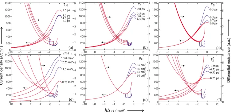
To gauge the effect of various parameters on QCL’s per-formance, Fig. 3 shows calculation of the current-voltage 共I-V兲 and differential-resistance-voltage 共R-V, R=dV
dI兲
char-acteristics for a range of parameters using the analytical ex-pressions in Eq.共5兲. The I-V’s show a discontinuity in slope
at the occurrence of the lasing threshold, as was first dis-cussed in detail in Ref. 12. However, any discussion about the differential resistance in the present context is left until later. For the I-V’s the main features to be noted are the values of the threshold current density Jthand the maximum
current density Jmax. In general for any design, the goal is to obtain a larger dynamic range for lasing Jmax/Jthwhile also
keeping the value of Jthlow. A larger dynamic range leads to
greater amount of the optical power output and also a higher operating temperature Tmax. As it is to be expected, the plots show that the laser performance improves by making31and
32 larger, and21 smaller.
We now compare the three-level model I-V’s in Fig. 3to those experimentally measured for two different RPTQCL designs. Figure 4 shows typical results from a four-level10,26,27 and a five-level6,8 RPTQCL, respectively. The structures in Figs. 4共a兲 and 4共b兲 can be qualitatively analyzed with the three-level model of this section by using the following expression for the effective lifetime of the lower laser level 2, which is depopulated through RT into 2a and subsequently via electron-longitudinal-optical 共e-LO兲 phonon scattering into the injector level共s兲 共i.e., the
resonant-phonon scheme兲. The following expression can be derived
using a two-level density matrix for levels 2 and 2a exclu-sively and assuming 2→2a tunneling to be the only mecha-nism for carrier injection into level 2a,22
2,eff=2a
冉
2⍀2,2a2 储2a+⌬2,2a2 储2+ 1 2⍀2,2a2 储2a
冊
. 共11兲 The effective lower-level lifetime 2,eff, which is also
−100 −8 −6 −4 −2 0 2 200 400 600 800 1000 1200 1400 0 1 2 3 4 5 6 −100 −8 −6 −4 −2 0 2 200 400 600 800 1000 1200 1400 0 1 2 3 4 5 6 −100 −8 −6 −4 −2 0 2 200 400 600 800 1000 1200 1400 0 1 2 3 4 5 6 −100 −8 −6 −4 −2 0 2 200 400 600 800 1000 1200 1400 0 1 2 3 4 5 6 −100 −8 −6 −4 −2 0 2 200 400 600 800 1000 1200 1400 0 1 2 3 4 5 6 −100 −8 −6 −4 −2 0 2 200 400 600 800 1000 1200 1400 0 1 2 3 4 5 6
FIG. 3. 共Color online兲 Calculations of the current density 共I/area兲 as a function of the energy detuning ប⌬1⬘3关which is proportional to
the external bias voltage V, as in Eq.共12兲兴 and its inverse slope兩e兩បd⌬1⬘3
dI 关which is proportional to the differential resistance R, as in Eq. 共13兲兴.
The calculations are done for a range of parameters using Eq.共5兲 for the three-level model. Following default values are chosen corre-sponding to the typical values for RPTQCL designs: 2ប⍀1⬘3= 1.5 meV, T2ⴱ= 0.75 ps, gth= 40/cm 共Ref.25兲,21= 0.5 ps,32= 3.0 ps, and
31= 5.0 ps. A doping density ntot/volume=5⫻1015 cm−3is used. The radiative transition is assumed to have a Lorentzian linewidth of
⌬=1.5 THz 共the broad linewidth is based on the findings of Sec.III兲 and an oscillator strength of f32= 0.6 to determine the population
inversion⌬nthrequired to attain a particular value of threshold gain gth. The thin共red兲 portion of the curves corresponds to I⬍Ithwhile the thick共blue兲 region is for I⬎Ithwhere the occurrence of threshold is marked by a discontinuity inR. Each of the subplots show the variation
in the I-V’s and theR-V’s when only a single parameter is changed, the others being kept at the values mentioned above. Note that additional linewidth broadening due to coherent effects共discussed in Sec.III兲 is not considered for calculations of the curves above threshold.
equivalent to the tunneling time through the collector barrier, is plotted for three different values of the collector anticrossing 2ប⍀2,2a in Fig. 5. The best performing
RPTQCLs have large collector anticrossings in the range of 2ប⍀2,2a⬃4–5 meV in which case 2,eff varies little in the operating bias range close to the 2-2a resonance 共ប⌬2,2a= 0兲. For example, 2ប⍀2,2a⬃4.7 meV for the
four-level QCL in Ref. 10 and the energy detuning ប⌬2,2a
ap-proximately varies from −2 to 2.5 meV in operating bias range of the design. As seen from Fig. 5共a兲, 2,eff changes
little within such a range of detuning.
We can similarly take the combined population
ntot= n1⬘+ n2+ n3 to be approximately bias independent. The
population of level 2a is likely to be negligible due to its very short lifetime 2a⬃0.2 ps and that of level 1a in Fig.
4共b兲 is likely to vary negligibly with bias in the operating bias range of interest due to the typically large values of the intrainjector anticrossing 2ប⍀1a,1⬃4–5 meV in the
five-level design Fig. 4共b兲. Given the bias independence of
ntot= n1⬘+ n2+ n3 and the lower-level lifetime 2,eff for the resonant-phonon designs in Fig.4, we can now qualitatively compare the three-level model I-V’s in Fig.3 to the experi-mental cw I-V’s in Fig.4. For the latter, it can be noticed that
Jmax, which is characterized by the occurrence of a
negative-differential-resistance region in the I-V, changes little up un-til the maximum operating temperature of the laser Tmax,cw.
However, beyond Tmax,cw, the value of Jmax increases with temperature. This characteristic is best described by the cal-culated I-V’s in Fig. 3共a兲 since the above-threshold current expression in Eq. 共5兲 is independent of the upper-state to
lower-state lifetime32to a first order. Hence, it is likely that
one of the dominant temperature degradation mechanism for RPTQCLs is a reduction in the upper-state共u兲 to lower-state 共l兲 lifetime, which is mostly attributed to the thermally acti-vated LO phonon scattering from the upper state.5,6The
re-cently developed terahertz QCL design with a very diagonal radiative transition is based on this observation to effectively increase the u→l lifetime at high temperatures.10 Addition-ally, it seems less likely that an increase in the effective lifetime of the lower state 关potentially due to 1→2 thermal backfilling or increased dephasing for the 2→2a RT that affects 2,eff as in Fig. 5共b兲兴 or a broadening of the gain
linewidth28 are more dominant temperature degradation
0 2 4 6 8 10 12 0 100 200 300 400 500 600 700 800 Bias (V) Current Density (A/cm 2) 10K 84K 98K 111K 136K Lasing threshold 0 2 4 6 8 10 12 14 16 18 0 100 200 300 400 500 600 700 800 900 Bias (V) Current Densit y( A/cm 2) 10K 52K 65K 74K 81K Lasing threshold 1 1a 2a 2 3 1’ 1a’ Collector barrier Injector barrier Injector region Active region ×N
5−level resonant−phonon design
(b) 1’ 3 2a 1 2 Injector region Active region ×N Collector barrier Injector barrier
4−level resonant−phonon design
(a)
FIG. 4. 共Color online兲 Typical experimental I-V’s versus tem-perature for 共a兲 a four-level and 共b兲 a five-level resonant-phonon terahertz QCL, respectively. The corresponding band diagrams show tight-binding wave functions at design bias calculated by splitting the QCL module into multiple submodules across the rel-evant barriers. The radiative transition is from 3→2, and the de-population of the lower level is via 2→2a RT and 2a→1/1a electron-longitudinal-optical phonon scattering where E21⬇បLO.
The I-V’s are measured in cw operation for metal-metal ridge la-sers. The plot in共a兲 is from a 3.9 THz QCL labeled OWI222G 共Ref. 10兲 of dimensions 60 m⫻310 m 共Tmax,cw⬃76 K兲 and that in 共b兲 is from a 2.7 THz QCL labeled FL178C-M10 共Ref.6兲 of dimen-sions 35 m⫻670 m 共Tmax,cw⬃108 K兲. The onset of lasing re-sults in a change in the slope of the I-V, which is indicated by arrows for the curves recorded below the Tmax,cw.
−4 −2 0 2 4 0 0.2 0.4 0.6 0.8 1 1.2 1.4 1.6 1.8 2 τ2,eff (ps) h∆2,2a(meV) 2hΩ2,2a= 5.0 meV 2hΩ2,2a= 3.0 meV 2hΩ2,2a= 2.0 meV τ2a= 0.2 ps T*2= 0.75 ps 0 0.2 0.4 0.6 0.8 1 1.2 1.4 0 0.2 0.4 0.6 0.8 1 1.2 1.4 1.6 1.8 2 τ 2,eff (ps) T*2(ps) 2hΩ2,2a= 5.0 meV 2hΩ2,2a= 3.0 meV 2hΩ2,2a= 2.0 meV τ2a= 0.2 ps h∆2,2a= 0 meV
FIG. 5. 共Color online兲 Plots of the effective lower-level lifetime 2,eff 共also equivalent to the tunneling time through the collector
barrier兲 for the resonant-phonon designs of the type shown in Fig.4 calculated using Eq. 共11兲. Plot 共a兲 shows 2,eff versus the energy
detuning ប⌬2,2abetween the levels 2 and 2a and 共b兲 shows2,eff versus the phenomenological dephasing time T2ⴱcalculated at the 2-2a resonance bias共ប⌬2,2a= 0兲.2a⬃0.2 ps is assumed owing to the typical value obtained in GaAs/Al0.15Ga0.85As quantum wells
mechanisms than that mentioned above; otherwise, the ob-served experimental behavior would have corresponded more closely with Fig.3共e兲or Fig.3共c兲, respectively. That is, the peak current density Jmaxwould decrease at elevated
tem-peratures.
The two-well design of Fig. 1, which features an
intrawell-phonon 共IP兲 depopulation scheme as opposed to
the RP depopulation scheme of Fig.4, has also been experi-mentally realized recently.23 The design-bias band diagram
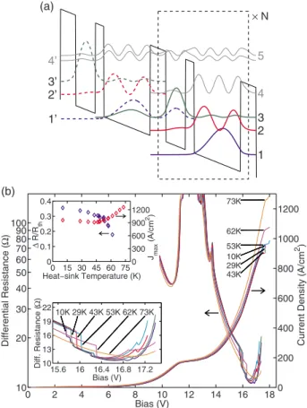
of the realized structure is shown in Fig. 6共a兲 including higher energy parasitic levels that are believed to contribute to electron transport at elevated temperatures. The experi-mental I-V’s and R-V’s from a representative ridge laser in cw operation are shown in Fig.6共b兲. The temperature varia-tion in the I-V’s shows that Jmaxfor this IP QCL decreases slightly with temperature up to T⬃45 K and subsequently increases steeply with temperature until and beyond the
Tmax,cw⬃63 K. This unique dependence of Jmaxwith T, also
shown explicitly in the inset of Fig. 6共b兲, is different from
that of the RP QCLs in Fig.4and is attributed to the onset of a temperature degradation mechanism that is in addition to the reduction in32due to thermally activated e-LO phonon
scattering from 3→2. It is postulated that the lifetime of the upper state 3 decreases additionally due to absorption of nonequilibrium 共hot兲 LO phonons via 3
⬘
→共4⬘
, 5兲 scattering.23Any such scattered electrons quickly relax backeventually into the injector level of a neighboring module due to the short lifetime of the parasitic levels 4 and 5 共4⬘⬃5⬃0.3 ps兲. Such a leakage mechanism can be
con-sidered approximately as an effective reduction in31 in
or-der to apply the results of the three-level model to explain the behavior in Fig. 6共b兲, which then becomes consistent with calculated I-V behavior in Fig.3共b兲. Note that the upper laser state in the RP designs is spatially isolated from the wide injector well共s兲 and hence from the higher energy para-sitic levels.6 Hence, the aforementioned hot-phonon
medi-ated leakage mechanism is weaker for the RPTQCLs as com-pared to the IP QCL structure of Fig.6共a兲.
B. Discontinuity in differential resistance at threshold
The onset of lasing in a QCL is characterized by a slope discontinuity in its I-V characteristics.12This is a
manifesta-tion of the increased rate of carrier flow due to the stimulated emission process from the upper to the lower state, such that the population inversion is kept constant beyond threshold. The relative change in the differential resistance R=dV/dI of the device at threshold is a useful parameter since it is easily and accurately measurable and is shown below to be directly proportional to the value of⌬nth. We can relate the
externally applied bias voltage across all the periods of the QCL to the energy detuningប⌬1⬘3as
V =ប⌬1⬘3Np fV兩e兩
, 共12兲
where Npis the number of repeated periods in the QCL
struc-ture and fV is the fraction of per module voltage bias V/Np
that appears as the energy difference between levels 1
⬘
and 3.fV is typically a slowly varying nonlinear function of the
applied voltage V and is a characteristic of a particular de-sign as shown in Fig.7. For the main result presented in this section, the particular form of fVis inconsequential and it is
assumed to be a constant in the bias range right below and above the threshold. Using Eq.共12兲 the differential resistance R becomes R =dV dI ⬇ បNp fV兩e兩 dE1⬘3 dI . 共13兲
In Eq.共13兲, we have dropped the term corresponding to dfV
dI since fVis approximately a constant as can be seen from
Fig.7. The calculations in Fig.7 are done without account-ing for band bendaccount-ing due to dopant-carrier segregation, which is typically insignificant due to the low doping in such QCL structures.19The value of dfV
dI is likely to be negligible
in comparison to the leading term of Eq.共13兲 even if band
bending were found to be significant for a particular design. We can now derive analytical expressions for the ratio as
1 2 3 4 5 1’ 2’ 3’ 4’ × N (a) 0 2 4 6 8 10 12 14 16 180 200 400 600 800 1000 1200 Bias (V) Current Density (A/cm 2) 10K 29K 43K 53K 62K 73K (b) 10 20 30 40 50 60 70 80 90 100 Differential Resistance (Ω ) 15.6 16 16.4 16.8 17.2 10 13 16 19 22 Bias (V) Diff. Resistance (Ω ) 10K 29K 43K 53K 62K 73K 0 15 30 45 60 75 0 0.1 0.2 0.3 0.4 Heat−sink Temperature (K) ∆ R/R th 0 300 600 900 1200 Jmax (A/cm 2)
FIG. 6. 共Color online兲 共a兲 Conduction-band diagram of a re-cently demonstrated two-well terahertz QCL design, labeled TW246 共Ref. 23兲. Only three levels 共1, 2, and 3兲 participate in transport at low temperatures; however, at higher temperatures ad-ditional parasitic levels共4 and 5兲 are also likely to contribute to the current flow.共b兲 Experimental cw I-V’s and R-V’s at different heat-sink temperatures from a 20 m⫻1.56 mm metal-metal ridge la-ser with a Tmax,cw⬃63 K. The lasing threshold is marked by a
discontinuity in the R curves that is shown more clearly in an expanded view in the lower inset. The upper inset shows the varia-tion in fracvaria-tional discontinuity inR at threshold⌬Rth
Rth共⬅
Rth−−Rth+
Rth− 兲 and of Jmaxwith temperature.
well as the fractional change in differential resistance just below共Rth−兲 and above 共Rth+兲 threshold using Eq. 共5兲 to
cal-culate d⌬dI1⬘3. The individual expressions forRth− andRth+ are complicated; however, the ratio Rth
+
Rth− and hence the fractional change in R at threshold ⌬Rth Rth is expressed in a surprisingly concise form as22 Rth+ Rth − =
冤
1 − 2⌬nth ntot冢
1 − 21 231 1 +21 31冣冥
, 共14兲 ⌬Rth Rth ⬅ Rth−−Rth+ Rth− =2⌬nth ntot冢
1 − 21 231 1 +21 31冣
. 共15兲Note that Eq.共15兲 is derived for the case of unity injection
efficiency, i.e., ⍀1⬘2⬇0 in the 3⫻3 DM Eq. 共2兲. Hence,
within the approximation that the current flow due to the 1
⬘
→2 channel is negligible in comparison to the 1⬘
→3 channel at threshold, the expression derived for ⌬RRthth holds true irrespective of the nature of the RT transport 共coherent or incoherent兲 across the injector barrier. At low tempera-tures,21Ⰶ31 and hence ⌬RthRth ⬇
2⌬nth
ntot gives an absolute
mea-surement of the population inversion in the laser as a fraction of the combined populations of the injector level 1
⬘
and the laser levels 3 and 2共ntot⬅n1⬘+ n2+ n3兲.The slope efficiency of a QCL’s optical power output is written as dPout dI = Npប0 兩e兩 ␣m 共␣w+␣m兲 , 共16兲
where0is the lasing frequency,␣mis the radiative共mirror兲 loss in the cavity,␣wis the material共waveguide兲 loss, and
is the internal quantum efficiency of the QCL structure.
⬍1 due to the fact that n3and hence the nonradiative
com-ponent of the current I共=兩e兩n3/3兲 continues to increase with
I above threshold共even as ⌬n=n3− n2remains fixed at⌬nth兲,
which causes the current above threshold 共I−Ith兲 to be not
entirely due to radiative transitions. An expression for is derived as = 1 −21 32 1 +21 31 = 1 −
冏
dn3 dI冏
I=I th +冏
dn3 dI冏
I=I th − , 共17兲 where冏
dn3 dI冏
I=I th += 1 兩e兩 2131 共21+31兲 ,冏
dn3 dI冏
I=I th − = 1 兩e兩3. 共18兲Equation共17兲 forcan also be derived from a rate equation model since n3can be expressed in terms of I regardless of
the nature of 1
⬘
→3 RT transport. In literature,12,29 ⌬RthRth has similarly been derived from a rate equations approach, argu-ing that n3⬀⌬1⬘3, and hence the applied voltage V, in which
case ⌬Rth
Rth becomes same as共for unity injection efficiency兲, and hence an indicator of the ratio of laser level lifetimes
21/32. However, the expression for ⌬Rth
Rth in Eq. 共15兲 is starkly different from that of in Eq.共17兲. While→1 for
21→0 but ⌬Rth
Rth →
2⌬nth
ntot . Also, strongly depends on the upper-state to lower-state lifetime 32, whereas ⌬Rth
Rth is inde-pendent of32. Hence, the result derived with the three-level
DM model has important implications in the way the slope discontinuity is interpreted for the I-V of a QCL at threshold. In essence, ⌬Rth
Rth is an indicator of the population inversion at threshold and not the ratio of level lifetimes, which are two different aspects of laser operation.
By means of Fig. 8, we now show that the assumption
n3⬀⌬1⬘3, which is the basis of the previously held belief of ⌬Rth
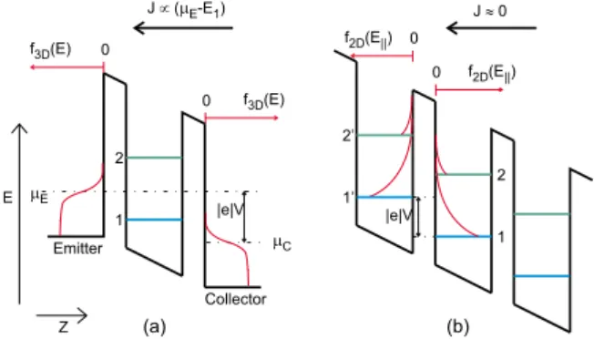
Rth being equivalent to, is incorrect. For the conventional resonant-tunneling diode structures, carriers tunnel from the three-dimensional states in the emitter into the quasi-two-dimensional states in the well. Considering only first-order tunneling processes 共i.e., conservation of in-plane momen-tum in tunneling through the barriers兲, the current flow is proportional to the Fermi energyEin the emitter and hence
the applied voltage V关as shown in Fig.8共a兲, see Ref.31, for example兴. In such a case, the population n1of the subband 1 in Fig.8共a兲will indeed be proportional to V. However, for a semiconductor superlattice structure of which QCLs are spe-cific examples, the current flow will be negligible if the
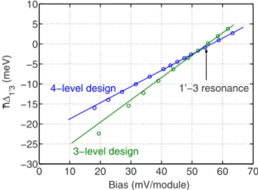
sub-0 10 20 30 40 50 60 70 −30 −25 −20 −15 −10 −5 0 5 10 Bias (mV/module) h∆ 1’3 (meV) 1’−3 resonance 3−level design 4−level design
FIG. 7. 共Color online兲 Detuning energy ប⌬1⬘3as a function of the voltage per QCL module 关=V/Np in Eq. 共12兲兴 for the
tight-binding wave functions of the four-level resonant-phonon design of Fig. 4共a兲 and the three-level intrawell-phonon design of Fig.6共a兲, respectively. Small circles represent calculated values, which are overlaid with straight line fits to the data points close to the 1⬘-3 resonance. The fits indicate that ប⌬1⬘3 is linearly related to V/Np
close to the 1⬘-3 resonance 关i.e., fV in Eq. 共12兲 is a constant兴. Typically, lasing threshold occurs after the 1⬘-2 resonance 共⬃30 mV/module兲 beyond which the current continues to increase up to the 1⬘-3 resonance when Jmaxoccurs.
bands are significantly off-resonance in the neighboring quantum wells even if the carrier distributions overlap in energy. This is because total energy cannot be conserved in such a tunneling process since the in-plane momentum con-servation needs to be satisfied. The applied bias field is in the
z direction and hence affects the bottom energy of the
sub-bands and their z-wave functions, however, the quasi-Fermi levels within the respective subbands represent the in-plane carrier distribution and are not directly affected by the ap-plied voltage V. As a result, the subband populations cannot be assumed to be directly proportional to V. Instead, the subband populations and their thermal distributions 共and hence the respective quasi-Fermi levels兲 are determined by the various intersubband and intrasubband scattering pro-cesses and also by the resonant-tunneling current flow in-duced by the coupling of the subband wave functions across the barriers as determined by the anticrossing energies 2ប⍀ij
and detuning energies ប⌬ij. Note that higher order
correc-tions to the resonant-tunneling current flow that relax the requirement of plane momentum conservation are not in-cluded in this simplified picture.18,32
Figure 9shows typical variation in ⌬Rth
Rth with31 accord-ing to Eq. 共15兲, which shows that ⌬Rth
Rth decreases rapidly as
31becomes smaller and approaches21. The trend in Fig.9
could be compared to the experimental variation in⌬Rth
Rth with temperature for the two-well QCL shown in the upper inset of Fig.6共b兲, which indicates a steady degradation of its ef-fective 31 with temperature due to a predicted hot-phonon effect.23 Also note that J
max and
⌬Rth
Rth in Fig. 6共b兲 have a
correlated behavior where Jmax↑ as ⌬Rth
Rth↓. This validates the expression in Eq. 共5兲 for operation above threshold, which
suggests Jmax⬀共1−⌬Rth
Rth兲, where Jmaxis the current flowing at 1
⬘
-3 resonance共⌬1⬘3= 0兲 and Eq. 共15兲 is used forsubstitu-tion. For this IP QCL also, gain bandwidth broadening with temperature is less likely to be the dominant temperature degradation mechanism. Otherwise, the value of ⌬Rth
Rth should increase according to Eq. 共15兲 with the requirement of a
larger population inversion to reach threshold.
III. OPTICAL GAIN SPECTRUM OF RESONANT-PHONON TERAHERTZ QCLs
Terahertz QCL designs with RP depopulation typically have broad gain linewidths. The spontaneous emission spec-tra from one of the earliest such designs had a ⬃2 THz full-width half-maximum共FWHM兲 linewidth for a ⬃4 THz QCL active region.19 Experimental spontaneous emission
data for some of the more recent high performance designs10,33 is not available because of the difficulty in
ob-serving subthreshold optical signal in metal-metal waveguides,34 both because of the low loss in these
waveguides that causes lasing soon after the upper level is populated with electrons and also due to the poor out-coupling efficiency of such cavities.35 However,
simulta-neous lasing of modes separated by frequencies greater than 0.5 THz共Refs.20and36兲 suggests that large gain exists over
a broad bandwidth that is a significant fraction of the center frequency in a homogeneously grown RPTQCL design 共in contrast to heterogeneous cascade designs that have been used to realize broad gain bandwidths at mid-infrared frequencies37兲.
In this section, we use density matrices to numerically estimate the optical gain spectrum in a RPTQCL design and find reasons for broadening of the gain spectrum. Similar to the I-V calculations in Sec.II, the simplified DM calculations are shown to be an effective method to understand the role of various design parameters toward the optical response of a terahertz QCL gain medium, as opposed to the nonequilib-rium Green’s function technique that incorporates a full
FIG. 8. 共Color online兲 Illustrative band diagrams for 共a兲 double-barrier resonant-tunneling diode structure共Ref.30兲 that consists of a single quantum well sandwiched between degenerately doped emitter and collector regions, and 共b兲 a superlattice structure 共Ref.1兲 that consists of multiple repeated quantum wells of which only three wells are shown. In 共a兲, the shown Fermi distributions 共indicated by thin red lines兲 for the carrier populations apply to a quasicontinuous carrier distribution in three dimensions, whereas in 共b兲, the shown carrier distribution applies only to the two-dimensional momentum space in the x-y plane 共since the carriers are confined in the z direction兲 and is typically Maxwell-Boltzmann type共i.e., the Fermi energynlies much below the energy of the bottom of the subband En indicated by thick horizontal lines兲. In
共a兲, V is the voltage applied between the emitter and the collector that appears as the difference between the respective Fermi energies and in 共b兲 V represents the voltage per repeated module of the superlattice that appears as the difference in the energy of the bot-tom of the subbands.
10 9 8 7 6 5 4 3 2 1 0 0 0.1 0.2 0.3 0.4 0.5 0.6 τ31(ps) τ21 = 0.2 ps τ21 = 0.5 ps τ 21= 1.0 ps ∆ Rth /R th
FIG. 9. 共Color online兲 Variation in the fractional change in dif-ferential resistance at threshold ⌬Rth
Rth with31calculated using the expression in Eq.共15兲 with same typical values of different param-eters as in Fig.3.
quantum theory of gain.38,39 Similar calculations have been
used recently to determine the optimal injector coupling in mid-infrared QCLs共Ref.40兲 and also to describe the
electri-cal transport characteristics of RT extraction based terahertz QCL structure.14 We consider the simplest RP design with
four levels per QCL period as shown in Fig.10. To compute the gain 共or loss兲 spectrum, the linear response to a
sinusoidal electric field perturbation of the form
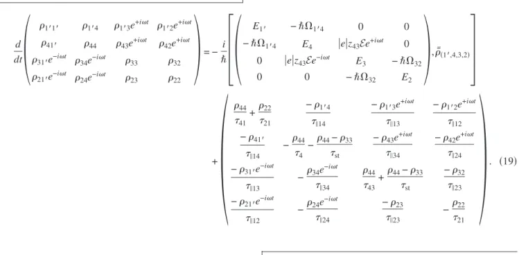
E = zˆE共e+it+ e−it兲 is calculated by incorporating the electric dipole interaction term for coherent coupling of the radiative levels. Only the electric field component in the growth direc-tion zˆ is considered due to the intersubband polarizadirec-tion se-lection rule. The time evolution of the DM for the four-level design is then written as22
d dt
冢
1⬘1⬘ 1⬘4 1⬘3e+it 1⬘2e+it 41⬘ 44 43e+it 42e+it 31⬘e−it 34e−it 33 32 21⬘e−it 24e−it 23 22冣
= − i ប冤冢
E1⬘ −ប⍀1⬘4 0 0 −ប⍀1⬘4 E4 兩e兩z43Ee+it 0 0 兩e兩z43Ee−it E3 −ប⍀32 0 0 −ប⍀32 E2冣
,ញ共1⬘,4,3,2兲冥
+冢
44 41 +22 21 −1⬘4 储14 −1⬘3e+it 储13 −1⬘2e+it 储12 −41⬘ 储14 −44 4 −44−33 st −43e+it 储34 −42e+it 储24 −31⬘e−it 储13 −34e −it 储34 44 43 +44−33 st −32 储23 −21⬘e−it 储12 −24e −it 储24 −23 储23 −22 21冣
. 共19兲Equation 共19兲 is written similarly as Eq. 共2兲 with
addi-tional modifications due to the sinusoidal electric field per-turbation. We consider linear response within the rotating-wave approximation 共i.e., 兩−43兩Ⰶ兲 in which case the
affected coherences can be explicitly written to have a sinu-soidal time variation as shown with the slowly varying am-plitudesmn. The radiative levels 3 and 4 are now coherently
coupled through the off-diagonal electric dipole interaction term 兩e兩r·E that has an amplitude 兩e兩z43E, where z43=具4兩zˆ兩3典 is the dipole-matrix element for the said
tight-binding levels. Since共1
⬘
, 4兲 and 共3,2兲 are coherently coupled due to nonzero⍀1⬘4 and⍀32 terms, respectively, thecoher-ences corresponding to 共1
⬘
, 3兲, 共1⬘
, 2兲, and 共4,2兲 acquire a time-harmonic character due to the time-harmonic共4,3兲 co-herent coupling. The sinusoidal component of the coherences is written explicitly in the ansatzd 共1⬘,4,3,2兲 in which casemn
dt = 0 in the steady state for the slowly varying amplitudes
mn. Note that 共1⬘,4,3,2兲 on the right side of Eq. 共19兲 is the
same as the left-side matrix appearing with the time deriva-tive.
We made some simplifying approximations in writing Eq. 共19兲. Similar to before, for simplicity of calculations, we
assume a unity injection efficiency 共⍀1⬘3⬇0兲, also a unity
collection efficiency 共⍀42⬇0兲, and neglect the
backscatter-ing terms12and34. For nonzero⍀1⬘3and/or⍀42, Eq.共19兲
will become more complicated since some of the nonhar-monic terms in the ញ共1⬘,4,3,2兲 matrix will additionally acquire harmonic character and similarly some of the
time-harmonic coherences will additionally acquire a constant value in the steady state, thereby effectively increasing the number of independent variables to be solved for the system 共currently 16 for the written equation兲. Also, a parameter41
1’ 4 2 1 3 Injector region Active region ×N Collector barrier Injector barrier
4−level resonant−phonon THz QCL design
FIG. 10. 共Color online兲 The four-level resonant-phonon tera-hertz QCL structure reproduced from Fig.4共a兲with a different level numbering scheme for simplicity of presentation in the following discussions. The radiative transition is from 4→3, and depopula-tion of the lower level is via 3→2 RT and 2→1 e-LO phonon scattering where E21⬇បLO.
is included to incorporate the effect of any indirect parasitic scattering channels from 4 to 1 since direct 4→1 transport is otherwise only allowed via intersubmodule tunneling across the collector barrier for the chosen set of tight-binding basis functions. We can now solve this equation, which, in addi-tion to yielding values of current and level populaaddi-tions, also yields the electrical polarization zˆP共t兲 induced due to the external optical field E as
P ⬅⑀0共兲Ee+it+ c.c. =−兩e兩具zˆ典 Vac =−兩e兩z43 Vac 兵关43共兲 +34共−兲兴e+it+ c.c.其, 共20兲
where Vac is the volume of the active region. The induced
electrical susceptibility共兲 becomes
共兲 ⬅
⬘
共兲 + i⬙
共兲 =−兩e兩z43Vac⑀0E关43共兲 +34共−兲兴,
共21兲 which is independent of the amplitude E for small values. The optical gain coefficient g共兲 共per meter兲 is related to the imaginary part of the susceptibility
⬙
共兲 asg共兲兩共⬘,⬙兲Ⰶn r 2=
⬙
共兲 nr c, 共22兲where nr is the refractive index of the medium. In the
fol-lowing, we show results of the computed gain spectrum as a function of several different parameters of interest.
A. Optical gain spectrum as a function of injector anticrossing
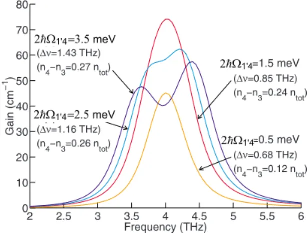
Figure 11 shows the numerically computed gain spectra for the four-level RPTQCL design as modeled by Eq. 共19兲
for different values of injector anticrossing 2ប⍀1⬘4. For the
4→3 radiative transition, the FWHM frequency linewidth due to scattering is given by ⌬scatt⬇
1 关213,eff+ 1 24+ 1 T2ⴱ兴, which yields a value of 0.67 THz共h⌬scatt⬃2.75 meV兲 for the chosen parameters. The value of T2ⴱ= 0.75 ps was as-sumed for the above value of the linewidth to approximately agree with those observed typically for bound-to-continuum THz QCLs共Refs. 41–43兲 whose linewidths are more likely
to be scattering limited. As 2ប⍀1⬘4 becomes as large as
h⌬scatt, injector transport becomes more coherent and the
gain spectrum becomes additionally broadened due to anti-crossing splitting of the linewidth as can be seen from Fig.
11. Also note that the population inversion ⌬n approaches the maximum value given by Eq. 共7兲 for coherent injection,
which, for the present case yields ⌬nmax⬃共 1−3,eff/43
2+3,eff/43兲
ntot⬇0.28 ntot. The area under the gain curve is proportional
to the population inversion ⌬n43, therefore, any additional
broadening decreases the peak gain. This suggests that a value of 2ប⍀1⬘4 much larger than h⌬scattmight in fact di-minish the performance of a design. However, as will be shown in the next section, RPTQCL designs anyway have broad linewidths due to a coherent RT assisted depopulation process in which case having 2ប⍀1⬘4⬎h⌬scattis less likely
to cause additional broadening of the gain linewidth. Conse-quently, the injector anticrossing value for the RPTQCL de-signs is chosen based on other design parameters such as the 1
⬘
→3 parasitic current leakage10 rather than the concernsabout gain broadening.
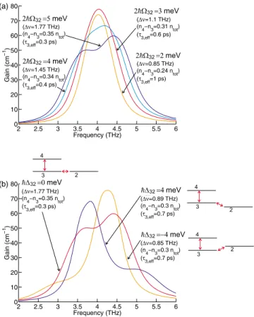
B. Optical gain spectrum as a function of collector anticrossing
Figures 12共a兲and12共b兲 show the computed gain spectra for different values of collector anticrossings 2ប⍀32and
en-ergy detuningប⌬32, respectively. The best RPTQCL designs typically have collector anticrossing values in the range of 4–5 meV. This is to maintain a short effective lower-state lifetime so as to maximize Jmax/Jthsince Jmax⬀lower−1 for
co-herent injection 关Eq. 共8兲兴, although at the cost of a broader
linewidth. For example, the 2ប⍀32= 5 meV spectrum in Fig.
12共a兲 has a FWHM linewidth of 1.8 THz, a value almost twice as large as the scattering linewidth ⌬scatt⬃1 THz
共calculated using 3,eff⬃0.3 ps兲. This shows that the
anti-crossing splitting of the gain spectrum due to the coherent RT assisted depopulation process is the main cause of the broad linewidths associated with RPTQCLs.19,20,36 As seen
from Fig.12共b兲, note that linewidth broadening happens only close to the 3-2 resonance at ប⌬32⬇0. For 兩ប⌬32兩⬎0 and 兩ប⌬32兩Ⰶ”E43, the width of the spectrum remains narrow since
the 4→2 radiative transition 共which is indirect, and due to 4↔3 and 3↔2 coherent coupling兲 is considerably detuned from the stronger 4→3 radiative transition 共which is direct and due to 4↔3 coherent coupling兲, and hence contributes negligibly to the gain. For a coherent 3→2 RT process 共i.e., large ⍀32兲, the peak gain occurs at a frequency
2 2.5 3 3.5 4 4.5 5 5.5 6 0 10 20 30 40 50 60 70 80 Frequency (THz) Gain (cm − 1 ) ∆1’4=0.5 meV (∆ν=0.68 THz) (n 4−n3=0.12 ntot) ∆1’4=1.5 meV (∆ν=0.85 THz) (n 4−n3=0.24 ntot) ∆1’4=2.5 meV (∆ν=1.16 THz) (n4−n3=0.26 ntot) ∆1’4=3.5 meV (∆ν=1.43 THz) (n4−n3=0.27 ntot)
FIG. 11.共Color online兲 Computed gain spectra for the four-level structure of Fig. 10 for different injector anticrossings 2ប⍀1⬘4, evaluated at 1⬘-4 resonance共⌬1⬘4= 0兲. Levels 3 and 2 are also taken
to be at resonance共⌬32= 0兲 and a small value of 2ប⍀32= 2 meV is chosen to limit additional broadening due to a coherent 3→2 RT process 关as shown in Fig. 12共a兲兴. All other parameters have same equivalent values as in Fig.3, except21= 0.2 ps that results in an
effective lower-state lifetime 3,eff共⬅
n3
n221兲⬇1.0 ps, which can also be estimated from the equivalent of Eq. 共11兲. Also,
E43= 16.5 meV共4 THz兲. The values of FWHM linewidth ⌬ and
population inversion⌬n43= n4− n3obtained as a result of the
peak⬎E43/ប for ប⌬32⬍0 and peak⬍E43/ប for ប⌬32⬎0.
The frequency shift of peakaway from E43/ប is due to the
energy splitting due to the 3-2 anticrossing close to reso-nance.
We now show computed gain spectra of the four-level RPTQCL design from Ref.10in Fig. 13共a兲as a function of applied electrical bias. For a comparison, experimentally measured cw I-V and lasing spectra of a ridge laser pro-cessed from the same active medium is also shown in Fig.
13共b兲. For the calculation in Fig.13共a兲, the radiative energy
E43varies linearly from 12.4 meV共3.0 THz兲 at 8 V to 15.7
meV共3.8 THz兲 at the 1
⬘
-4 resonance bias of 12 V due to the large value of the Stark shift in a diagonal radiative transi-tion. However, the peak gain occurs close to a frequency of 4 THz at almost all bias conditions for the calculated spectra. This behavior is due to the coherent nature of the depopula-tion process. The 3–2 energy detuningប⌬32 also varieslin-early with the applied bias, from −4.7 meV at 8 V to 2.4 meV at 12 V. Consequently, as shown by the calculations in Fig.12共b兲, the gain peak is pushed to higher frequencies than the radiative separation E43at low bias that effectively masks
the Stark shift in E43. This is affirmed from the lasing spectra in Fig.13共b兲that shows that the⬃3.9 THz mode is excited at all bias. In contrast, the Stark shift is clearly emphasized in the lasing mode spectrum of the diagonal bound-to-continuum terahertz QCLs 共Ref. 7兲 due to the different
de-population mechanism in such designs.
As an evidence of the broad gain linewidth in this QCL, at some middle-bias points, additional lasing spectra are ex-cited close to a frequency of 3.3 THz that leads to simulta-neous cw lasing of modes separated by⬃0.6 THz. This be-havior could be attributed to the double-peaked gain spectra
2 2.5 3 3.5 4 4.5 5 5.5 6 0 10 20 30 40 50 60 70 80 Frequency (THz) Gain (cm −1 ) (a) ∆32=2 meV (∆ν=0.85 THz) (n4−n3=0.24 ntot) (τ3,eff=1 ps) ∆32=3 meV (∆ν=1.1 THz) (n 4−n3=0.31 ntot) (τ3,eff=0.6 ps) ∆32=4 meV (∆ν=1.45 THz) (n 4−n3=0.34 ntot) (τ3,eff=0.4 ps) ∆32=5 meV (∆ν=1.77 THz) (n4−n3=0.35 ntot) (τ3,eff=0.3 ps) 2 2.5 3 3.5 4 4.5 5 5.5 6 0 10 20 30 40 50 60 70 80 Frequency (THz) Gain (cm −1 ) (b) E32=−4 meV (∆ν=0.85 THz) (n4−n3=0.3 ntot) (τ3,eff=0.7 ps) E32=0 meV (∆ν=1.77 THz) (n4−n3=0.35 ntot) (τ3,eff=0.3 ps) E32=4 meV (∆ν=0.89 THz) (n 4−n3=0.3 ntot) (τ3,eff=0.7 ps)
FIG. 12. 共Color online兲 Computed gain spectra for the four-level QCL design of Fig.10for共a兲 different values of collector anticross-ings 2ប⍀32at resonance共⌬32= 0兲 and 共b兲 different values of
detun-ingប⌬32at 2ប⍀32= 5 meV. Levels 1⬘and 4 are assumed to be at resonance共⌬1⬘4= 0兲 and a small value of 2ប⍀1⬘4= 1.5 meV is
cho-sen to limit additional broadening due to a coherent 1⬘→4 RT process 共as shown in Fig. 11兲. Other parameters are the same as in Fig.11. The values of FWHM linewidth⌬, effective lifetime of the lower state 3,eff共⬅n3
n221兲, and population inversion ⌬n43= n4− n3obtained as a result of the calculation are also
indi-cated alongside each of the curves.
0 2 4 6 8 10 12 14 0 100 200 300 400 500 600 700 800 900 1000 1100 Bias (V) Current Density (A/cm 2) Lasing threshold (g th=40 cm −1) (a) Calculated 2 3 4 5 0 10 20 30 40 9.5 V Frequency (THz) Gain (cm −1 ) 0 2 3 4 5 10 20 30 40 10.5 V 0 2 3 4 5 10 20 30 40 12 V 0 2 4 6 8 10 12 14 16 18 0 100 200 300 400 500 600 700 800 900 1000 1100 Bias (V) Current Density (A/cm 2) Lasing threshold (b) Measured (cw, T=20K) 3.1 3.3 3.5 3.7 3.9 4.1 486 A/cm2 Frequency (THz) 3.1 3.3 3.5 3.7 3.9 4.1 503 A/cm2 3.1 3.3 3.5 3.7 3.9 4.1 594 A/cm2 3.1 3.3 3.5 3.7 3.9 4.1 664 A/cm2 3.1 3.3 3.5 3.7 3.9 4.1 855 A/cm2
FIG. 13. 共Color online兲 共a兲 Computed I-V and gain spectra at selected bias points for the four-level QCL in Ref.10. These results are obtained by solving Eq. 共19兲 in the steady state 共dtd→0兲, whereby, I⬅兩e兩共44
41+
22
21兲 and the gain is calculated using Eq. 共22兲. A value of gth= 40 cm−1is assumed similar to that for Fig.3共Ref.25兲
following which the stimulated lifetimestis determined to keep the peak gain constant as gthbeyond threshold. Nonradiative lifetimes
are calculated by including e-LO phonon scattering only whereby an electron temperature of 100 K is assumed in the upper level 4. Also, T2ⴱ⬃0.75 ps and ⍀1⬘3⬇⍀42⬇0. 共b兲 Experimental I-V and spectra 共shown as insets兲 at selected bias points measured at a heat-sink temperature of 20 K in cw mode. The device is a 100 m⫻1.39 mm metal-metal waveguide ridge laser from the same active region as in Ref. 10. The higher than expected bias voltages for the experimental I-V are likely due to additional volt-age drop at the electrical contacts.
that emerges close to the 3-2 resonance共⌬32⬇0兲, which, for this design, happens at the middle-bias points. It may be noted that we have observed similar dual-frequency lasing behavior in some versions of the five-level RPTQCL design of Fig. 4共b兲. Whether or not this happens depends on the relative alignment of the injector and collector anticrossings as a function of the applied electrical bias.
We should note that recently a much smaller FWHM line-width of ⬃0.6 THz has been measured for a similar four-level RPTQCL design44using a THz time-domain
spectros-copy technique, which could be due to the following reasons. The QCL structure in Ref. 44 has a smaller collector anti-crossing 2ប⍀32⬃3.7 meV as opposed to a value of
2ប⍀32⬃4.7 meV for the design in Ref. 10that is analyzed
in Fig.13. Also, it is possible for a given QCL structure that the bias range of lasing operation may not sweep through its collector resonance共⌬32= 0兲 depending on the relative
align-ment of the injector and the collector anticrossings for the grown structure in which case the gain spectra may not show additional broadening due to the 3→2 RT as seen from some specific calculations for nonzero ប⌬32 in Fig. 12共b兲. We would also like to note that the present calculations were done within a rotating-wave approximation 共兩−43兩Ⰶ兲,
which becomes less accurate once the gain linewidth be-comes a significant fraction of the center frequency. Hence, the true linewidths may be somewhat narrower than those calculated in this section. Nevertheless, within the assump-tions considered, the close tracking of the calculated and experimental spectral characteristics of the four-level RPTQCL design in Fig.13establishes the importance of the
relatively simple density-matrix model developed in this sec-tion for estimating the optical gain spectrum of a terahertz QCL structure.
In conclusion, we have presented simplified density-matrix transport models to describe resonant-tunneling trans-port in terahertz QCLs. Due to the closely spaced energy levels in terahertz QCL structures, coherence plays an impor-tant role in the resonant-tunneling mechanism, which is in-corporated well within the presented framework. A three-level model was developed to derive current transport through the injector barrier of any general QCL design 共which applies to mid-infrared QCLs as well兲. Useful expres-sions were derived for current flow above and below thresh-old that could directly be used to analyze the experimental behavior of some representative QCL designs. Based on ex-perimental observations, we have been able to speculate about some of the dominant temperature degradation mecha-nisms in phonon-depopulated terahertz QCL designs. We have extended the density-matrix model to estimate the gain spectra of resonant-phonon terahertz QCLs. A coherent resonant-tunneling assisted depopulation process is identified to be the primary cause of the broad gain bandwidths typi-cally observed in such QCLs.
ACKNOWLEDGMENTS
We would like to thank Chun W. I. Chan for assistance with some of the experimental work reported here. This work is supported by AFOSR, NASA, and NSF.
1L. Esaki and R. Tsu, IBM J. Res. Dev. 14, 61共1970兲.
2R. F. Kazarinov and R. A. Suris, Sov. Phys. Semicond. 5, 707
共1971兲.
3J. Faist, F. Capasso, D. L. Sivco, C. Sirtori, A. L. Hutchinson,
and A. Y. Cho, Science 264, 553共1994兲.
4R. Köhler, A. Tredicucci, F. Beltram, H. E. Beere, E. H. Linfield,
A. G. Davies, D. A. Ritchie, R. C. Iotti, and F. Rossi, Nature 共London兲 417, 156 共2002兲.
5B. S. Williams, Nat. Photonics 1, 517共2007兲.
6S. Kumar and A. W. M. Lee, IEEE J. Sel. Top. Quantum
Elec-tron. 14, 333共2008兲.
7G. Scalari, C. Walther, M. Fischer, R. Terazzi, H. Beere,
D. Ritchie, and J. Faist, Laser Photonics Rev. 3, 45共2009兲.
8B. S. Williams, H. Callebaut, S. Kumar, Q. Hu, and J. L. Reno,
Appl. Phys. Lett. 82, 1015共2003兲.
9Q. Hu, B. S. Williams, S. Kumar, H. Callebaut, S. Kohen, and
J. L. Reno, Semicond. Sci. Technol. 20, S228共2005兲.
10S. Kumar, Q. Hu, and J. L. Reno, Appl. Phys. Lett. 94, 131105
共2009兲.
11A. Wade, G. Fedorov, D. Smirnov, S. Kumar, B. S. Williams,
Q. Hu, and J. L. Reno, Nat. Photonics 3, 41共2009兲.
12C. Sirtori, F. Capasso, J. Faist, A. L. Hutchinson, D. L. Sivco,
and A. Y. Cho, IEEE J. Quantum Electron. 34, 1722共1998兲.
13R. Terazzi, T. Gresch, A. Wittmann, and J. Faist, Phys. Rev. B
78, 155328共2008兲.
14G. Scalari, R. Terazzi, M. Giovannini, N. Hoyler, and J. Faist,
Appl. Phys. Lett. 91, 032103共2007兲.
15G. Scalari, M. I. Amanti, M. Fischer, R. Terazzi, C. Walther,
M. Beck, and J. Faist, Appl. Phys. Lett. 94, 041114共2009兲.
16H. Callebaut and Q. Hu, J. Appl. Phys. 98, 104505共2005兲. 17R. F. Kazarinov and R. A. Suris, Sov. Phys. Semicond. 6, 120
共1972兲.
18H. Willenberg, G. H. Döhler, and J. Faist, Phys. Rev. B 67,
085315共2003兲.
19B. S. Williams, Ph.D. dissertation, Massachusetts Institute of
Technology, 2003.
20S. Kumar, B. S. Williams, Q. Qin, A. W. M. Lee, Q. Hu, and
J. L. Reno, Opt. Express 15, 113共2007兲.
21S.-C. Lee, F. Banit, M. Woerner, and A. Wacker, Phys. Rev. B
73, 245320共2006兲.
22S. Kumar, Ph.D. dissertation, Massachusetts Institute of
Technol-ogy, 2007.
23S. Kumar, C. W. I. Chan, Q. Hu, and J. L. Reno, Appl. Phys.
Lett. 95, 141110共2009兲.
24F. Eickemeyer, K. Reimann, M. Woerner, T. Elsaesser, S.
Bar-bieri, C. Sirtori, G. Strasser, T. Müller, R. Bratschitsch, and K. Unterrainer, Phys. Rev. Lett. 89, 047402共2002兲.
25The value of 40 cm−1 for the threshold material gain g th was
chosen based on some published estimates. For single-plasmon waveguides共Ref.4兲, values of ⬃25 cm−1have been estimated