HAL Id: hal-01142335
https://hal.archives-ouvertes.fr/hal-01142335
Submitted on 24 Apr 2015
HAL is a multi-disciplinary open access
archive for the deposit and dissemination of
sci-entific research documents, whether they are
pub-lished or not. The documents may come from
teaching and research institutions in France or
abroad, or from public or private research centers.
L’archive ouverte pluridisciplinaire HAL, est
destinée au dépôt et à la diffusion de documents
scientifiques de niveau recherche, publiés ou non,
émanant des établissements d’enseignement et de
recherche français ou étrangers, des laboratoires
publics ou privés.
sustainable energy
Alexis Aubry, Hervé Panetto, Michele Dassisti
To cite this version:
Alexis Aubry, Hervé Panetto, Michele Dassisti. Toward an interoperable software platform for
sus-tainable energy. Computer Science and Information Systems, ComSIS Consortium, 2015, 12 (3),
pp.1079-1100. �10.2298/CSIS141110012A�. �hal-01142335�
Toward an interoperable software platform for sustainable
energy
Alexis Aubry1,2, Hervé Panetto1,2, Michele Dassisti3
1 CNRS, CRAN UMR 7039, France
2 Université de Lorraine, CRAN UMR 7039, Boulevard des Aiguillettes,
B.P. 70239 F-54506 Vandœuvre-lès-Nancy, France {alexis.aubry;herve.panetto}@univ-lorraine.fr
3 Politecnico di Bari, Viale Japigia 182, 70126, Bari, Italy
Abstract.
A draft architecture of a software platform is proposed to support software components interoperability in energy production systems. The scope of the platform is to address the sustainability of energy production and use efficiency. A first prototype of this platform is under development in the framework of the French ANR Plate-Form(E)3 project. Interoperability issues have been faced to design the platform. Best available candidate technologies for implementing the platform are also discussed. One architecture for facing the basic interoperability issues is also presented. A real industrial application case example is proposed to show the potential use of the proposed architecture.
Keywords: Interoperability, Sustainable energy production, Software Platform.
1.
Introduction
The current context of increasing scarcity of fossil fuels and the related price volatility strongly encourage an optimised management of energy. In fact, it is commonly accepted that the potential energy-power savings in the industrial sector is huge. These savings could be as follows:
at the plant level, using local efficiency optimization approaches, conventional or experimental production/dispatching technologies;
at the territory level, by conducting cross-cutting actions, using technology for recovery and transport of cascade energy.
Whether local optimisation approaches (process/plant scale) have been already extensively studied in the past, global optimisation approaches (territorial area) have not yet been addressed in detail. In fact, no solution exists capable to achieve a cross-scale optimisation of energy for the environmental efficiency.
One of the first project addressing this problem is Plate-Form(E)3 (denoted PFE3 in the reminding of the paper). It concerns a Software Platform for computation and
optimisation of Energy and Environmental Efficiency. The project aims to contribute to the optimisation of energy and environmental sustainability at different scales for industry (component/process/plant/territory). This aim will be addressed using a software platform prototype, similar to an Enterprise Service Bus (ESB), to support decision making in assessing the impact of new technologies at a large scale. This prototype will be inspired to a conceptual interoperability framework providing criteria for the integration of energy sources and sinks to recognise interconnection potentials between industries (at a territorial scale). The expected outcome of the prototype is to support energy optimisation processes at plant/process scale, as well as to support the optimal design of new technologies (at component level). The platform will be able to interconnect existing tools (such as open source software or proprietary software) while implementing different specialised methods, models or algorithms. The issue of interoperability for energy sustainability is thus critical for the success of the project itself.
The goal of this paper (descending from [1]) is to provide a discussion on the state-of-the-art on different interoperability issues for the scope of the PFE3 software platform. The objective will thus be to specify one possible architecture of PFE3 regarding only the interoperability issues.
The section 2 of this paper is related directly to the definition of the interoperability problems in PFE3. Hence, it presents theoretical foundations for interoperability, the motivation for the project, the scenarios and the use cases of the PFE3 system. The section 3 analyses the state-of-the-art to identify candidate technologies, models, tools, resources and frameworks for the resolution of the identified interoperability problems. Different types of candidate technologies are discussed. Each technology analysis will consist of two paragraphs. While the first paragraph presents the technology in detail, the second paragraph discusses the relevance of the technology for PFE3. Section 4 presents the proposed software architecture according to the CAPE-OPEN standard for process simulation software. The last section discusses an industrial-application case example to show the relevance of the proposed architecture.
2.
Interoperability and the associated problems in PFE3
2.1. Theoretical foundations for interoperability
IEEE defines interoperability as the ability of two or more systems or components to exchange information and to use the information that has been exchanged [2]. As a consequence, the diversity, heterogeneity, and autonomy of software components, application solutions and business processes, must be considered as potential obstacles to interoperation. In contrast to system integration, which basically deals with strongly connecting systems using common formats, protocols and processes, the objective of interoperability is to have two loosely interacting systems invoking each other’s functions or exchanging information when there is no awareness of each other’s internal workings procedures [18].
Interoperability also aims at correcting and completing reasoning on the meaning of the information which is exchanged between two systems. It is therefore sometimes called “semantic interoperability”. Main tools for the implementation of the semantic
interoperability are ontologies, languages for ontologies’ representation, inference tools (engines) and semantic applications.
Semantic interoperability of systems addressed those situations where the precise meaning of the exchanged information is univocally interpreted by any system not initially developed for the purpose of this interoperation. A formal definition of semantic interoperability has been proposed in [3]. Moreover, evaluating the ability of two systems for being semantically interoperable has been addressed in [4].
2.2. Interoperability requirements in PFE3 design
The goal of the PFE3 project is to provide a first prototype of a software platform in which selected existing software tools are to be connected to address sustainable energy problems. This platform has been designed as a software bus where any software tool managing information can be plugged-in. The potential use cases of the PFE3 platform concern two types of scenario at two different scale levels.
The first type of scenario is at the process scale. The objective of the platform is to offer interoperability solutions to facilitate engineering of a new component in the single energy production/use process and to improve the general process performance (e.g. energy costs). In this first scenario, interoperability problems concern the efficient (optimised) interconnection of basic operation units (e.g. basic step in energy production/use such as separation, crystallization, evaporation, filtration, etc.) within a single process. Beside matter flows, interoperability problems may require to consider information flows necessary to optimise the process execution, taking into account the sustainability of energy flows.
The second type of scenario for using PFE3 is related to the territorial scale. The objective is here to facilitate integration of energy management with a final goal to optimise the energy consumption of a specific territory. This will be enabled by endeavouring the collaboration of different players. Two plants, for instance, could co-operate by symbiotically exchanging the exceeding resources or wastes (say, hot water, steam, heat, pressurized fluids, etc.). In this scenario, interoperability issues may also concern either substance or information flows as well as their sustainable reuse in different facilities within the territory.
Software tools to be interconnected by PFE3 typically are not designed to operate at the same scale, with the same business knowledge or the same models. The interoperability problem consists in ensuring the ability to share information managed by each tool and ensuring the overall coherency of the whole system. In this sense, the platform should be conceived as a second-level (or meta-level) platform to support technical interoperability, where process interoperability is managed by each software tool connected to the bus. The above design problems of the platform can be faced by structuring a conceptual framework that refers to three generic and general scenarios. Moreover, these scenarios can be considered as dealing with two classical interoperability levels, namely [5]: technical and conceptual. Several scientific problems may arise for those scenarios due to the different interoperability levels.
The conceptual framework proposed here in Fig. 1 will serve at identifying these scientific problems, based on the use cases proposed at the two levels of abstraction. Generic scenarios of interoperability identified in Fig. 1 are directly related to the aim of PFE3.
Fig. 1 Conceptual Interoperation framework, adopted to classify scientific problems faced by an expert (updated from [6])
In order to highlight the underlying scientific problems in setting interoperation between specialised tools (modelling physical systems for their optimisation), it is critical to identify the generic scenarios under which this interoperation will take place.
Considering a problem that addresses energy sustainability, we can identify the following generic scenarios to be faced by an energy-manager expert [6] as summarised in figure 1: cross-scale interoperation, cross-domain interoperation, cross-feature interoperation. Each cube in Fig. 1 represents the reasoning sub-domain (Electro-technical…) for the energy-manager, when using a given tool (for modelling/simulating/optimising) at a given scale (territory/plant/process/component).
Some first general assumptions on the possible interoperation problems to be addressed by PFE3 are here identified according to the above referred scenarios (as in Fig. 1):
Cross-scale interoperation: the different scales concern the component (optimal design of new technologies), the process/plant (optimisation for efficient energy management) and the territory (optimisation of potential interconnections between industries). The software tools potentially connected with the platform will be used at these different scales, producing models that need to be exchanged compromising the overall performance.
Cross-domain interoperation: for modelling/simulating/optimising the physical energy systems through the software platform, users use knowledge and domain-dependent tools that are specialised. As a consequence, experts’ knowledge ranges from physics for modelling thermal, to thermodynamics, chemistry up to energetics. The experts’ knowledge related to optimisation should be considered too. To some extent, cross-domain interoperability is related to semantic interoperability. Tool Feature Optimisation (O) Simulation (S) Modelling (M) Scale Expert Domain
Information and Communication Technologies (ICT) Electrotechnical (E) Thermodynamical (T) 1 2 3 Cross-scale interoperation Cross-domain interoperation Cross-feature interoperation
Cross-feature interoperation: physical energy systems should be appropriately modelled by the PFE3 platform to be simulated and optimised. Tools for modelling, simulating and optimizing need to be interconnected. This is a syntactic interoperability problem. However, the semantics is not a priori excluded as a possible asset to achieve the interconnection of the above tools. Semantics can be also used to achieve syntactic interoperability.
In the above defined scenarios, some barriers exist (namely, conceptual, technical and organisational) [5] that define levels of complexity of the interoperability problem to be faced. Organisational barriers are representative of a challenging issue - mainly from governmental and privacy perspectives – for the given contexts. The focus here will be restricted to technical and conceptual barriers only:
technical barriers are related to the incompatibility of information technologies (architecture & platforms, infrastructure, exchange formats syntax …);
conceptual barriers are related to the semantic mismatches of information to be exchanged. These barriers concern the modelling at the high level of abstraction.
For clearly stating the scientific problems to be addressed in designing the PFE3 platform, the different scenarios should be considered as influenced by the interoperability levels. Different technical interoperability problems appear in each scenario. Solving the related technical barriers is now easier and partly achieved by referring to standard techniques and interfaces. We can mention, for instance, XML (eXtensible Mark-up Language) and linked applications: SOAP (Simple Object Access Protocol) and WSDL (Web Services Description Language). An appropriate design strategy for PFE3 should therefore address the candidate technology for integration referring to existing standards (e.g. CAPE-OPEN1). Another possible strategy can be to define new standards. When connecting a
new software tool, the platform should be capable to assess swiftly its ability to interoperate at a technical level. Information formats, GUIs as well as data formats should therefore be clearly recognised by referring to models.
Conceptual interoperability problems, related to the software tools to be connected to the platform, concern:
not similar dynamics and granularity of used models in the cross-scale interoperation scenario. The models may have not the same time-scale when considering a territory or a single process. Moreover, the different models represent heterogeneous aggregates of information, depending on the scale of the system (territory up to the component). It is therefore necessary to formalize and finally assess the correlation between models outputs at a given scale as well as their use as inputs at another scale (independently of the adopted software tool);
for the cross-domain or cross-feature interoperation scenarios, the type of knowledge to be managed by the different tools in the specific domains. Knowledge heterogeneity produces semantically heterogeneous models that must be exchanged, stored, processed consistently with their own energy management purposes. This raises the issue of the a priori evaluation of the capability to exchange ad-hoc models (related to a specific domain or a
particular tool feature). This evaluation should be performed by the platform, without any prior knowledge of the software tools to be connected. One design problem of the platform is thus how to align business semantics of the models that are interoperated.
2.3 A preliminary architecture for the PFE3 platform
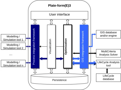
A preliminary architecture of the platform is here proposed, to face most of the interoperability requirements highlighted in the previous section, as shown in Fig. 2. Software tools (Modelling/Simulation tools) defined in Fig. 1 connect to the bus architecture for accessing the platform second-level services of technical knowledge management (optimisation module, etc.).
Specific interconnection devices are not identified here, even though the use of standard access protocols interfaces is expected to be adopted, since we are not dealing with the end-user level. The conception of the second-level platform, in fact, is not concerned with process management software. This general architecture will be specified when discussing about a possible technological solution (Fig. 4 in section 4) and finally instantiated when applied to the real industrial case (Fig. 6 in section 5).
The architecture proposed in Fig. 2 represents a conceptual solution to the scientific problems identified through the framework presented in Fig. 1. Functionalities can be defined as follows: i) coloured symbols represent different interoperability issues; ii) the dark colour (process integration) indicates the problems that will be explicitly treated in this paper; iii) the light colour (GIS integration) represents problems that will be not addressed in this paper. This latter choice is justified by the estimated level of complexity, which is greater when considering a process integration framework.
For each connection, two different perspectives are considered: model interoperability (unifying models to consider a common perspective to the interoperating software tools) and technical interoperability (including technical approaches, data formats, and interfaces).
Fig. 2 Proposed architecture for the Plate-Form(E)3
The user interface module allows the user to communicate information to the system and to state the energy-efficiency optimisation problem (optimisation criteria/objectives, constraints, etc.) provided the scale (Territorial/Plant/Process/Component) is fixed. The user can access to the different services offered by the platform and the other modules through this interface. The user interface should also provide all the necessary information for decision making; say, recalling the visualisation module to provide some relevant indicators on a dashboard.
The process integration module should be able to connect to and to call external specific tools for modelling/simulating processes defined by the user. It must be also capable to integrate all the user models coherently, without loss of information or misunderstanding. The integration, again, may occur at a territorial scale or at process/plant scale. Territorial scale problem concerns the integration in terms of multiple processes of different plants. Process/plant scale problem concerns a single process, where different components (say, e.g., heat exchangers) of the different existing simulation tools and libraries may be taken into account for its optimisation. This module is the core module for addressing the interoperability problems highlighted by the interoperation framework presented in Fig. 1.
The optimisation module is intended to solves the mono-objective or multi-objective problem defined by the user through the user interface.
The visualisation module is a platform utility deputed to give to the user a picture of the relevant indicators for decision making via the user interface. It should be based on the results of the performed optimisation service and the information derived from the models connected to the process integration module. It is clear that the data pattern adopted for
Plate-form(E)3 User interface Pro c e s s i n te g ra ti o n fra m e w o rk Persistence Modelling / Simulation tool 1 Modelling / Simulation tool 2 Modelling / Simulation tool n …. GIS database and/or engine MultiCriteria Analysis Solver LifeCycle Analysis tool LifeCycle database G IS in te g ra ti o n fra m e w o rk O pti m iz a tio n Vi s u a liz a ti o n
processing the optimisation problem is defined a priori in the optimisation module, being it an internal utility. Information coming from the GIS module can be thus adopted, if geographical data are relevant to the optimisation problem itself. Visual representation of the overall data pattern can be useful to the expert user to have a complete view of the proposed solution, thus including geographical information. The GIS integration module can be invoked using GUIs, if geographical data are relevant for solving the optimisation problem or for helping the user for decision making. In any case, geographical information should be utilised for the data pattern. Examples of the relevant data are plant locations, landscape features, such as declination or natural obstacles, energy network geographical data, transport routes, etc.
All information, regarding the functionality of PFE3 is stored in a database for the persistence of data.
3.
State-Of-The-Art on technologies for solving interoperability
problems
This section presents an overview of existing technologies, models, tools, resources and approaches that are potential candidate for solving the interoperability scientific problems identified within the framework, as defined in the previous section. For deeper technical details the reader can refer to the deliverable of the ANR Plate-Form(E)3 project [7]. The candidate technologies are foreseen as the potential conceptual bricks of the future interoperability solutions for the PFE3 platform. This paragraph thus only focuses on the basic key features of existing technologies, providing hints about the potential relevance for interoperability solutions. The outcome of the paragraph is thus a preliminary analysis for the next design step, bringing information to restrict the solution space to few technologies, as in the Fig. 3.
The Fig. 3 Erreur ! Source du renvoi introuvable.gives an overall overview of the candidate technologies with regard to the different interoperability sub-problems. Indicated relationships illustrate already existing integration between technologies (“uses” relationship). It is important to highlight that this overview considers only design problems for the Process Integration Module of PFE3, as well as the parts of PFE3 architecture that are considered as core tools – related to integrated simulation and optimisation. Each technology is analysed by providing a conclusion concerning the relevance of this technology for the PFE3 platform design.
Fig. 3 Subset of the existing technologies candidate for solving interoperability problems (adapted from [6])
3.1. Candidate technologies for the Process Integration Module
CAPE-OPEN: Open industry standard for process simulation software
CAPE-OPEN [8] is an open industry standard for interoperability of CAPE (Computer Aided Process Engineering) software tools; it is maintained by CAPE-OPEN Laboratories Network (CO-LaN). It was developed in a joint EU initiative Global CAPE-OPEN (1997-99), later also endorsed by IMS (which gave it a global reach). Initiative combined similar efforts of BP (EU project PRIMA) and BASF (German consortium IK-CAPE).
CAPE-OPEN defines rules and interfaces that allow CAPE applications or components to interoperate. This interoperation is achieved by combining the different so-called Process Modelling Components (PMC) in modelling the process in specific Process Modelling Environment (PME). PMC is a software component, which is intended to carry out a narrow, well-defined function such as the computation of physical properties, the simulation of a particular unit operation, or the numerical solution of certain types of mathematical problems arising in process simulation or optimisation. Some examples of PMCs are heat exchanger design models, pump models, distillation models, mixer/agitator calculators, safety relief of design calculators, etc. Process Modelling Environment (PME) is a software tool that supports the design of a process model either from scratch or from libraries of existing models, or both. These models allow the user to perform a variety of different tasks, such as process simulation or optimisation, using this single model of the process. Interoperation is supported by CAPE middleware, implemented by using Microsoft COM, OMG CORBA or .NET technology.
Other candidate technologies, approaches and tools Core Plate-Form(E)3 Process Integration Module ISO15926 CAPE-OPEN Modelica CLiP
OntoCAPE OSMOSE COGents
Jacaranda CERES
Based on the above conclusions, CAPE-OPEN is a very good candidate solution for syntactic interoperability of process modelling and simulation tools for the following reasons: 1) it is widely endorsed by the industries; 2) it has several standard solution for managing process models; 3) it is an open standard, so susceptible of improvement and sharing potentials; 4) it is also supported by the wide range of the different existing tools, such as Aspen, ProSim, SimSci, Belsim and many others, 5) it seems like a main candidate for a resolution of interoperability problem at process scale.
CLiP: Conceptual Lifecycle Process Model
CLiP is a comprehensive data model for process engineering [9]. It is developed with an objective to generalize, extend and integrate different existing models for chemical engineering [10].
Both interoperability problems are related to a process paradigm.
Based on the above conclusions, CLiP seems like a prime candidate for modelling chemical industry processes, since: 1) it generalizes, extends and integrates different existing models; 2) CLiP is also used as a basis for development of OntoCAPE ontological framework.
OntoCAPE: Large-scale ontology for the domain of Computer-Aided Process Engineering (CAPE)
OntoCAPE2 captures consensual knowledge of the process engineering domain in a
generic way such that it can be reused and shared. Some possible applications of OntoCAPE include: the systematic management and retrieval of simulation models and design documents; electronic procurement of plant equipment; mathematical modelling; the integration of design data from distributed sources. OntoCAPE can be characterized as a formal, heavyweight ontology, which is represented in the OWL modelling language. OntoCAPE has been subdivided in layers, which separate general knowledge from knowledge about particular domains and applications.
Based on the above conclusions, OntoCAPE is a possible candidate for the following reasoning: 1) it has an exhaustive semantic information model for data integration across the chemical process design; 2) it can be a reference for integration and management of distributed design data, namely process designs of the different plants; 3) it is relevant for territorial scale interoperability problem; 4) it is also used as reference ontology for automated decision making related to configuration of the processes (see COGents).
3.2. Candidate technologies for core functionalities of Plate-Form(E)3
Modelica: Multi-domain modelling language for component-oriented modelling of complex systems
Modelica3 is an object-oriented, declarative, multi-domain modelling language for
component-oriented modelling of complex systems, e.g., systems containing mechanical, electrical, electronic, hydraulic, thermal, control, electric power or process-oriented subcomponents. Modelica is a modelling language rather than a conventional programming language. Its classes are not compiled in the usual sense, but they are translated into objects which are then exercised by a simulation engine. The simulation engine is not specified by the language, although certain required capabilities are outlined. Based on the above conclusions, the Modelica technology is a good candidate because: 1) it is used to develop platforms that could be applied for integrated modelling and simulation; 2) it is relevant for territorial scale interoperability problem.
Examples of these platforms are OpenModelica4 and JModelica5.
OSMOSE: A tool for the design and analysis of integrated energy systems
OSMOSE6 (Acronym for Multi-Objective Optimisation of integrated Energy Systems) is
a MATLAB(C) platform designed for the study of energy conversion systems. The
platform allows linking several software, for flow sheeting (Belsim VALI, and Aspen Plus), energy integration (Easy, GLPK), optimisation (MOO), and lifecycle impact assessment (eco-invent). Among other features, OSMOSE offers a complete suite of computation and results analysis tools (optimisation, sensitivity analysis, Pareto curve analysis ...).
Based on the above conclusions, the OSMOSE technology is a possible solution because it is oriented to integrated energy management, which is a core of the interoperability problems at the territorial level.
CERES Platform
The CERES software platform is developed in scope of CERES-2 project7, funded by
ANR. Its objective is to optimise waste and heat recovery in industrial processes and achieve energy integration. It is developed in C++ and it is using OpenModelica, actually Modelica API as modelling and simulation environment.
3https://www.modelica.org/ 4https://www.openmodelica.org/ 5http://www.jmodelica.org/ 6http://leni.epfl.ch/osmose 7 http://www.agence-nationale-recherche.fr/en/research-programmes/energie-durable/systemes- energetiques-efficaces-et-decarbones/funded-project-eesi/?tx_lwmsuivibilan_pi2[CODE]=ANR-10-EESI-0001
Based on the above conclusions, the CERES platform is one of the main candidates for PFE3 because; 1) it is capable to address process-scale interoperability; 2) it has interfaces with simulation platforms (to be additionally investigated) 3) it seems that the efficiency of these interfaces could be significantly improved if CAPE-OPEN is considered as a wrapper.
3.3. Other candidate technologies, approaches and tools
ISO159268: Industrial automation systems and integration - Integration of lifecycle
data for process plants including oil and gas production facilities
While the above models consider processes in process industries as focal modelling paradigms, the ISO15926 standard [11] aims at providing artefacts for modelling technical installations and their components.
The objective of ISO15926 (developed as an extension of ISO10303/STEP principles to long-life process plants) is to facilitate effective and efficient exchange and reuse of complex plant and project information, or in specific to mitigate the current high costs of rekeying and reformatting information to move it from one proprietary system to another. It is mostly related to providing models for equipment and their properties. ISO 15926 acts like an interpreter between two otherwise incompatible systems, by translating the descriptions of plant objects from one company’s database to that of another. In doing so, the meaning of all the terms is being maintained, independently of the context.
Setup for the process industries with large projects involving many parties, and involving plant operations and maintenance could take a long time. Optimising existing processes by replacing an existing component (process-scale interoperability problem) or by adding components which could facilitate energy integration (territorial-scale) presumes procurement of the installation component or at least exchange of the information sufficient to define the requirements for this component. It is clear that establishment of the correspondences between process and equipment models could contribute to facilitating the collaboration between the relevant systems (e.g. for process modelling and procurement).
Based on the above conclusions, the ISO15926 standard is a candidate because its formal representations could reduce the efforts in making these correspondences.
COGents: Semantic approach to CAPE web service choreography
The COGents project proposed an approach to dynamic CAPE services composition [12], where a number of software agents collaborate to configure a process model, according to the users’ requirements, defined by using OntoCAPE ontology. Namely, agents are used as CAPE web services choreographers. Typical use of this approach is as following: the user defines a Modelling Task Specification (MTS) in OntoCAPE format to describe
the unit he/she requires in term of functionality and parameters (of the underlying tool, e.g. HYSYS). Then, library and match maker agents find the appropriate unit operation using the generated MTS file.
Based on the above conclusions, the COGents technology is a possible candidate since it provides an automated support for configuration/generation of process model, on demand, based on the user’s requirements.
Jacaranda
Jacaranda9 is a system for process synthesis, or automated process design, intended for
conceptual or early stage design [13]. It aims to provide the support necessary for creative and exploratory design, helping the engineer to identify the important issues and constraints for a given design problem.
Based on the above conclusions, Jacaranda is a possible solution for automated process design since: 1) it may be a candidate technology for generating cross-plant processes in territorial scale interoperability problem; 2) It is also used in COGents project as optimisation platform [12].
4.
A first deployment of PFE3 platform based on CAPE-OPEN
standard
Descending from the interoperability framework and the conclusions drawn from previous state-of-the-art, this section discusses one of the possible technologies (CAPE-OPEN) for the PFE3 platform implementation. CAPE-OPEN interfaces between CAPE (Computer-Aided Process Engineering) tools indeed; this latter has been here defined as the primary means for solving the process-scale interoperability problem of PlateForm(E)3. They are defined in EC sponsored effort (within two consecutive projects: CAPE-OPEN and Global CAPE-OPEN), with participating major industries and labs, thus gaining the global reach.
Today, CAPE-OPEN is a widely accepted approach, methodology and specification for making the different CAPE tools and components interoperable. Authors in [14] provide the list of CO-compliant CAPE tools. This list is partially exhaustive; more detailed and updated list is available at www.colan.org. The majority of the candidate tools for process modelling and simulation in PFE3 architecture already provide some level of support to CAPE-OPEN integration. However, the following architecture is only a potential architecture that is not a final choice for the project.
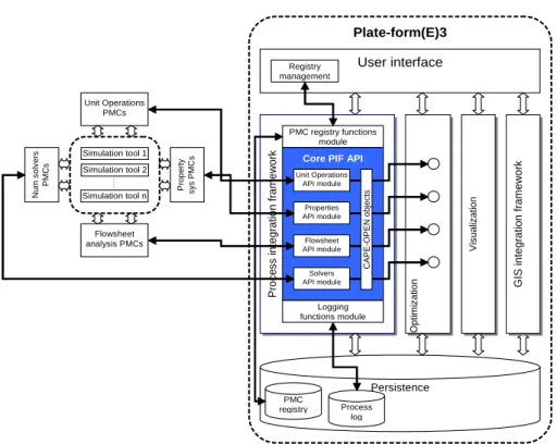
The description of CAPE objects, by CAPE-OPEN standard, is here provided together with the methodology and illustrations of some interfaces. The proposed architecture descends from the high-level architecture presented in Fig. 2. It elaborates in more detail a Process Integration Module of PFE3 platform, in the context of the possible use of CAPE-OPEN interfaces to exploit the external process modelling and simulation tools. The elaborated architecture is shown in Fig. 4.
Fig. 4 Process Integration Module architecture of PFE3 platform (figure 2) according to a CAPE-OPEN technology
Process Integration Module (PIM) is a part of the PFE3 architecture whose role is to connect to and invoke some services supplied by the external tools, used for process modelling and simulation. In context of CAPE-OPEN integration, Process Integration Module should implement functions which are using CAPE-OPEN interfaces to access the above services. The functions are part of so-called Process Integration Module Application Programme Interface (PIF API). It is here assumed that this approach would be possible only if the above tools are CAPE-OPEN compliant. This implies that, before the final selection of the technology used to implement Process Integration Module, a detailed analysis of the CO-compliance of the final choice of process modelling and simulation tools (to embed to, or to use within PFE3) is carried out.
Despite possible non-compliance situations, CAPE-OPEN must be carefully considered, since it is today’s de facto industrial standard for interoperability of process applications. In this context, the PIM would act as a CAPE-OPEN Process Modelling Environment (PME), namely a client or a socket, as it uses the CAPE-OPEN interfaces in order to request services from the external software. The process modelling and simulation tools, namely their open components, would then act as CAPE-OPEN Process Modelling Components (PMC), or servers or plug in. These are in fact applications wrapped with the CAPE-OPEN interfaces in order to expose their functionality. The list of these functions, namely contents of PIM API should be defined based on the specific interoperability use cases.
Plate-form(E)3 User interface Pro c e s s i n te g ra ti o n f ra m e wo rk Opt im iz at ion V is ual iz a tion Persistence GIS in te g ra ti o n f ra m e wo rk Simulation tool 1 …. Simulation tool 2 Simulation tool n P rop er ty sys P MC s Flowsheet analysis PMCs Unit Operations PMCs N um solv er s P MC
s Core PIF API
Unit Operations API module Properties API module Flowsheet API module Solvers API module PMC registry functions module C A P E -OP E N o bject s Logging functions module PMC registry Process log Registry management
It is clear, for the future design phase, that they should be grouped according to the PMC classes they are communicating with.
Process modelling and simulation tools being part of PFE3 provide PMC classes which can be used by Process Integration Module, namely respective API modules: Properties API module, Unit operations API module, Numerical solvers API module and Flow sheet Analysis API module. These modules are interfaces which are wrapping the native implementations of the respective relevant functions in the Optimisation module. They have to use CAPE-OPEN objects, such as Thermo, Unit, Numeric and Simulator Executive objects.
Two other modules are foreseen, to provide support functions to PIM API. PMC registry functions module facilitates adding, editing and deleting PMCs, available to PFE3 platform. Logging functions module tracks and stores all activities related to using the different PMCs of the different process modelling and simulation tools, by the platform.
5.
An application case example of the PFE3 CAPE-OPEN
configuration
The proposed CAPE-OPEN architecture configuration of the PFE3 platform is here discussed through an application to an industrial case example [15].
A Hybrid Renewable-Energy Sources system (HRESS) is considered. HRESS is a hybrid-source portable system for supplying electrical energy (up to 20kW nominal power target) mainly derived from renewable sources. The HRESS is thought to be included in a regional grid to supply energy (both electrical and thermal) to small communities (15-20 families). In this sense, the energy supply problem is to find the best configuration for energy dispatching considering the HRESS on-grid, the end users and an energy facility (electrical grid) to minimize the overall consumption.
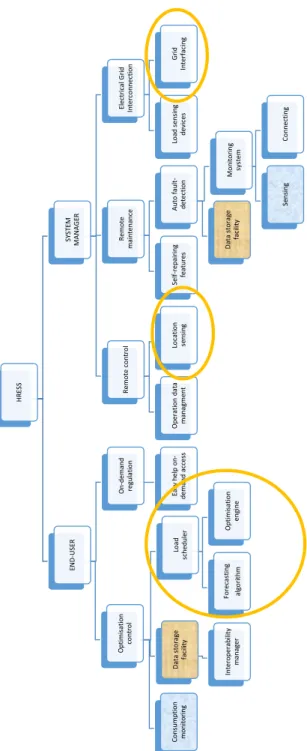
The HRESS function refinement tree is reported in figure 5. Only the external interaction partitioning was here presented according to the function and sub-functions required from the HRESS. These specifications were adopted to set the requirements for the system. The functions that are circled in orange are the modules that can be called by the platform.
Fig. 5 HRESS Function Refinement Tree HR ES S EN D -U SE R O p ti m is at io n co n tr o l Co n su m p ti o n m o n it o ri n g D at a st o ra ge fa ci lit y In tero p erab ili ty m an ag er Lo ad sc h ed u ler Fo rec as ti n g al go ri th m O p ti m is at io n en gi n e On -d em an d reg u la ti o n Ea sy h el p on -d em an d ac ces s SY ST EM M A N A G ER R em o te co n tr o l O p erat io n d at a m an ag m en t Lo ca ti o n sen si n g R em o te m ai n ten an ce Sel f-rep ai ri n g fea tu res A u to f au lt -d et ec ti o n D at a st o ra ge fa ci lit y M o n it o ri n g sy st em Sen si n g Co n n ec ti n g El ec tr ic al G ri d In ter co n n ec ti o n Lo ad sen si n g d evi ces G ri d In terf ac in g
In order to deploy the interoperability requirements in this case example, both the use-case diagram and the specifications need to be figured out. The use use-case considered the HRESS usage scenario involving one or more actors. It was traced with the purpose of describing the flow of events in detail, including how the use case starts, ends, modifies the HRESS and the interactions with actors [16]. Both level of analysis will not be reported here for the sake of brevity. In any case, the HRESS represents a software tool to be interconnected to the PFE3 platform and thus the logic behind the case example is to provide the reader with a clear view of the analysis performed in the previous paragraphs.
Actors (users) involved in the energy management case example are quite easily recognisable: they are end-user, system manager and the external grid (if any) which functions as the final sink of excess energy produced. As an alternative the grid is substituted by the external environment whenever an off-grid condition is considered. Excess production of energy – i.e. the energy that cannot be stored into the storage system – need to be dispersed into the external environment. At the use-case diagram level, the representation is quite trivial in principle, but it served to design the core component: the software module for control and optimisation of load balancing calls the PFE3 platform functions circled in figure 5: load scheduler calls for the Optimisation Module utilities; Location sensing calls for GIS service; Grid Interfacing call for the User Interface platform component.
Concerning the use case specification level, it is clear that specifications for this system may sometime be conflicting. This is because different users may access to the same source of energy, thus contemporary requiring different load paths. In terms of interoperability requirements for the platform, this fact translates into an overlap of specifications that later can turn to be an inconsistency in managing the system [17]. At the same time, another interesting situation coming out at use-case specification level is the overlapping which may occur between two end-user requests that, on the contrary, may result into a potential synergy in the energy management solution.
To provide an example, let us consider two units (buildings, facilities, etc.) deriving energy from the HRESS. The first requirement to be satisfied is to ensure a constant load for all the daylong (end user point of view), while on the same time, a minimisation of energy production discontinuities is required from the PFE3 management point-of-view. These two requirements can be apparently conflicting, since they require two opposite PFE3 reactions under a given period of time. This may thus results into an inconsistency whenever an “independent view” is adopted to the management control unit, i.e. managing each element as it was independent of the other. If the further requirement of a “system optimisation” is applied to the PFE3 platform, this latter turns the inconsistency into a positive consistency of the overall functioning of systems. Contemporary balancing the two concurrent end-user load demands can endeavour asynchronous period by switching excess energy produced to level down demand peaks: most of the time these conflicting situations can thus be solved to correctly satisfy all the load requests by the grace of systemic control logic (deputed to the Optimisation Module).
Descending from these reasoning’s it is clear that the application case example considered, even though very simple in its low level of complexity, results to be a good example of the meaning of interoperability in energy management. Multiple requirements has to be contemporary satisfied by the PFE3 platform. The multiple needs represents different interests, as expressed for instance by different requirements coming from the HRESS. The resulting consistency rules that need to be devised for the platform to satisfy
these requirements represents the design problems of the platform. In this sense this case example is here reported to explain the statements above provided concerning either the proposed framework or the criticality of the technologies to be selected for implementing PFE3.
Turning back to the case example, in the followings, the main requirements from the different stakeholders will be highlighted. In the same way, some consistency rules will be derived for the real application case example considered. By the grace of this elicitation the reader will gain the feeling of the idea proposed and the solution discussed in the present paper.
For the sake of brevity, only the elicitation phase of the Requirements Engineering (RE) process will be reported. Mainly two RE techniques were adopted: Brain Storming and Idea Reduction and Designer as Apprentice.
5.1. Requirements Definition
Bearing in mind the use case scenario of HRESS, the present paragraph makes explicit the requirements for the HRESS as a component interfaced via PFE3 platform to the territorial energy management system. Requirements thus will help to understand the “why’s” of PFE3 platform, the functions it must fulfil, and the “how’s” the same platform has to fulfil them. Requirements that came out of the expression of the external end user’s needs are expressed in a natural language, since this is a real application case. They represents the constraints for the design of the PFE3 platform.
These lists will also allow to appreciate how and if the CAPE-OPEN solution is affordable as a preliminary technology for the PFE3 implementation.
Concerning the framework classification presented in Fig. 1, it is clear that the application we are talking about concern the scale PROCESS and the Expert Domain ICT, while each of the tool features required can be modelling, simulation or optimisation depending on the specific requirement recalled.
End-User Requirements
(EUR1) ECONOMICITY: the HRESS should be run at the lowest cost as possible of the energy produced.
(EUR1.1) DATA STORAGE. It would be better to have a report of consumption data for controlling expenditures. Data management should be consistent either with the public regulation of energy consumption or with the internal maintenance modules. A statistical module for accumulating historical data is also important since this can be important to set optimal strategies.
(EUR1.2) DATA STANDARDISATION. It would be important to have recording energy supply to the local energy network for economical purposes. This requirement imply a standardisation of data collection and management with the local electrical authority.
(EUR2) SAFETY: it descends from the need for HRESS to be intrinsically stable and reliable, as well as not to cause damages to the surrounding environment. System
reliability is always a matter of proactive control of the system: this implies a strong interconnection with the maintenance module.
(EUR2.1) SIMPLICITY: it descends from the need of easy-to-use remote controlling the system.
Managing Requirements
(MGR1) USER INTERFACE: it descends from the need to easily control the system for maintenance purposes.
(MGR1.1) INTEROPERABILITY REQUIREMENTS: This requirement may deploy into several lower level requirements mainly related to the specific user application; say, e.g., the networking infrastructure, the local data management system of the infrastructure and so on which can bring several different interoperability problems with the remote control unit.
(MGR2) LOAD BALANCING: there is the need to balance loads to optimise performances, as already stated above.
(MGR2.1) PLANNER: It is important that the system has a short-term and a long-term planner module in order to run it correctly. To this aim, an adaptive strategy should be available, since there can be different load combinations that can be recovered as well as variable renewable-energy source availability.
(MGR2.2) CONTINUITY: It is important the system provides a strategy to accumulate energy reserve during load peaks.
(MGR2.3) DECISION MAKING: It is important that the system provides tools for forecasting the load path and decides the optimal energy storage strategy. This may imply the use of a simulator to forecast load paths or to prevent critical situations.
(MGR2.4) OPTIMISATION: The system should be provided with different optimisation schemes: as such, the system should provide plenty of optimisation function availabilities. Multidimensional as well as nonlinear optimisation approaches should be also possible. Finally, different optimisation variables should be available, since objective functions may change according to the specific functioning configuration of the system. Optimisation time scales should be changed accordingly.
(MGR2.5) TIME RESPONSIVENESS: The system should give a timely response as a function of the specific events. For instance peaks recovery or unexpected failure recovery are two typical situations where it is not possible to wait a scheduler to run: a recovery control strategy should then be swiftly available.
(MGR3) COORDINATED COMPONENTS OTIMISATION: there is the need to optimise storage loads and load satisfaction to optimise life cycle of the system.
(MGR3.1) TECNOLOGY CONSTRAINTS: the control unit of the system needs to be aware of technological limitations of the specific components in order to respect the optimal running cycle.
(MGR3.2) LOGISTICAL CONSTRAINTS: the control unit of the system needs to be aware of logistical limitations for the functioning of the specific components in order to forecast the operating range. For this region a location sensing information should be available on-time.
(MGR4) MICROGRID INTEROPERABILITY: the HRESS should be interfaced under different working conditions to other similar systems or to the electrical grid.
(MGR4.1) STANDARD: Communication standards between control units should be compatible.
(MGR4.2) COMMUNICATION: Loads should be controlled and
communicated appropriately in order to interface with similar systems into the grid. (MGR4.3) INTERCONNECTION: The HRESS should be synchronised with other systems. Interface should allow remote control and to respond to the same input command with a limited time of reaction and without errors.
5.2. Instantiation of the proposed architecture (Fig. 4) to the industrial example
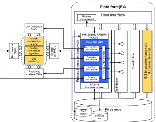
Fig. 6 Instantiation of the proposed CAPE-OPEN solution for the PFE3 architecture (ref. Fig. 4) to the application case example
Fig. 6 represents the instantiation (in orange colour) of the proposed architecture for the real application case example discussed. This case presented gives in practice the flavour of the interoperability for energy management problems to be faced.
According to the specification made for the CAPE-OPEN architecture selected for the platform proposed, its modules responds coherently to the above listed requirements in the previous paragraph. A complete check is obviously not feasible here, but it is worth to refer to (MGR4.1) requirement. Asking the PFE3 interface unit to be aware of
technological limitations of the specific components (HRESS in the specific case) in order to respect the optimal running cycle means the following actions:
A1) to know the energy management system model (control scheme and rules); A2) to know the structure of information required to run HRESS in the frame of the specific application considered;
A3) to let HRESS interoperate with other devices (say electrical grid for instance) so as to coordinate the energy flow exchange.
The selected CAPE-OPEN solution of the platform clearly responds to these needs, since referring to CAPE tools means to have standard system models and simulation tools. This means to simplify the complexity of A1 action, while having a clear view for the A2 action. The quality of Optimisation module and interfacing unit of the PFE3 platform is not provable here (action A3) in detail, but it is clear how the reference to a common standard for the most of the applications interfacing within the platform may ensure an easier approach to A3 action.
In particular, the CAPE-OPEN solution seems interesting as the platform may be appropriate to respond at the different scale level (process or territorial) above discussed.
6.
Conclusions and Future Works
The work presented in this paper is a first step in the design of a software platform (PFE3 project) having the scope to address the sustainability energy production and use efficiency.
An appropriate interoperability framework intended to support the design of the PFE3 platform is discussed. The architecture proposed is intended to interconnect different energy system components is a software bus, to allow a second level interfacing system among the different energy generation/use management systems. The optimisation modules of the platform have several purposes: optimisation at different scales (namely component, plant and territory), interfacing, and localisation.
Following an extensive state-of-the-art analysis, a first architecture is presented by specifying the possible second level structure of modules. It was devised based on CAPE-OPEN standard.
The real application case example discussed shows that: i) identified interoperation issues are actual, and ii) the proposed platform architecture is coherent for addressing energy efficiency problems.
This proposed architecture will not be implemented yet in the Plate-Form(E)3 project due to strategic choices such that preserving a core architecture based on OSMOSE. A future research project could be proposed for enriching the developed PFE3 prototype (at the end of the project) with the CAPE-OPEN standard such that new CAPE-OPEN compliant tools can easily connect to the platform.
Acknowledgement
This work has been partially funded by the program SEED 2012 from the French National Agency for Research ANR in the frame of the Plate-Form(E)3 project and the PICS
CNRS n°6361/195098 "Interoperability assessment for production systems sustainability", CNRS/Politecnico di Bari project.
7.
References
1. A. Aubry, H. Panetto. Towards interoperability properties for tooling a software bus for energy efficiency. 4th International Conference on Information Society and Technology, ICIST 2014, Kopaonik, Serbia. 1, pp.285-291, 2014.
2. IEEE. IEEE Standard Computer Dictionary: A Compilation of IEEE Standard Computer Glossaries. Institute of Electrical and Electronics Engineers, 1990. ISBN: 1559370793 3. J. Sowa. Knowledge Representation: Logical, Philosophical, and Computational Foundations,
CA:Brooks/Cole Publishing Co. 2000
4. E. Yahia E, A. Aubry, H. Panetto. Formal measures for semantic interoperability assessment in cooperative enterprise information systems. Computers in Industry 63:443–457. (2012). 5. INTEROP, Enterprise Interoperability-Framework and knowledge corpus - Final report,
INTEROP NoE, FP6 – Contract n° 508011, Deliverable DI.3, May 21st 2007.
6. A. Aubry, J. Noel, D. Rahon, H. Panetto. A cross-scale models interoperability problem: the Plate-Form(E)3 project case study. 3rd industry Applications and Standard initiatives for Cooperative Information Systems for Interoperable Infrastructures, Sep 2013, Graz, Austria. Springer, OTM 2013 Workshops. LNCS 8186, pp. 57-61, Lecture Notes in Computer Science. 2013
7. A. Aubry. Plate-form(E)3 Deliverable 1.3 - State-of-the-art concerning connectivity of software tools.
8. J.P. Belaud, M. Pons. Open software architecture for process simulation: The current status of CAPE-OPEN standard. Computer Aided Chemical Engineering. Volume 10, pp. 847–852, 2002.
9. B. Bayer, W. Marquardt. Towards integrated information models for data and documents. Computers & Chemical Engineering. Volume 28, Issue 8, pp 1249–1266, 2004.
10. B. Bayer, R. Schneider, W. Marquardt. Integration of data models for process design - first steps and experiences. Computers & Chemical Engineering. Volume 24, Issues 2–7, pp 599– 605, 2000.
11. R. Batresa, M. Westb, D. Lealc, D. Priced, K. Masakia, Y. Shimadae, T. Fuchinof, Y. Nakag. An upper ontology based on ISO 15926. Computers & Chemical Engineering, Volume 31, Issues 5–6, pp. 519–534, 2007.
12. B. Braunschweig, E. Fraga, Z. Guessoum, W. Marquardt, O. Nadjemi, D. Paen, D. Piñol, P. Roux, S. Sama, M. Serra, I. Stalker, A. Yang. CAPE web services: The COGents way. Computer Aided Chemical Engineering. Volume 18, pp 1021–1026, 2004.
13. E.S. Fraga, M.A. Steffens, I.D.L. Bogle, A.K. Hind. An object-oriented framework for process synthesis and optimization. Fifth International Conference on Foundations of Computer-Aided Process Design. pp. 446 – 449, 2000.
14. J.M. Nougues, D. Piñol, J.C. Rodríguez, S. Sama, P.Svahn. CAPE-OPEN as a mean to achieve interoperability of Simulation Components. 45th International Conference of Scandinavian Simulation Society, SIMS 2001.
15. S. Bruno, M. Dassisti, M. La Scala, M. Chimienti, C. Cignali,, E. Palmisani. Predictive Dispatch Across Time of Hybrid Isolated Power Systems. IEEE Transactions on Sustainable Energy, vol. 5, p. 738-746, 2014. ISSN: 1949-3029, doi: 10.1109/TSTE.2013.2295428 16. J. Poelmans, G. Dedene, M. Snoeck, S. Viaene. An iterative requirements engineering
framework based on Formal Concept Analysis and C–K theory. Expert Systems with Applications 39.9 (2012): 8115-8135, 2012.
17. G. Spanoudakis, A. Finkelstein, D. Till. Overlaps in requirements engineering. Automated Software Engineering. 6.2 (1999): 171-198, 1999.
18. Panetto H. Towards a classification framework for interoperability of enterprise applications. International Journal of Computer Integrated Manufacturing 20/8:727–740. 2007 doi: 10.1080/09511920600996419
![Fig. 1 Conceptual Interoperation framework, adopted to classify scientific problems faced by an expert (updated from [6])](https://thumb-eu.123doks.com/thumbv2/123doknet/14287413.492265/5.892.191.686.230.539/conceptual-interoperation-framework-adopted-classify-scientific-problems-updated.webp)
![Fig. 3 Subset of the existing technologies candidate for solving interoperability problems (adapted from [6])](https://thumb-eu.123doks.com/thumbv2/123doknet/14287413.492265/10.892.189.710.212.514/subset-existing-technologies-candidate-solving-interoperability-problems-adapted.webp)