HAL Id: hal-02139772
https://hal.archives-ouvertes.fr/hal-02139772
Submitted on 25 May 2019HAL is a multi-disciplinary open access
archive for the deposit and dissemination of sci-entific research documents, whether they are pub-lished or not. The documents may come from teaching and research institutions in France or abroad, or from public or private research centers.
L’archive ouverte pluridisciplinaire HAL, est destinée au dépôt et à la diffusion de documents scientifiques de niveau recherche, publiés ou non, émanant des établissements d’enseignement et de recherche français ou étrangers, des laboratoires publics ou privés.
Entire Life Time Monitoring of Filament Wound
Composite Cylinders Using Bragg Grating Sensors: III.
In-Service External Pressure Loading
Hilario Hernández-Moreno, Francis Collombet, Bernard Douchin, Dominique
Choqueuse, Peter Davies
To cite this version:
Hilario Hernández-Moreno, Francis Collombet, Bernard Douchin, Dominique Choqueuse, Peter Davies. Entire Life Time Monitoring of Filament Wound Composite Cylinders Using Bragg Grat-ing Sensors: III. In-Service External Pressure LoadGrat-ing. Applied Composite Materials, SprGrat-inger Verlag (Germany), 2009, 16 (3), pp.135-147. �10.1007/s10443-009-9082-x�. �hal-02139772�
e note th at this is an aut hor-pr oduc ed PDF of an article a cce pted for publ icatio n foll owin g pe er revi ew. T he defin iti v e pu b lish e r-a uthentic ated ve rsion is av ail a b le on the pub lis her W eb site l
Applied Composite Materials
June 2009, Volume 16, Number 3 : Pages 135-147
http://dx.doi.org/10.1007/s10443-009-9082-x © 2009 Springer. Part of Springer Science+Business Media
The original publication is available at http://www.springerlink.com
Archimer, archive institutionnelle de l’Ifremer
http://www.ifremer.fr/docelec/
Entire Life Time Monitoring of Filament Wound Composite Cylinders
Using Bragg Grating Sensors: III. In-Service External Pressure Loading
H. Hernández-Moreno1, 2, F. Collombet1, *, B. Douchin1, D. Choqueuse3 and P. Davies3
1
Université de Toulouse; INSA, UPS, Mines Albi, ISAE; ICA (Institut Clément Ader), IUT P. Sabatier, 133c, avenue de Rangueil, 31077 Toulouse, France
2
Instituto Politécnico Nacional, ESIME Unidad Ticomán, Av. Ticomán No. 600, Col. San José Ticomán, 07340 México D. F., México
3
IFREMER, Materials & Structures group, Brest Centre, BP70, 29280 Plouzané, France
*: Corresponding author : F. Collombet, email address : francis.collombet@iut-tlse3.fr
Abstract:
This article is the third of three papers describing a study of the monitoring of filament wound composite cylinders for underwater applications. Part I described the technological issues and the development of specimens instrumented with embedded gratings and thermocouples, with the aim of monitoring the temperature and strain changes during the cylinder manufacturing presented in Part II. Residual strains are not negligible, over 1,000 axial micro-strain at the end of the curing cycle. Part III describes the response of these cylinders to hydrostatic pressure loading. The same embedded fiber optical Bragg gratings (FBGs) used for parts I and II of the study are here used as strain gauges. Their response is compared to that of classical resistive strain gages bonded to the inner surface of the tube. Results from these initial tests demonstrate the embedded FBG sensor’s capability to monitor structural health of an underwater structure from fabrication throughout its service life. Embedded instrumentation records strains during pressure cycles up to final failure, without affecting the cylinder response.
Keywords: Polymer-matrix composites (PMCs) - Smart materials - Residual stress - Filament winding - Underwater application
1. Introduction
Composite materials are well suited for underwater applications, where their light weight and excellent corrosion resistance make them an attractive alternative to metallic materials. Several authors have shown that composite cylinders can be used to resist the hydrostatic pressures which accompany deep sea applications [1-6]. If such applications are to become more widespread, particularly for the offshore oil industry, it is essential to be able to monitor the material condition during manufacturing and then throughout the service life. Two previous papers in this series [7] [8] have shown how a filament wound composite cylinder can be instrumented with Bragg gratings, which enable its condition during and after manufacture to be evaluated. In the present paper one of those cylinders, which was previously monitored during fabrication, is subjected to increasingly high external pressure cycles up to failure, in order to demonstrate how monitoring can be performed in service. The test was carried out at the hyperbaric testing facility at IFREMER, the French Ocean Research Institute. The pressure which acts on an immersed structure depends on the depth according to the expression [9]:
P = C1*H + C2 * H2 (1)
where P = pressure (MPa), H = immersion depth (m), C1 is equal to 0.01 MPa/m and C2 equal to 0.05 x 10⁻⁶ MPa/m². For deep sea applications this loading is often the main design criterion.
In recent years optical fiber based sensors, such as Bragg gratings, have been increasingly used for in situ strain and temperature monitoring, references can be found in the previous papers [7] [8]. One example developed specifically for underwater applications was described by Brower [10], who presented a “smart pipe system” composed of a “smart layer” (composite material) with embedded Bragg gratings, placed between the pipe outer skin and the thermal insulation layer, this system allows pipe monitoring during service.
Several recent publications have described the response of glass/epoxy composite cylinders to external pressure [11-14]. Two failure modes can occur; buckling, usually associated with thin walled tubes, and material failure in compression observed in thicker cylinders. Figure 1 shows the two failure regions, together with some IFREMER data for 55° glass/epoxy cylinders. The limit between the two modes depends on the choice of failure criteria, both for buckling and material failure, and there is still considerable debate over the appropriate choice for this type of loading [15]. An analytical expression for buckling proposed by Mistry et al. [16] is plotted in Figure 1, together with a simple maximum hoop stress criterion for which the critical value is taken as 500 MPa for material failure. Given the uncertainty in predicting implosion pressures most applications rely on qualification testing. This is performed in pressure vessels, on tubes which are closed by metallic end plates. The design of these end closures, which determine the test boundary conditions, is particularly important when thick wall tubes are tested if premature failure is to be avoided [17] [18]. In a test cylinder, strain sensors (strain gages) are placed on the structure at the moment when the specimen is being prepared for testing, so the initial strain within the material is unknown, though sometimes it can be estimated. One aim of the present study is to include the specimen residual strain, which is measured during fabrication, in the design of the pressure vessel. For this it was necessary to demonstrate that the same Bragg gratings could be used to follow both manufacturing and pressure testing.
2. Testing
2.1. Cylinder characteristics
A first series of five cylinders without instrumentation was pressure tested to failure in order to establish the reference baseline. These were nominally identical to the instrumented specimens, filament wound on the same machine with the same winding parameters, and have been reported previously [19]. All were 4.4 mm thick, 125 mm internal diameter,
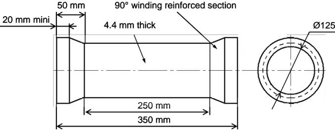
reinforced with 3.5 mm width glass fibre rovings (1200 tex). The epoxy resin system used is a mixture of Araldite LY 5052 and hardener HY 5052. Winding angle is ±55° with respect to the cylinder axis. The number of layers is 7 (one filament wound layer is composed of the equivalent of two unidirectional layers, at +55° and –55°). The specimen has zones of reinforcing fibers at both ends with a winding angle of 90°. These allow plane surfaces to be obtained by a machining operation in order to form the interfaces with metallic closures (Figure 2), [20]. The instrumented specimen used for pressure testing here was cylinder 37 (see Part II [8]), which has one rhomboid pattern in the circumferential direction. The Bragg gratings are located at mid-length of the cylinder, between the first and second reinforcement layers near the inner surface. Based on the results from previous tests (Figure 1) these are thin wall cylinders with a t/d ratio of 0.035, and would be expected to fail during pressure testing by buckling.
2.2. Sensor characteristics
Bragg grating sensors have a central wavelength B (Bragg wavelength). Temperature
variation T, and longitudinal strain , both produce a wavelength shift B (Kang [21]);
grating behavior can be written as equation 1 with aB, and bB being the sensitivities to
temperature and strain respectively:
b T a B B (1)The technique used in this research for decoupling strain and temperature responses is to perform an initial characterization of the thermo-optical sensor response before embedding. Once the thermal response is known, the strain can be obtained using equation 2. A complete description of calibration procedures is presented in Part II [8].
(
T
)
b
B
reading
1
(2)The Bragg grating wave length response to temperature excitation is linear, so with calibration data a linear regression can be obtained for each grating, having the form of equation 3:
(
T
)
m
T
b
(3)where, m is the slope in the wavelength vs. temperature graph, and b is the ordinate to origin.
Substituting equation 3 into equation 2 leads to equation 4:
m
T
b
b
B reading
1
(4)wherereading is obtained from the Bragg grating interrogator system and T is the actual
temperature at the place where Bragg grating is located. This temperature is obtained by embedding, beside each grating, a small diameter (250m) K type thermocouple, to provide a temperature reference. If “bB” (strain sensitivity) has a value of 1.21 pm/°C, for a Bragg wavelength of 1550 nm, the constant “b” has a value of 7.80.10-7/ [22].
The details of the two Bragg grating sensors embedded in the cylinder tested under external pressure are given in Table 1. As indicated in Part I, [7] the length of the Bragg gratings is 10 mm and they are UV uniformly inscribed with a phase mask and apodization in a 125 m diameter optical fiber having a polyacrylate coating (SMF-28e®). Each grating measures a mean strain value over the sensor length.
2.3. Test characteristics and cylinder conditioning
Cylinder 37 was tested under external pressure to validate embedded instrumentation during service and to continue the monitoring of a composite filament wound structure until failure. Taking into account the failure mode of cylinders under pressure (buckling) the sensor must be placed on the structure at the adequate location in order to be sensitive to the resulting deformation. The sensor was therefore placed in the mid-section of the cylinder, between the first and the second ply of the structure. In plane deformations of the central part of the cylinder correspond to the sum of the global compression deformation of the structure and the flexural deformation induced by the buckling mode of the structure. The flexural deformations of the ring induced by the buckling of the structure for the more common mode-shapes (modes 2 and 3) are shown in figure 3a and 3b. This indicates that the flexural deformation depends on:
the localization of the sensor along the circumference of the ring, the distance of the sensor from the neutral fibre of the beam.
The response to flexural deformation of a sensor will be zero if it is placed at a node point of the mode-shape and maximum at the anti-node point, Figure 3c. In the same way the sensor placed on the surface of the material (outer or inner) will have the maximum sensitivity to the flexural deformation while a sensor placed at the mid thickness of the material will not measure any bending strain. In this initial study to validate the use of embedded optical sensors the cylinder was equipped with two Bragg gratings, one placed in the axial direction and the second lying along the circumference, as shown in Figure 4a. Results from fabrication monitoring indicated the presence of residual strains. Residual strains at 21°C for this cylinder at the end of manufacturing were: in the axial direction -1025 , in the circumferential direction 70. For this test, one end closure was provided with a sealed passage tube, in order to connect the optical fibers to the chamber cover. In order to monitor strains during the entire service life of the structure (up to 10 years for some underwater applications) the optical fiber must be carefully protected from the external environment. The main objectives are:
To protect the fiber from hydrolytic attack. Glass fiber is very sensitive to water contact, which may induce stress corrosion cracking;
To leave the non embedded part of the optical fiber free of pressure in order to avoid parasite effects induced by pressure acting on the fiber.
Based on experience from previous projects at Ifremer these two points were solved by placing the optical fiber in a small diameter stainless steel tube capable of withstanding the hydrostatic pressure.
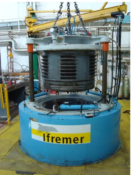
This cylinder was also instrumented with strain gages to compare with the Bragg grating results. These were bonded on the inner surface of the cylinder, three in the circumferential direction and three in the axial direction, but only one of the latter functioned correctly during the test. These are also shown on Figure 4a. The conditioned cylinder before testing is shown in figure 4b. The test was performed using the 1000 bar capacity hyperbaric testing chamber shown in figure 5.
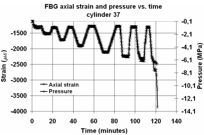
Loading and unloading pressure cycles were applied, Figures 6 and 7, with pressure increments of 10 bar, starting at 10 bar. Once the pressure had stabilized at 10 bars, the first loading – unloading cycle was composed of a pressure ramp until 20 bar, followed by a constant pressure segment lasting 5 minutes and an unloading ramp to 10 bars. Subsequent cycles have the same shape, but each time the final value is higher by 10 bar. The loading and unloading rate was 1 MPa/min for the first 4 cycles (up to 5 MPa) then increased to 3 MPa/min for the last 3 cycles (up to collapse). During the entire test, strain responses from gages and pressure signals are recorded with a data acquisition system, with a sampling frequency of 4 readings per minute. This sampling frequency is limited by the data acquisition program available, which was developed to interrogate a large number of strain gages inside the pressure vessel via a single connecting cable. Central Bragg grating wavelengths were recorded continuously using a different acquisition system with a higher frequency of 5 Hz. Bragg grating wavelengths are transformed into strains following the
procedure described in section 2.2. Spectra of both gratings were also recorded at different times during the test, in order to check that there was no influence of transverse loading on the optical fiber strain.
3. Test results
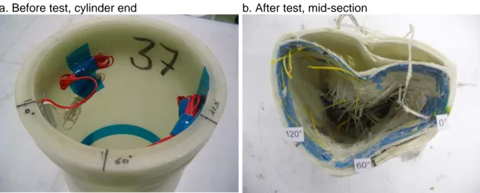
Results from the five initial tests to failure indicated a mean value of implosion pressure of 6.5 MPa, with a standard deviation of 0.4 MPa (Table 2), as described previously [19]. In all but one case the cylinders buckled with a 3-lobe circumferential failure mode. The implosion pressure for the test on the cylinder with the Bragg grating was 6.7 MPa, which is within one standard deviation of the mean value obtained on non-instrumented specimens, and showed the same 3-lobe buckling failure mode, Figure 8. This result indicates that the embedded instrumentation has no significant influence on mechanical strength at implosion.
3.1. Bragg grating strain response to pressure
Spectral response of both gratings (axial and circumferential) were recorded at specific points during the test, specifically before and after pressure vessel closure and at the different pressure steps (10, 20, 10, 30, 10, 40, 10, 50, 55, 60, 10 Bar), in order to check for any spectrum shape variation. Examples of circumferential grating spectra are shown in Figure 9, the axial spectra are very similar. Analyzing spectral response it can be seen that throughout the test, the shape of spectra does not vary, this means that loads transverse to the optical fiber axis do not influence the grating response significantly, so the grating response is solely due to membrane strains and temperature (in this case the latter is almost constant).
The Bragg grating strain response is initially proportional to pressure (Figures 6 and 7), but for the last three cycles there is a slight deviation, which may indicate a change in shape due to buckling or damage initiation. Bragg grating data is recorded for slightly longer than the pressure data at rupture due to the difference in sampling periods, 15 s for the pressure gage and 0.2 s for Bragg gratings, indicating the functionality of the latter until the last moments of the specimen life.
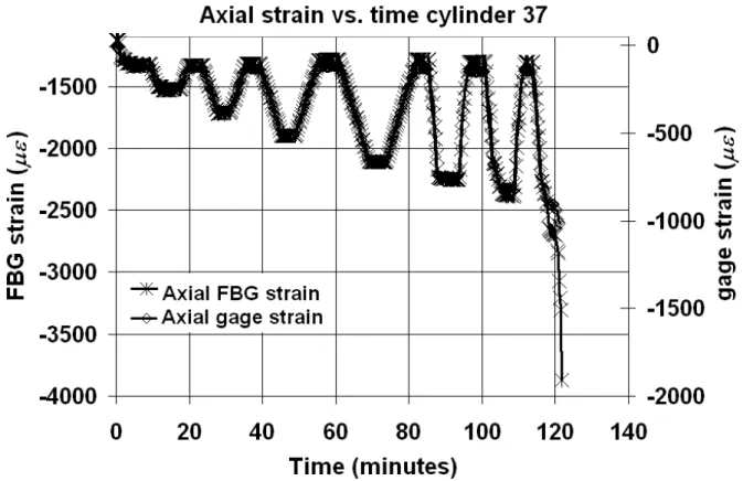
3.2. Bragg grating strain response and gage strains
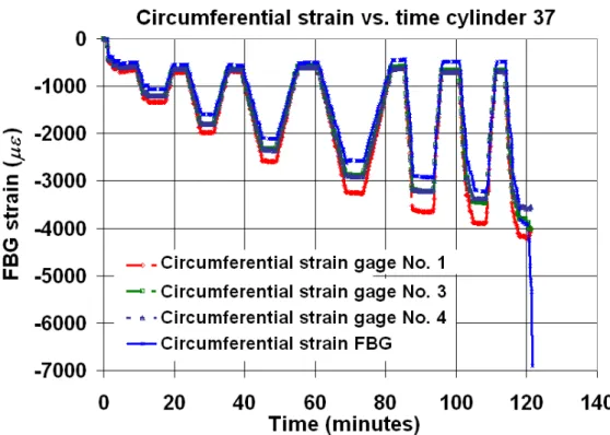
The Bragg grating and strain gage responses show similar behavior (see Figures 10 and 11). As noted with respect to pressure, the Bragg grating strain during the last three cycles shows a small deviation compared with the strain gage values. As previously noted the absolute values measured will depend on the location of the measurement points with respect to the buckled shape. As the lobes develop some regions are more highly strained while others are unloaded, due to the induced local flexure. Only three strain gages were bonded round the circumference in this test, and this is not sufficient to represent the evolution of the buckled shape accurately. In order to be sure to capture the buckling mode correctly a larger number of strain gages are needed, and in some large cylinder tests over 100 can be used. In the axial direction the strain gage begins with an almost zero value while the Bragg grating already has 1128 Figure 8). This is due to the fact that the Bragg grating followed the strain evolution from fabrication including residual strain. In the circumferential direction (see Figure 7), this difference is not obvious because the residual strain indicated by the Bragg grating at the beginning is only 21. It is important to note that these residual strains evolved very little (by around 100 micro-strain) in the time between the end of manufacture and the start of the pressure test (6 months). This indicates that these are indeed permanent residual strains, which must be taken into account in cylinder design.
When pressure-strain diagrams are analyzed (Figures 12 and 13), a critical pressure can be observed around 5.5 MPa (the pressure at which the pressure versus strain plot becomes non-linear). Beyond this point, a Bragg grating hysteresis response is observed, which is not detected by the strain gages. The reasons for this hysteresis are not clear, more tests are required to investigate its origins. Observing each diagram between 0 and 5 MPa (before pressure reaches a critical value), the Bragg grating strain response follows a very similar slope to that of the strain gages, within the variations between the strain gages (due to different flexural strains at different points on the mode-shape as indicated in Figure 3c).
3.3. Future instrumentation strategy
One of the major advantages of Bragg grating strain measurements for in-situ measurements is the possibility to place several strain measurement points on the same fibre, significantly reducing the number of cables and connectors. For example, multi sensor fibres can be implanted during cylinder manufacture with six sensors equally distributed along the sensitive zone in order to detect either a 2-nodes mode-shape (over half the circumference of the central part) and a 3 node mode-shape (over one third of the circumference). In addition, if embedded fibre optic sensors can also be implanted at the neutral fibre the comparison with the results from sensors placed close to the surface would enable compression strains to be distinguished from flexural (buckling) deformation. This comparison may also provide information on the distribution of residual stresses through the thickness of the structure. It should be noted however, that in this study Bragg gratings have only been tested up to 7 MPa. For higher pressures (deeper marine applications) the connectors and FBG response must be verified.
4. Conclusion
The results from an external pressure test in a hyperbaric chamber indicate that embedded optical fiber instrumentation allows real time material monitoring within the structure. The presence of the instrumentation has no influence on failure mode nor on implosion pressure, at least for the cylinder conditions studied here. In-situ fiber optic instrumentation is a valuable tool to provide a complete record of the evolution of cylinder response, in terms of strain and temperature, from fabrication throughout the service life. The residual strains which appear during manufacture are not negligible (over 1100 axial micro-strain for the tube tested here) and may significantly affect subsequent behaviour during service. If reliable predictive models are to be developed for deep sea pressure vessel applications these strains must be included in failure criteria, and Bragg grating instrumentation provide the means to quantify them. They may also enable manufacturers to evaluate strategies to reduce these residual strains, by optimizing cure cycles.
Acknowledgments
H. Hernández Moreno wishes to thank the National Council of Science and Technology of Mexico (CONACYT) and the National Polytechnic Institute of Mexico (IPN) for their scholarship sponsoring. The authors thank I. Fernandez Hernandez, J. Bauw, F. Afonso, and E. Vargas Rojas for their collaboration during their internship at LGMT. Also thanks to M. Mulle at LGMT, for his collaboration during the instrumented implosion test, and to IFREMER for financial and technical support, with special thanks to P. Warnier and A. Duff.
References
1. Stachiw JD, Frame B, Graphite fiber reinforced plastic pressure hull mod 2 for the advanced unmanned search system vehicle, Tech Report 1245, Naval Ocean Systems Center, San Diego, 1988.
2. Smith CS, Design of Marine Structures in Composite Materials, Elsevier Applied Science, 1990.
3. Stevenson P, Graham D, Clayson C, The mechanical design and implementation of an autonomous submersible, J. Soc. For Underwater Technology, 23, 1, 1998 pp 31-41.
4. Graham D Composite pressure hulls for deep ocean submersibles, Composite Structures, Volume 32, Issues 1-4, 1995, pp 331-343.
5. Gruber MB, Lamontia MA, Smoot MA, Peros V, Buckling performance of hydrostatic compression loaded 7-inch diameter thermoplastic composite monocoque cylinders, J. Thermoplastic Composite Materials, 1995, Vol. 8, January, pp 94-108.
6. Davies P, Riou L, Mazeas F, Warnier P, Thermoplastic composite cylinders for underwater applications, Journal of Thermoplastic Composite Materials, Sept 2005, 18 (5), 417-431.
7. Hernández-Moreno H, Collombet F, Douchin B, Choqueuse D, Davies P, González Velázquez JD, Entire life time monitoring of filament wound composite cylinders using Bragg grating sensors: I. Adapted tooling and instrumented specimen, submitted to Applied Composite Materials, 2009.
8. Hernández-Moreno H, Collombet F, Douchin B, Choqueuse D, Davies P, González Velázquez JD, Entire life time monitoring of filament wound composite cylinders using Bragg grating sensors: II. Process monitoring, submitted to Applied Composite Materials, 2009. 9. AFNOR standard XP X 10-812, Marine environment, oceanographic equipment, environmental test and recommendations for test equipment 1995.
10. Brower DV, Structural properties measurements in deepwater oil and gas fields using an advanced fiber optic sensor monitoring system. SAMPE Journal 2005; 41(5): 6-9.
11. Hinton MJ, Soden PD, Kaddour AS, Strength of composite laminates under biaxial loads, Appl. Comp. Mats., 3, 1996, 151-162.
12. Davies P, Carlsson LA, Influence of delamination on strength of externally pressurized glass/epoxy cylinders, AMD-Vol 235, Thick Composites for load bearing structures, ASME, 1999, 97-104.
13. Soden PD, Hinton MJ, Kaddour AS, Biaxial test results for strength and deformation of a range of E-glass and carbon fibre reinforced composite laminates, Comp. Sci & Tech., 62, 2002, pp1489-1514.
14. Gning PB, Tarfaoui M, Collombet F, Riou L, Davies P, Damage development in thick composite tubes under impact loading and influence on implosion pressure: experimental observations, Composites Part B: Engineering, Volume 36, Issue 4, June 2005, pp 306-318. 15. Soden PD, Kaddour AS, Hinton MJ, Recommendations for designers and researchers resulting from the world-wide failure exercise, Composites Science and Technology, Vol. 64, Issues 3-4, March 2004, pp 589-604.
16. Mistry J, Gibson G, Wu Y-S, Failure of composite cylinders under combined external pressure and axial loading, Composite Structures 1992, 22, (4), pp 193-200.
17. Blake HW, Starbuck JM, A shear deflection theory for analysis of end plugs for external pressure tests of composite cylinders, ASTM STP 1185, 1994, pp 113-136.
18. Davies P, Le Flour D, Long term behaviour of fibre reinforced structures for deep sea applications Proc. 3rd Oilfield Engineering with Polymers conference, RAPRA, 28-29 Nov. 2001, London, p255-268.
19. Hernández-Moreno H, Douchin B, Collombet F, Choqueuse D, Davies P, Influence of winding pattern on the mechanical behavior of filament wound composite cylinders under external pressure, Composites Science and Technology, 2008, Vol. 68, 3-4, pp 1015-1024.
20. Hernandez-Moreno H, Monitoring de la fabrication de tubes composites réalisés par enroulement filamentaire et comportement mécanique sous pression externe, PhD Thesis (in French), Paul Sabatier University, Toulouse, 2006, p. 1-238.
21. Kang HK, Park JS, Kang DH, Kim CU, Hong CS, Kim CG, Strain monitoring of a filament wound composite tank using fiber Bragg grating sensors, Smart Mater Struct., 2002, Vol. 11, Issue 6, p. 848–853.
22. Mulle M, Zitoune R, Collombet F, Olivier P, Grunevald Y-H, Thermal expansion of carbon–epoxy laminates measured with embedded FBGS – Comparison with other experimental techniques and numerical simulation, Composites Part A: Applied Science and Manufacturing, 2007/05, Vol. 38, 5, p. 1414-1424.
Figures
Cylinder failure modes
0 500 1000 1500 0 0.02 0.04 0.06 0.08 0.1 0.12 thickness/diameter Im p los ion pr es s ur e , bar s
Max. Hoop stress Buckling (Mistry[16]) Test data
t/d = 0.035
BUCKLING
MATERIAL FAILURE
Figure 1. Implosion pressure versus thickness to mean diameter (t/d) ratio, showing transition between buckling and material failure modes.
Ø125
250 mm
350 mm
20 mm mini
50 mm
90° winding reinforced section
4.4 mm thick
Ø125
250 mm
350 mm
20 mm mini
50 mm
90° winding reinforced section
4.4 mm thick
250 mm
350 mm
20 mm mini
50 mm
90° winding reinforced section
4.4 mm thick
Figure 2. General dimensions of specimen with machined ends.
(a) (b)
Distance to neutral fibre
NODE POINT (high flex strain)
ANTI-NODE
(low flex strain)
Figure 3. a) Mode 2, b) Mode 3 mode-shapes and c) Strain sensitivity at different points.
(a)
(b)
sealed passage conduit
cylinder
metallic closure
sealed passage conduit
cylinder
metallic closure
Figure 4. Instrumented cylinder with a) Strain and temperature measurement points, b) Complete cylinder and closure system before external pressure testing in hyperbaric chamber.
a. Before test, cylinder end b. After test, mid-section
Figure 11. Bragg grating and strain gage response in circumferential direction.
Figure 13. Circumferential pressure-strain plots.
Tables
Table 1. Bragg grating temperature response and metrological characteristics. Cylinder directions for
OFBG placement Nominal wavelength (nm) m(nm/°C) b(nm) a (10
-6/°C) sensitivity (nm/°C)
axial 1535.155 0.0103 1534.974 6.7 0.0103
circumferential 1550.055 0.0105 1549.900 6.7 0.0105
Table 2. Results from external pressure tests
Cylinder Implosion pressure (MPa) Buckling mode Non-instrumented [19] 6.0 6.8 6.5 6.4 6.7 2 3 3 3 3 FBG Instrumented (No. 37) 6.7 n=3