READ THESE TERMS AND CONDITIONS CAREFULLY BEFORE USING THIS WEBSITE. https://nrc-publications.canada.ca/eng/copyright
Vous avez des questions? Nous pouvons vous aider. Pour communiquer directement avec un auteur, consultez la première page de la revue dans laquelle son article a été publié afin de trouver ses coordonnées. Si vous n’arrivez pas à les repérer, communiquez avec nous à PublicationsArchive-ArchivesPublications@nrc-cnrc.gc.ca.
Questions? Contact the NRC Publications Archive team at
PublicationsArchive-ArchivesPublications@nrc-cnrc.gc.ca. If you wish to email the authors directly, please see the first page of the publication for their contact information.
NRC Publications Archive
Archives des publications du CNRC
Access and use of this website and the material on it are subject to the Terms and Conditions set forth at
New housing and airport noise
Quirt, J. D.; Walton, A.
https://publications-cnrc.canada.ca/fra/droits
L’accès à ce site Web et l’utilisation de son contenu sont assujettis aux conditions présentées dans le site
LISEZ CES CONDITIONS ATTENTIVEMENT AVANT D’UTILISER CE SITE WEB.
NRC Publications Record / Notice d'Archives des publications de CNRC:
https://nrc-publications.canada.ca/eng/view/object/?id=bfa03af7-c3a0-4eca-8bd5-202b8174e91e https://publications-cnrc.canada.ca/fra/voir/objet/?id=bfa03af7-c3a0-4eca-8bd5-202b8174e91eNew Housing
1+
New Housing
and Airport Noise
Price: $2.00
First edition 1976 Metric edition 1978 Revised 1979 Revised 1981
Prepared in cooperation with the Division of Building Research of the National Research Council of Canada.
Canada Mortgage
and Housing Corporation Honourable Paul Cosgrove
Societe canadienne
ISBN 0-660-50724-2 Cat. No. NH17-6/1981
New Housing and Airport Noise
A supplement to the Site Planning CriteriaSection A Section B Section C Section D Section E Table 1 Table A Table B TableC Table D Table E Section F Appendix A Appendix B AppendixC Appendix D Appendix E Contents Introduction. . . 1 The noise prol:flem near airports: its evaluation 3 Classification of areas adjacent to airports. .. .. 5 NEF contour maps and their use ... 6 Adequate sound insulation ... 8 Required Acoustic Insulation Factor ... 8 Acoustic Insulation Factor for various types of window... 10 Acoustic Insulation Factor for various types of exterior wall ... 11 Acoustic Insulation Factor for various ceiling-roof combinations ... 12 Acoustic Insulation Factor for various types of exterior doors ... 12 Component area percentage relative to total
floor area of a room ... 13 f'
Design advice ... 14 Calculating Acoustic Insulation Factor from
laboratory data ... 16 Derivation of Table 1 ... 19 Associated ventilation needs. . . .. 20 Adjustments to the basic calculation of required AIF ... 22 Examples ... 24 Selected bibliography. . . .. 31
Section A
Introduction
1. Public concern
There is a growing awareness of the noise problems associated with airport operations due to an increase in air traffic and the development of land near exist-ing airports. Public concern about aircraft noise, as with other environmental problems, manifests itself in an increasing number of complaints and in growing public debate.
2. Land-use control
Municipal, Provincial and Federal Governments are involved in the ownership and operation of airports and in the control of land use and development of adjacent areas. Canada Mortgage and Housing Corporation has no authority to control the use of land for residential purposes - such authority lies with the provinces and municipalities. It is the responsibility of these governments to establish comprehensive compatible land-use plans for com-munities where aircraft noise will affect develop-ment. It is hoped that the criteria used by the Corporation to define the recommendations con-tained in this publication will be given consideration in the preparation of such plans.
3. CMHC's general policy
As a matter of general policy the Corporation wishes to draw attention to problems associated with air-craft noise; to support methods which seek to pro-tect residential areas against the effects of aircraft noise; to encourage the cooperation of all levels of government to develop ways of alleviating the prob-lems associated with such noise; to discourage the construction of new residential development on sites subject to some noise exposure at a lower level.
4. CMHC's involvement
The Corporation's involvement is related to the security of its financing and to the quality of housing conditions encouraged by its financial support.
4.1 Market housing
Builders should be aware that this document is advisory in nature. There are no mandatory require-ments to obtain NHA insurance.
4.2 Social housing
For public, non-profit and cooperative housing, where CMHC is providing either direct or subsidy financing, the Corporation has decided to use a number of the recommendations detailed in this document as mandatory standards. For these social housing projects the following policies are applicable.
4.2.1
• The Corporation will apply the following policy to the Noise Exposure Forecast (NEF) contour maps it has prepared (See Section D.1)
4.2.1.1
• in the upper zone, Social Housing projects shall be denied financing under the National Housing Act
4.2.1.2
• in the intermediate zone, Social Housing projects shall be denied financing under the National Housing Act unless adequate sound insulation is provided, and
4.2.1.3
• in the lower zone, the provision of adequate sound insulation is recommended. Social Hous-ing projects shall be denied financHous-ing under the National Housing Act in the upper third of this zone, i.e. between 28 and 30 NEF, if the sound insulation proposed is substantially below that considered to be adequate.
4.2.2
• Where general aviation contours are used (See Section D.2) the Corporation's policy outlined in 4.2.1 above will apply.
4.2.3
• Where specific forecasts are not available for military airports, the "box" contours defined in Section D.2 and illustrated in Figures 6a and 6b will be used, and finanCing under the National Housing Act will not be available for Social Housing projects within the area defined by the box.
4.2.4
• For other types of airports (See Section D.3) the Corporation will consider the individual circum-stances applicable in each case. In determining its requirements, the Corporation will, if neces-sary, obtain the advice of Transport Canada and the National Research Council.
4.2.5
Adequate sound insulation
• Where noise exposure factors are between 25 and 35 NEF inclusive, the Corporation recom-mends or requires adequate sound insulation in new dwellings (See Section E.1).
• All the appropriate components indicated in Tables A to D are the minimum acceptable to the Corporation (See Section E.2e).
• The Corporation requires alternative means of ventilation (See Section E.3).
• The Corporation recognizes there are other and more detailed methods of calculating sound insulation, and substantiated proposals based upon such other methods may be acceptable to the Corporation in lieu of proposals adhering strictly to the method of calculation outlined in this publication.
Section B
The noise problem near airports: its evaluation
1. General
Individual reaction to noise, other than noise-induced hearing loss, is subjective and varies from person to person. A noise offensive to one person might not be so to another because in assessing his annoyance the individual takes into account many factors, including intensity, frequency of occur-rence, duration and level of background sound. Because of varied individual reactions to noise, any requirements designed to deal with the problems it causes have to be based on the viewpoint of the "reasonable" or "average" person.
Aircraft noise can disturb sleep, privacy, rest and communication and in so doing may be considered potentially harmful to health. The long-term cumu-lative impact of aircraft noise on communities in the vicinity of airports, from the standpoint of causing mental or physical illness, remains to be fully evaluated.
From the weight of present evidence, Health and Welfare Canada considers that the expected noise levels in areas not exceeding 35 NEF will not cause mental or physical illness or permanent loss of hear-ing. However, over the 35 NEF level the Department considers that there is some likelihood of detri-mental health effects (See Bibliography No. 17).
One of the most effective alleviations of the problem of aircraft noise could undoubtedly be made at the source. Methods to reduce engine noise during take-off and landing operations are under constant study. Modern jet engines are being made quieter. However, no major breakthrough is expected in the foreseeable future in terms of a substantial reduction in the general level of noise nuisance. For although aircraft may be relatively quiet in the future, the number of flights is likely to increase.
3
2. Main sources of noise
Near airports, two sources of aircraft noise must be considered:
セMGMM
' -
--Figure 1.
a) Flyover: flyover noise which occurs under flight paths close to airports is the most serious and common problem source. As the aircraft passes, sound waves strike the house from a progression of different directions and distances. As a result, at any particular location the noise level rises to a peak and then decreases. The noise nuisance is most acute near the ends of runways.
Figure 2.
b) Ground: the noise emitted by an aircraft during operations, i.e. engine runup, taxiing and take-off, is less variable in direction than with flyover noise but is usually of longer duration. The noise nuisance is most acute in positions close to the runway or in the vicinity of the ground runup position.
3. Evaluation of noise
As problems caused by aircraft noise have become more acute a number of methods have been devised for evaluating noise exposure in the vicinity of air-ports. These methods, international in origin, are similar. They all combine many factors into a single number evaluation. The system currently used by Transport Canada is the Noise Exposure Forecast (NEF).
4. Noise Exposure Forecast
The calculation of NEF requires information about the types of aircraft using the airport and the noise they generate, the number of take-offs and landings on each runway, and when these take-offs and land-ings occur. The noise generated by each individual aircraft type is measured in effective perceived noise decibels (EPNdB).
The EPNdB value takes into account the sub-jectively annoying effects of the noise, including
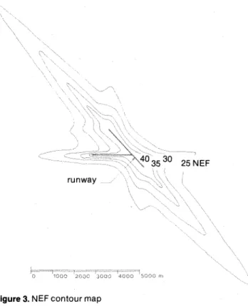
pure tones and duration. A summation is made of the noise (in EPNdB) from all aircraft types on all runways in calculating NEF values. The NEF system is used primarily to develop noise contours for areas around airports, although it can be used to provide a noise exposure value for one particular location. Figure 3 illustrates an NEF contour map for a Canadian airport of medium size. It is impor-tant to note that NEF values increase in a logarithmic manner. Thus, an increase of 10 NEF units has the effect of making the noise seem twice as loud.
3530 25 NEF runway
2000
Figure 3. NEF contour map
5.
NEF contoursTransport Canada and the Department of National Defence have provided Noise Exposure Forecast contours for major airports in Canada. These con-tours are based upon the most up-to-date informa-tion available and, where possible, on expected future conditions.
1. General
The National Research Council has analyzed many studies which have related human annoyance, com-plaint and speech interference to various noise ratings. Based on these studies the Council has related Noise Exposure Forecast values to an acceptable residential environment.
2. Community reaction
Sociological surveys (see Bibliography No. 22) have indicated that adverse community reaction may start at about 25 NEF. Above 30 NEF, com-plaints become increasingly vigorous and may be expected to take the form of concerted group action. Above 40 NEF, legal action may be expected.
The pattern of likely community reaction has been detailed by Transport Canada (see Biblio-graphy No.2) as follows:
Response Area 40 35 NEF 30 Figure 4. 3. NEF limits
Community Response Prediction'
Repeated and vigorous individual complaints are likely. Concerted group and legal action might be expected.
Individual complaints may be vigorous. Possible group action and appeals to authorities.
Sporadic to repeated individual complaints. Group action is possible.
Sporadic complaints may occur. Noise may interfere occasionally with certain activities of the resident.
Authorities must therefore expect complaints where outdoor NEF values exceed 25. Some people, how-ever, are prepared to live where noise exposure is above this value, particularly if their dwelling pro-vides an acceptable indoor noise environment. While it is theoretically possible to provide suffi-cient insulation to achieve an acceptable indoor noise environment in an area of very high outdoor noise, there is a level above which aircraft noise seriously affects living conditions no matter how much sound insulation has been applied to the actual dwelling unit.
Based particularly upon an analysis of available information with respect to scales of annoyance, complaint and the proposals and requirements of other authorities, the National Research Council considers that, with adequate sound insulation, residential development could be appropriate up to the 35 NEF level. Above this the annoyance caused by aircraft noise so seriously affects the environ-ment that residential developenviron-ment should not be encouraged. This upper level will remain under constant review.
Normal construction in new residential buildings should provide an acceptable indoor noise environ-ment up to the 25 NEF level. The evidence suggests that a broad threshold exists at the 25 N EF level above which there is an ever-increasing likelihood that normal construction will be unable to provide adequate insulation against aircraft noise. The National Research Council advises that the methods suggested in this publication for determining ade-quate sound insulation should be applied at the 25 NEF level and above. Transport Canada has advised the Corporation, however, that the accuracy of the NEF contours decreases with distance from the runway. While the 30 NEF contour is considered acceptable, the 25 NEF contour, because of devia-tions by aircraft from straight flight paths, cannot be accurately delineated. COllsequently, although this contour is provided by Transport Canada and is indicated on published contour maps, it is only used to indicate in general terms where normal construction may no longer be able to provide adequate sound insulation against aircraft noise.
4. Identification of zones
The Corporation, by reference to the appropriate Transport Canada NEF contours, has identified the following zones adjacent to airports:
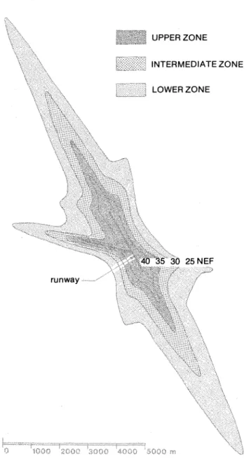
a) an upper zone - where NEF values are greater than 35.
b) an intermediate zone - where NEF values are between 30 and 35 inclusive.
c) a lower zone - where NEF values are between 25 and 30.
• It should be noted that the above community response pre-dictions are generalizations based upon experience resulting from the evolutionary development of various noise exposure u nits used by other countries.
1. Where specific Noise Exposure Forecasts are available
For all airports for which Noise Exposure Forecast contours have been made available by Transport Canada or the Department of National Defence, the Corporation has prepared NEF contour maps and considers the following application appropriate:
UPPER ZONE
INTERMEDIATE ZONE
LOWER ZONE
runway
Figure 5. Noise zones where NEF contours are available
a) the upper zone is unsuitable for housing b) the intermediate zone is unsuitable for housing
unless adequate sound insulation is provided, and
c) in the lower zone, the provision of adequate sound insulation is recommended. The upper third of this zone is unsuitable for housing, i.e. between 28 and 30 NEF, when the sound insula-tion proposed is substantially below that con-sidered to be adequate.
For specific airports, these maps may be obtained at the CMHC office in whose area the airport is located.
2. Where specific Noise Exposure Forecasts are not available
Specific forecasts are not available for all airports and the lack of aircraft movement data may prevent their preparation.
For CIVIL airports Transport Canada has prepared a series of general aviation contours. These con-tours are applied at such airports in accordance with the best advice available as coordinated by Transport Canada. The general aviation contours have the same technical base as the specific fore-casts and should be used in the same way as the specific forecasts detailed in Section D.1.
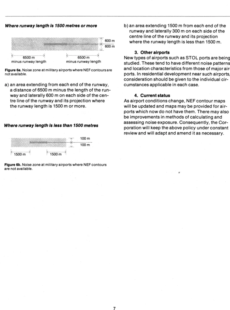
For MILITARY airports the Department of National Defence considers the general aviation contours might underrate the noise generated by military operations. For these cases an appropriate alterna-tive is related to the capability of the airport to handle jet aircraft and consequently is based on the length of the runway. Residential development should not be considered within an area related to the runway length as shown below:
Where runway length Is 1500 metres or more
VUVPᄋュMMᄋᄋᄋMMセ@ ォMMMMMセMセMMᄋセMセNZ[ェ@
6500 m •
minus runway length minus runway length Figure 6a. Noise zone at military airports where NEF contours are not available.
a) an area extending from each end of the runway, a distance of 6500 m minus the length of the run-way and laterally 600 m on each side of the cen-tre line of the runway and its projection where the runway length is 1500 m or more.
Where runway length Is less than 1500 metres
Figure 6b. Noise zone at military airports where NEF contours are not available.
b) an area extending 1500 m from each end of the runway and laterally 300 m on each side of the centre line of the runway and its projection where the runway length is less than 1500 m.
3. Other airports
New types of airports such as STOL ports are being studied. These tend to have different noise patterns and location characteristics from those of major air-ports. In residential development near such airports, consideration should be given to the individual cir-cumstances applicable in each case.
4. Current status
As airport conditions change, NEF contour maps will be updated and maps may be provided for air-ports which now do not have them. There may also be improvements in methods of calculating and assessing noise exposure. Consequently, the Cor-poration will keep the above policy under constant review and will adapt and amend it as necessary.
Section E
Adequate sound insulation
1. General
Where noise exposure values are between 25 and 35 NEF inclusive, adequate sound insulation is recommended in new dwellings. To achieve this, the building envelope, consisting of the roof and the exterior walls, doors and windows (referred to as the building components), must be capable of reducing the outdoor noise to an acceptable indoor level. The National Research Council has developed the following method which, given the NEF for the location in question, determines the appropriate building components which will provide adequate sound insulation.
The appropriate building components for any room are selected on the basis of the Acoustic Insulation Factor (AIF). This factor, which takes account of several variables including the number of components forming the envelope of the room, provides the link between the NEF and those com-ponents which will give adequate sound insulation.
Transport Canada and the Department of National Defence provide contours at different intervals and the intermediate contours are not evenly spaced because of the logarithmic nature of the contour calculation. An appropriate method of accurately locating any of the missing contours is to determine the distance between, for example, the 25 and 30 NEF contours and if this is 8, the 29 contour will be at 0.158 from the 30, the 28 at 0.338, the 27 at 0.528 and the 26 at 0.748. The contours between 30 and 35 can be located in the same way.
2. Method
The appropriate building components for any room in a dwelling are selected as follows:
a) determine by reference to the Corporation's NEF contour mapforthe airport concerned the NEFfor the building location. If the location falls between two NEF values the higher value should be used. b) determine whether the required AIF is for the
components of a bedroom or other room.
c) determine the number of components which make up the exterior envelope ofthe room from windows, walls, ceiling-roofs and doors. It should be noted: (i) where the windows and exterior doors do not form part of the exterior envelope of a room (for example the front door and small adjacent window shown in Figure 12) they must be treated and included as a component of all rooms which have an opening or doorway opposite or adjacent to them.
(ii) since the AIF is related to the total area of each type of component, the number of individual units of each type does not affect the deter-mination of AIF. For example, 6 individual windows in a room are counted as one com-ponent and their total area is used in the calculation of AIF.
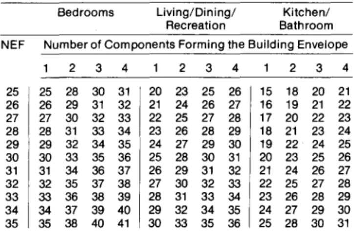
d) determine the Acoustic Insulation Factorfrom the following Tables:
Table 1: Required Acoustic Insulation Factor
Bedrooms Living/Dining/ Kitchen/ Recreation Bathroom NEF Number of Components Forming the Building Envelope
2 3 4 2 3 4 2 3 4 25 25 28 30 31 20 23 25 26 15 18 20 21 26 26 29 31 32 21 24 26 27 16 19 21 22 27 27 30 32 33 22 25 27 28 17 20 22 23 28 28 31 33 34 23 26 28 29 18 21 23 24 29 29 32 34 35 24 27 29 30 19 22 24 25 30 30 33 35 36 25 28 30 31 20 23 25 26 31 31 34 36 37 26 29 31 32 21 24 26 27 32 32 35 37 38 27 30 32 33 22 25 27 28 33 33 36 38 39 28 31 33 34 23 26 28 29 34 34 37 39 40 29 32 34 35 24 27 29 30 35 35 38 40 41 30 33 35 36 25 28 30 31
e) select the appropriate types of window, exterior wall, ceiling-roof and exterior door respectively from Tables A to 0, using the AIF obtained. Where the calculated AIF does not correspond directly to an AIF value given in the table, the next higher AIF value should be used. All the appropriate components so indicated are the minimum required to provide the degree of sound insulation recommended.
Table A - relates various types of window to AIF. Use of the table requires a calculation of the percentage of the total window area affecting a room to the total floor area of that room. Table B - relates various types of exterior wall construction to AIF. Use of the table requires a calculation of the percentage of total exterior wall area (less windows and doors) to total floor area. Table C - relates various ceiling-roof combina-tions to AIF.
Table 0 - relates various types of exterior door to AIF. Use of the table requires a calculation of the percentage of the total door area affecting a room to the total floor area of that room.
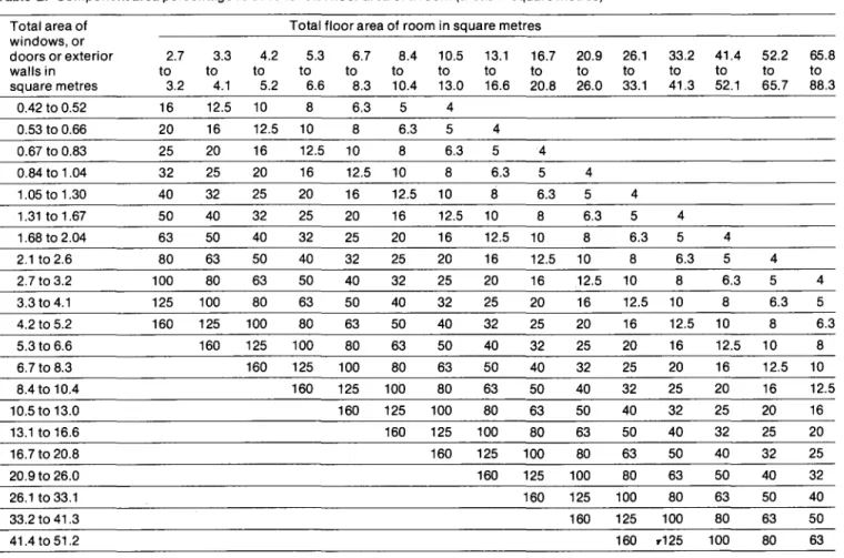
Table E - relates floor area to component area. Use of the table gives the percentages required in Tables A, Band D.
f) if a component is chosen whose AIF exceeds the required value by 10 or more, that component shall not be included in the number of elements when determining the AIF required for the other components of the room envelope.
Where a window or exterior door type has been determined in relation to more than one room, it shall comply with the highest insulation standard so, calculated. The Tables A to 0 have been compiled by the National Research Council from laboratory tests on various components. They may be revised from time to time as methods and standards of construction change and as the results of a series of field tests become available and are evaluated.
3. Associated ventilation needs
The AIF values in the tables apply to closed, fully weatherstripped doors and windows. Because the noise insulation criteria cannot be met by conven-tional windows when they are opened to provide ventilation, alternative means of ventilation are necessary. (See Appendix C.)
4. Alternative procedures
Where a proponent wishes to give more detailed consideration to the problem of noise and the subject of sound insulation, he is advised to consult a person suitably qualified in acoustics.
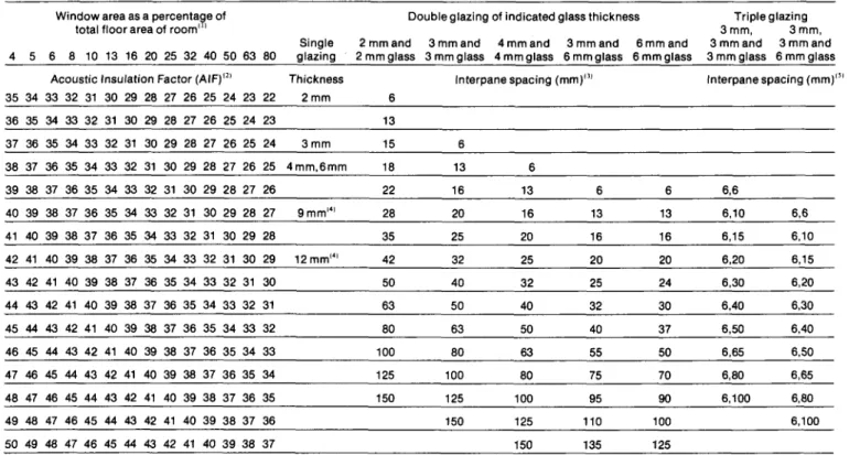
Table A: Acoustic Insulation Factor for various types of window
Window area as a ー・イ」・ョエ。セ・@ of Double glazing of indicated glass thickness total floor area of room' ,
Single 2 mmand 3mmand 4mmand 3 mmand 4 5 6 8 10 13 16 20 25 32 40 50 63 80 glazing 2 mmglass 3mmglass 4mmglass 6mmglass
Acoustic Insulation Factor (AIF)'2J Thickness Interpane spacing (mm)'lJ 35 34 33 32 31 30 29 28 27 26 25 24 23 22 2mm 6 36 35 34 33 32 31 30 29 28 27 26 25 24 23 13 37 36 35 34 33 32 31 30 29 28 27 26 25 24 3mm 15 6 38 37 36 35 34 33 32 31 30 29 28 27 26 25 4mm,6mm 18 13 6 39 38 37 36 35 34 33 32 31 30 29 28 27 26 22 16 13 6 40 39 38 37 36 35 34 33 32 31 30 29 28 27 9mm'4I 28 20 16 13 41 40 39 38 37 36 35 34 33 32 31 30 29 28 35 25 20 16 42 41 40 39 38 37 36 35 34 33 32 31 30 29 12mm'4' 42 32 25 20 43 42 41 40 39 38 37 36 35 34 33 32 31 30 50 40 32 25 44 43 42 41 40 39 38 37 36 35 34 33 32 31 63 50 40 32 45 44 43 42 41 40 39 38 37 36 35 34 33 32 80 63 50 40 46 45 44 43 42 41 40 39 38 37 36 35 34 33 100 80 63 55 47 46 45 44 43 42 41 40 39 38 37 36 35 34 125 100 80 75 48 47 46 45 44 43 42 41 40 39 38 37 36 35 150 125 100 95 49 48 47 46 45 44 43 42 41 40 39 38 37 36 150 125 110 50 49 48 47 46 45 44 43 42 41 40 39 38 37 150 135
Source: National Research Council, Division of Building Research, June 1980. Explanatory notes: 6mm and 6mmglass 6 13 16 20 24 30 37 50 70 90 100 125 Triple glazing 3mm, 3mm, 3 mm and 3 mm and 3 mm glass 6 mm glass Interpane spacing (mm)'" 6,6 6,10 6,6 6,15 6,10 6,20 6,15 6,30 6,20 6.40 6,30 6,50 6,40 6,65 6,50 6,80 6,65 6,100 6,80 6,100
(1) Where the calculated percentage window area is not presented on a column heading, the nearest percentage column in the table values should be used.
(2) AIF data listed in the table are for well-fitted weatherstripped units that can be opened. The AIF values apply only when the windows are closed. For windows fixed and sealed to the frame, add three to the AIF given in the table.
(3) If the interpane spacing or glass thickness for a specific double-glazed window is not listed in the table, the nearest listed values should be used.
(4) The AIF ratings for9 mm and 12 mm glass are for laminated glass only; for solid glass subtracttwofrom the AIFvalues listed in the table. (5) If the interpane spacings for a specific triple-glazed window are not listed in the table, use the listed case whose combined spacings are
nearest the actual combined spacing.
(6) The AIF data listed in the table are for typical windows, but details of glass mounting, window seals, etc. may result in slightly different performance for some manufacturers' products. If laboratory sound transmission loss data (conforming to ASTM test method E-90) are available, these should be used to calculate the AIF.
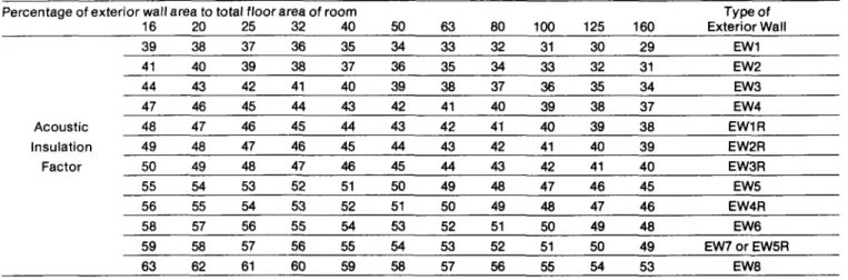
Table B: Acoustic Insulation Factor for various types of exterior wall
Percentage of exterior wall area to total floor area of room
16 20 25 32 40 50 63 80 39 38 37 36 35 34 33 32 41 40 39 38 37 36 35 34 44 43 42 41 40 39 38 37 47 46 45 44 43 42 41 40 Acoustic 48 47 46 45 44 43 42 41 Insulation 49 48 47 46 45 44 43 42 Factor 50 49 48 47 46 45 44 43 55 54 53 52 51 50 49 48 56 55 54 53 52 51 50 49 58 57 56 55 54 53 52 51 59 58 57 56 55 54 53 52 63 62 61 60 59 58 57 56
Source: National Research Council, Division of Building Research, December 1980. Explanatory notes: Type of 100 125 160 Exterior Wall 31 30 29 EW1 33 32 31 EW2 36 35 34 EW3 39 38 37 EW4 40 39 38 EW1R 41 40 39 EW2R 42 41 40 EW3R 47 46 45 EW5 48 47 46 EW4R 50 49 48 EW6 51 50 49 EW70rEW5R 55 54 53 EW8
1) Where the calculated percentage wall area is not presented as a column heading, the nearest percentage column in the table should be used.
2) The common structure of walls EW1 to EW5 is composed of 12.7 mm gypsum board, vapour barrier, and 38 x 89 mm studs with 50 mm (or thicker) mineral wool or glass fibre batts in the inter-stud cavities.
3) EW1 denotes exterior wall as in Note 2), plus sheathing, plus wood siding or metal siding and fibre backer board.
EW2 denotes exterior wall as in Note 2), plus rigid insulation (25-50 mm), and wood siding or metal siding and fibre backer board. EW3 denotes simulated mansard with structure as in Note 2), plus sheathing, 38 x 89 mm framing, sheathing, and asphalt roofing material.
EW4 denotes exterior wall as in Note 2), plus sheathing and 20 mm stucco.
EW5 denotes exterior wall as in Note 2), plus sheathing, 25 mm air space, 100 mm brick veneer.
EW6 denotes exterior wall composed of 12.7 mm gypsum board, rigid insulation (25-50 mm), 100 mm back-up block, 100 mm face brick.
EW7 denotes exterior wall composed of 12.7 mm gypsum board, rigid insulation (25-50 mm), 140 mm back-up block, 100 mm face
brick. or
EW8 denotes exterior wall composed of 12.7 mm gypsum board, rigid insulation (25-50 mm), 200 mm concrete. 4) R signifies the mounting of the interior gypsum board on resilient clips.
5) An exterior wall conforming to rainscreen design principles and composed of 12.7 mm gypsum board, 100 mm concrete block, rigid insulation (25-50 mm), 25 mm air space, and 100 mm brick veneer has the same AIF as EW6.
6) An exterior wall described in EW1 with the addition of rigid insulation (25-50 mm) between the sheathing and the external finish has the same AIF as EW2.
Table C: Acoustic Insulation Factor for various ceiling-roof combinations
Acoustic Type of
Insulation Factor Ceiling-Roof
41 C1 44 C1R or
cm
47 C2orC10R 49 C3 50 C20 52 C20RSource: National Research Council, Division of Building Research, December 1980.
Explanatory notes:
1) C1 denotes 12.7 mm gypsum board, 75 mm (or thicker) insulation batts, flat roof joist and beam construction, built-up roofing.
C2 denotes 12.7 mm gypsum board, 75 mm (or thicker) insulation batts, typical wood roof truss with ventilated attic, sheathing and asphalt roofing.
C3 denotes paint finish, 150 mrn concrete slab, 50 mm rigid insulation, built-up roofing.
Table D: Acoustic Insulation Factor for various types of exterior doors
Percentage of total door area to total floor area of room
4 5 6.3 8 10 30 29 28 27 26 34 33 32 31 30 36 35 34 33 32 37 36 35 34 33 Acoustic 38 37 36 35 34 Insulation 41 40 39 38 37 Factor 43 42 41 40 39 44 43 42 41 40 45 44 43 42 41 48 47 46 45 44 50 49 48 47 46
2) 0 signifies the addition of a second layer of 12.7 mm gypsum board.
R signifies mounting the gypsum board on wood strapping or resilient clips.
DR signifies the addition of a second layer of 12.7 mm gypsum board mounted on resilient clips.
3) Wherever possible ventilation openings to attic spaces should be in locations not directly exposed to the noise.
Exterior Type of Exterior 12.5 16 20 25 Door 25 24 23 22 01 29 28 27 26 02 31 30 29 28 03 32 31 30 29 04 33 32 31 30 050r 01-sd 36 35 34 33 02-sd 38 37 36 35 03-sd 39 38 37 36 04-sd 40 39 38 37 05-sd 43 42 41 40 03-03 45 44 43 42 05-05
Source: National Research Council, Division of Building Research, December 1980. Explanatory notes:
1) Where the calculated percentage door area is not presented as a column heading, the nearest percentage column in the table should be used.
2) All prime doors must be fully weatherstripped.
3) 01 denotes 44 mm hollow-core wood door (up to 20% of area glazed).
02 denotes 44 mm glass-fibre reinforced plastic door with foam or glass-fibre insulated core (up to 20% of area glazed). 03 denotes 35 mm in solid slab wood door.
04 denotes 44 mm steel door with foam or glass-fibre insulated core. 05 denotes 44 mm solid slab door.
Table E: Component area percentage relative to total floor area of a room (areas in square metres)
Total area of Total floor area of room in square metres windows, or doors or exterior 2.7 3.3 4.2 5.3 6.7 8.4 10.5 13.1 16.7 20.9 26.1 33.2 41.4 52.2 65.8 walls in to to to to to to to to to to to to to to to square metres 3.2 4.1 5.2 6.6 8.3 10.4 13.0 16.6 20.8 26.0 33.1 41.3 52.1 65.7 88.3 0.42 to 0.52 16 12.5 10 8 6.3 5 4 0.53 to 0.66 20 16 12.5 10 8 6.3 5 4 0.67 to 0.83 25 20 16 12.5 10 8 6.3 5 4 0.84 to 1.04 32 25 20 16 12.5 10 8 6.3 5 4 1.05 to 1.30 40 32 25 20 16 12.5 10 8 6.3 5 4 1.31t01.67 50 40 32 25 20 16 12.5 10 8 6.3 5 4 1.68 to 2.04 63 50 40 32 25 20 16 12.5 10 8 6.3 5 4 2.1 to 2.6 80 63 50 40 32 25 20 16 12.5 10 8 6.3 5 4 2.7 to 3.2 100 80 63 50 40 32 25 20 16 12.5 10 8 6.3 5 4 3.3 to 4.1 125 100 80 63 50 40 32 25 20 16 12.5 10 8 6.3 5 4.2 to 5.2 160 125 100 80 63 50 40 32 25 20 16 12.5 10 8 6.3 5.3 to 6.6 160 125 100 80 63 50 40 32 25 20 16 12.5 10 8 6.7 to 8.3 160 125 100 80 63 50 40 32 25 20 16 12.5 10 8.4 to 10.4 160 125 100 80 63 50 40 32 25 20 16 12.5 10.5 to 13.0 160 125 100 80 63 50 40 32 25 20 16 13.1 to 16.6 160 125 100 80 63 50 40 32 25 20 16.7 to 20.8 160 125 100 80 63 50 40 32 25 20.9 to 26.0 160 125 100 80 63 50 40 32 26.1t033.1 160 125 100 80 63 50 40 33.2 to 41.3 160 125 100 80 63 50 41.4t051.2 160 .. 125 100 80 63
1. General
This document has referred to the fact that sound usually enters a room by more than one route; that for upstairs rooms the paths are via windows, exterior walls and ceiling-roofs; that for downstairs, the pri-mary agents of transmission are windows, exterior walls and exterior doors, and that principal consid-eration should be given tothefollowingascontrib-uting to insulation from externally generated sound: a) the reduction of window areas to the minimum
required for adequate lighting;
b) the provision of mechanical means of ventilation to reduce the need to open windows for ventilation purposes;
c) the use of building materials with high insulation qualities. Heavy materials are usually more effective in countering sound transmission; d) the sealing of all cracks and joints between building
components. Where possible, the connections between building components should incorporate resilient fastenings. Glass should be setin resilient gaskets;
e) the incorporation of special design features where breaks occur in theexteriorenvelope. Forexample, sound baffles may be necessary in locations such as crawl space and ventilation grilles, plumbing vents, air-conditioning grilles, exhaust vents for kitchens and bathrooms, fresh-air intake grilles and chimney flues.
2.
Additional considerationsThe following considerations provide advice which may be useful to those concerned with providing residential accommodation sited near airports. They might be used, with advantage, where a particular room or building requires greater noise protection than normally expected. Reduction of noise nui-sance may be achieved by the introduction of acoustic considerations into site layout and into other aspects of dwelling design.
a) External Shielding -theeffectsofnoisegenerated from aircraft while on the runway may be reduced by introducing between the dwelling and the noise source:
Figure 7. Shielding from ground noise
(i) mounds, walls or parts of buildings not sen-sitive to excessive sound, and/or
Figure 8. Absorption of ground noise
(ii) vegetation in sufficient amounts; for example, a large tract of trees around an airport, and by
(iii) careful orientation and landscaping of build-ing groups to avoid the reflection of sound waves from facade to facade.
b) Building Layout and Orientation - within a dwelling it is possible to reduce noise levels in those rooms where noise can least be tolerated (e.g. bedrooms) by shielding them with other rooms where higher noise levels are acceptable.
Figure 9.
Thus, where flyover noise is the problem, bedrooms COUld, with advantage, be located below other rooms.
Figure 10.
Where ground nOiseistheproblem, bedrooms could be located on the side of the dwelling furthestfrom the noise source.
c) Interior Decoration -the noise level in the interior of a dwelling can be reduced by the useofmaterials with sound-absorbent surfaces, such as acoustic ceilings, heavy curtain fabrics and floor carpeting. Interior doors should bekeptclosedandautomatic closers installed.
Appendix A
Calculating Acoustic Insulation Factor from laboratory data
One major problem associated with the use of AIF ratings is the need to rate components such as doors or windows produced by various manufacturers. Tables A, B, C, and D list AIF ratings for a broad range of components, but obviously do not include all possible constructions. Also, some manufac-turers' windows or doors may provide more acoustical insulation than "typical" components because of special design features such as unusually good weatherstripping.
If such products have been tested in a laboratory in accordance with ASTM method E90 for Measure-ment of Sound Transmission Loss, the test results can be used to calculate the AIF. A detailed proce-dure for calculating the AI F and method for estimat-ing the AIF from a laboratory Sound Transmission Class (STC) are presented below.
Detailed Calculation Procedure
The difference between the outdoor Noise Exposure Forecast (NEF) and the resulting indoor NEF
depends on both the transmission loss characteris-tic of the component and the spectral content of the noise source.
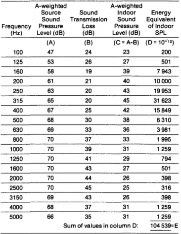
The source spectrum used for AIF calculations is given in Table A 1; it is normalized to approximately 80 dBA to provide a convenient range of values for the calculation. By subtracting the Sound Trans-mission Loss values from the A-weighted source sound levels, the corresponding A-weighted indoor sound levels in each V3-octave band are obtained.
Combining these %-octave band levels yields the overall A-weighted sound level that would be mea-sured in a room if only that component were trans-mitting sound, and the component area were equal to the acoustical absorption (typically 80 per cent of room floor area). This level is subtracted from 77 dBA (a value obtained by combining the %-octave band source levels and correcting to allow for dif-ferences between the source sound field at an exterior facade and that in laboratory test chambers, as discussed in the reference). This gives the AIF for component area equal to 80 per cent of room floor area. For other percentages (P) of component area relative to floor area, the AI F may be calculated by subtracting 10 log (P/80) from the AIF value for 80 per cent. The calculated values should be rounded to the nearest integer.
The calculation procedure is illustrated by the example given in the worksheet in Fig. A 1.
Estimating the Acoustic Insulation Factor from
STC
In some cases a manufacturer or his agent may know the STC of a product, but be unable to provide the V3-octave band Sound Transmission Loss data.
This should not occur, because in order to deter-mine the STC, one must first obtain the Sound Transmission Loss data for the %-octaves from 125 Hz to 4000 Hz. Laboratory reports of STC determina-tions consistent with the ASTM standard E413 should include this information.
If detailed sound transmission loss data are not available, the AIF can be estimated from the STC value, using Table A2 for doors and windows, or Table A3 for walls. Because the estimate tends to give slightly lower values for the AI F than are obtained from the detailed calculation, it is usually to a manufacturer's advantage to use the detailed calculation procedure.
Reference: Acoustic Insulation Factor: A Rating for the Insulation of Buildings Against Outdoor Noise, National Research Council, Division of Building Research. Building Research Note 148. Revised July 1980.
Table A1: Standard source spectrum for calculating Acoustic Insulation Factor (AIF)
A-weighted Frequency Source Sound Source Sound
(Hz) Pressure Level Pressure Level
100 66.1 47 125 69.1 53 160 71.4 58 200 71.9 61 250 71.6 63 315 71.6 65 400 71.8 67 500 71.2 68 630 70.9 69 800 70.8 70 1000 70.0 70 1250 69.4 70 1600 69.0 70 2000 68.8 70 2500 68.7 70 3150 67.8 69 4000 67.0 68 5000 65.5 66
Note: Values in the second and third columns of this table are Va-octave band sound pressure levels expressed in dB.
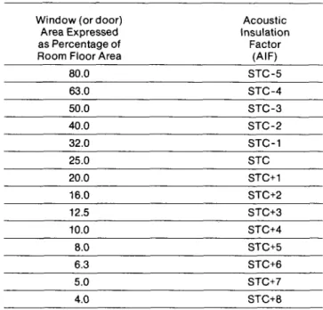
Table A2: Approximate conversion from STC to AIF for windows
and doors
Window (or door) Acoustic Area Expressed Insulation as Percentage of Factor Room Floor Area (AIF)
80.0 STC-5 63.0 STC-4 50.0 STC-3 40.0 STC-2 32.0 STC-1 25.0 STC 20.0 STC+1 16.0 STC+2 12.5 STC+3 10.0 STC+4 8.0 STC+5 6.3 STC+6 5.0 STC+7 4.0 STC+8
Note: For area percentages not listed in the table, use the nearest listed value.
Examples: For a window whose area = 20% of the room floor area and STC = 32, the AIF is 32 + 1 = 33.
For a window whose area = 60% of the room floor area and STC = 29, the AIF j.s 29 - 4 = 25.
Table A3: Approximate conversion from STC to AIF for exterior walls and ceiling-roof systems.
Exterior Wall Acoustic
Area Expressed Insulation
as Percentage of Factor
Room Floor Area (AIF)
200.0 STC-1O 160.0 STC-9 125.0 STC-8 100.0 STC-7 80.0 STC-6 63.0 STC-5 50.0 STC-4 40.0 STC-3 32.0 STC-2 25.0 STC-1 20.0 STC 16.0 STC+1 12.5 STC+2 10.0 STC+3 8.0 STC+4
Note: For area percentages not listed in the table, use the nearest listed value.
Example: For a wall whose area = 120% of room floor area and STC = 48, the AIF is 48 - 8 = 40.
Note: For ceiling-roof systems, AIF = STC -7.
Figure A1: Worksheet for Calculating AIF from Transmission Loss
Data
A-weighted A-weighted
Source Sound Indoor Energy Sound Transmission Sound Equivalent Frequency Pressure Loss Pressure of Indoor
(Hz) Level (dB) (dB) Level (dB) SPL (A) (B) (C= A-B) (D = 10'/10) 100 47 24 23 200 125 53 26 27 501 160 58 19 39 7943 200 61 21 40 10000 250 63 20 43 19953 315 65 20 45 31623 400 67 25 42 15849 500 68 30 38 6310 630 69 33 36 3981 800 70 37 33 1995 1000 70 39 31 1259 1250 70 41 29 794 1600 70 43 27 501 2000 70 44 26 398 2500 70 45 25 316 3150 69 43 26 398 4000 68 37 31 1259 5000 66 35 31 1259
Sum of values in column D: 104539=E Calculated indoor A-weighted sound level: 10 IOg10 (E) = 50.2 = F AIF (component area = 80% of floor area): (77 - F) = 26.8 = G
Component Area Acoustic
as a Percentage of Insulation Room Floor Area Factor (AIF)
6.3 (G+11)=38 8.0 (G+10)=37 10.0 (G+ 9) =36 12.5 (G+ 8) = 35 16.0 (G+ 7) =34 20.0 (G+ 6) = 33 25.0 (G+ 5) = 32 32.0 (G+ 4) = 31 40.0 (G+ 3) =30 50.0 (G+ 2) = 29 63.0 (G+ 1) = 28 80.0 (G ) = 27
Appendix B
Derivation of Table 1
The Acoustic Insulation Factors set out in Table 1 are obtained by the following steps:
1. Take the numerical value of the NEF contour for the location under consideration.
2. To derive the sound insulation requirementforthe exterior building envelope of a particular room, adjust the outdoor NEF value as follows: For bedrooms add 0
For living/dining/recreation rooms deduct 5 For kitchen/bath rooms and other rooms ded uct 10 These values of NEF + 0, NEF - 5 and NEF -10 for the sound insulation required in the building envelope have been recommended by the National Research Council based particularly on a review of studies related to thresholds of annoyance and speech interference. They are related to accept-able indoor noise levels equivalent to NEF = 0 units for bedrooms, NEF = + 5 for living, dining and recreation rooms and NEF = + 10 for kitchens, bathrooms and other rooms. The difference of 5 un its between each ofthe differenttypes of accom-modation allows for the desirability of reducing the noise level relative to the particular use and of having the least noise in sleeping accommodation. 3. To arrive at the sound insulation required for the
individual components of the room envelope: make no adjustment to the above figures when there is 1 component, add 3 wherethereare2com-ponents, add 5 where there are 3 com wherethereare2com-ponents, and add 6 where there are 4 components.
These adjustments are made because, as more components are added to the exterior room enve-lope, the effective insulation of all components is reduced.
The final figure istheAcoustic Insulation Factor.
To summarize: Number of components forming the Room Envelope Bedrooms 1 component NEF 2 components NEF+3 3 components NEF+5 4 components NEF+6 AIF for Living/Dining/ Kitchens/ Recreation Bathrooms NEF-5 = -5 NEF -10 = -10 NEF -5 + 3 =-2 NEF-10+3=- 7 NEF-5+5= 0 NEF-10+5=- 5 NEF -5 + 6 = +1 NEF-10+6=- 4 l'
No matter what components are selected, the difference between the outdoor and indoor NEF is unlikely to exceed 20 dB if the windows are opened to provide ventilation. For residential rooms with a window opening of 0.3 m2 (the minimum
require-ment of the Canadian Residential Standards), the noise reduction is typically between 10 and 20 dB, depending on the size and furnishing of the room. Obviously the noise reduction can be increased by partially closing the windows, but for sites where the NEF is greater than 25, the indoor noise limits of Table C.1 cannot be satisfied if the windows are opened appreciably. Although this does not pose a problem during the winter, the windows can only be kept closed during the summer if an alternative means of ventilation is provided. For most heavily populated areas in Canada a mechanical ventilation system would have to include air conditioning to provide reasonable comfort in the warmer months.
Insulating residential buildings against aircraft noise necessitates "alternative means of ventilation" for sites where the NEF is greater than or equal to 30. For sites where the NEF is between 25 and 30, an alternative means of ventilation is recommended, but not mandatory. In practice the phrase "alterna-tive means of ventilation" is normally interpreted as a requirement for air conditioning.
Where it is not essential, developers may not wish to include air conditioning because of the resulting increase in the selling price or rental rate. The use of a forced-air heating system with ducting appro-priate for air conditioning should be encouraged in such cases. This will permit the eventual occupants to readily add air conditioning at a later date if they find the noise admitted by opening the windows for ventilation to be unacceptable. Even without air conditioning, such a system can partially fulfil the ventilation requirements if provisions are made to exhaust the cold air return ducts to outside and suck fresh airfrom outside into the cold air return plenum. To minimize noise entering through the air-handling system, the inlet and outlet ducts should be designed to provide some noise attenua-tion. Lining the ducts with suitable acoustical absorption material and including at least one 900 bend in the lined segments is one example of such treatment.
Table C.1: Recommended Indoor Noise Exposure Criteria
Use of Space Recommended Maximum Indoor NEF Bedrooms Living, Dining, Recreation Kitchen, Bathroom
Reference: National Research Council, Division Building Research. Building Research Note 148 (Revised June 1980).
o
5 10
Minimum System for Mechanical Ventilation for Forced Warm
Air,
Fuel-Fired Systems The following system may be considered to be the minimum acceptable to provide mechanical ventilation.Components
This system will comprise:
1. A fresh air inlet connecting the exterior to the cold air return plenum. (Minimum 150 mm diameter duct properly insulated, with regulating damper.) 2. A roof-ceiling exhaust fan or suitable alternative
installation complete with damper and noise baffles. (Capacity for % air change per hour.) It is recommended that the exhaust be located on the side of the house which is least exposed to sound. 3. A furnace with a two-speed circulating fan. 4. A manual damper located between the fresh air
inlet and any cold air inlet in the main cold air return duct.
Operation
Winter - Fresh air will be drawn in through fresh air inlet to make up air lost through the chimney flue and the exhaust fan. This air is heated and distributed by the heating system. The damper on the cold air return is open. The two-speed fan on the furnace will ensure continuous operation. This should provide 1 air change per hour.
Summer - The damper Oil the cold ai r return is closed. The furnace fan will draw air through the fresh air inlet and circulate through the heating system. Stale air will escape through the chimney flue and the exhaust fan. For a standard furnace with a circulating fan, this should provide approxi-mately five air changes per hour. It is recognized that for severe summer conditions this may not be sufficient and temporary additional ventilation by means of open windows may be necessary.
1 Exhaust vent
2 Sound alteration box
3 Insulated duct laid to slight fall to exterior
4. Flexible connection
ft/
5
6 _
1 Fresh air duct
2 Regulating damper 3 150 mm dia. insulated duct 4 Manual damper Summer-almost closed Winter-open
Figure 11. Mechanical ventilation
5 Exhaust fan
6 Gasket
7 Silencer
8 Ceiling grille
5 Cold air return
6 Circulating fan driven by 2-speed motor
Appendix 0
Adjustments to the basic calculation of required AIF
It is recognized that other architectural considera-tions may lead to designs having some components with AIF ratings that exceed the requirements in Table 1. In such cases it is reasonable to slightly relax the AI F requirements for the other components of the building envelope. Where the AIF of any component exceeds the required AIF by 10 or more, the calculation should be repeated for the other components with the "total number of components" reduced by one. This reduction in the number of components lowers the required AIF for the others. No adjustment is made if a component's AIF exceeds the requirement by less than 10.
The most important design consideration is to ensure that the total noise reduction by the com-ponents is consistent with the desired difference between the outdoor and indoor noise exposures. The required AIF values in Table 1 indicate the average acoustical insulation required for the number of components in the exterior envelope of the room. Deviations from this average AIF are acceptable, provided the decrease in noise reduction by the weaker components is offset by a corre-sponding increase in noise reduction by the others. The necessary adjustments can be calculated by simply using Table D.1, as illustrated in the follow-ing example. (Note that the "average" AIF is not a simple arithmetic average of the component AIF values.)
Example
Consider the design for a bedroom in a house at a site where the NEF = 32. The room has three com-ponents in its exterior envelope: ceiling-roof, exterior wall and windows. From Table 1 the aver-age required AIF is 37. If other architectural con-siderations led to choosing a ceiling-roof with an AIF =
50
and an exterior wall with an AIF = 43, what AIF is required for the windows?Using Table 01, the ceiling-roof, with an AIF more than
10
pOints above the required average value, is rated at - 30 in the three component column, i.e., it would transmit 30 per cent less than its share of the total transmitted sound. Similarly the selected wall, which has an AIF six pOints above the required average value, transmits 25 per cent less than its share. The total sound transmission by these two components is thus55
per cent less than their share. Therefore the window component may be allowed to transmit up to 55 per cent more than its share of the total, and from Table 01 its AIF rat-ing can be 4 below the specified average value, i.e. 37 -4 = 33.If the same situation was evaluated using the procedure established in Section E, the windows would be required to have AIF = 35 (the value from Table 1 for a bedroom with two components; the ceiling-roof is not included).
23
Table D1: Adjustment to AIF Component AI F
minus Average Total No. of Components
Required AIF 2 3 4 10 or more -45 -30 -22 9 -44 -29 -22 8 -42 -28 -21 7 -40 -27 -20 6 -37 -25 -19 5 -34 -23 -17 Percentage 4 -30 -20 -15 change in 3 -25 -17 -12 total trans-2 -18 -12 - 9 mitted sound 1 -10 - 7 - 5 0 0 0 0 -1 13 9 6 -2 29 20 15 -3 50 33 25 -4 76 50 38 -5 108 72 54
WorksheetforTable D1: (Using Example) Outdoor Noise Exposure Forecast.. 32
Number of Components ... 3 AveragerequiredAIF 37 Type of Room ... Bedroom (from Table 1)
-..
Component AIF AIF MinusAverage Required AIF Transmitted Sound Increase in Ceiling-Roof 50 13 (more than 10) -30%
Exterior Wall 43 6 -25%
Windows 33 -4 50%
Doors -%
Overall increase in total transmitted sound
=
-
5 %Reference: National Research Council Division of Building Research Building Research Note 148 (Revised June 1980).
Worked examples are given to illustrate the method of determining the building components for ade-quate sound insulation of dwellings. The examples are of a bungalow, a two-storey house, a row house and an apartment all located at the 35 NEF level. The examples are given for guidance purposes only and the opportunity is taken to highlight features which require careful consideration in making the calculation.
It will be noted that there are various alternatives open to builders and architects which will fulfil the sound insulation requirements. Alternatives have not been given in the examples which follow. Designing rooms to reduce the number of com-ponents in the envelope and the ratio of window area to floor area may permit the use of components with lighter materials. Careful design may avoid potential cost increases and facilitate standardiza-tion of components. However, it should be noted that components with higher Acoustic Insulation Factors are not necessarily more costly.
In practice many of the components used in typical apartment construction have to take account of the need for greater fire protection, thermal insulation, wind resistance, etc., and as a result they may be found to have adequate acoustic insulation from aircraft noise.
Example 1 A 3-bedroom bungalow
To determine the appropriate building components for this dwelling it is necessary to undertake calcu-lations for the dining room, the living room, the kitchen, the three bedrooms, the bathroom and the basement. Two features of the dwelling require special consideration, the living room and dining room form one large room and the rear exterior door is adjacent to the doorways of both the kitchen and the dining room.
bedroom 1
FLOOR PLAN
FRONT
REAR
Figure 12. A 3-bedroom bungalow
rear entry front entry LEFT RIGHT
25
Building location 35 NEFAcoustic Insulation Factors Dining-living room
The calculation is made for the entire area as one room. The components are:
First component: windows, including the window in the front closet.
Second component: exterior walls, measured from the back of the front closet to the rear door. Third component: the ceiling-roof.
Fourth component: the front and rear exterior doors. Total number of components::: 4.
From Table 1: AIF::: 36. Kitchen
Components are the window, exterior wall, ceiling-roof and rear exterior door.
Total number of components::: 4. From Table 1: AIF ::: 31.
Bedrooms 1, 2 and 3
Each bedroom has three components window, exterior wall and ceiling-roof.
From Table 1: AIF::: 40. Bathroom
Three components - window, exterior wall and
ceiling-roof. r
From Table 1: AIF ::: 30. Basement
Two components - window and exterior wall. From Table 1: AIF::: 28.
Appropriate components
It is necessary at this stage to calculate the per-centages of the total window area, total exterior door area and the net exposed exterior wall area. (Le. excluding window and door areas) to the total floor area for each room. These percentages are:
% Window % Exteriorwall % Exteriordoor Room area to tota I area to total area to total
floor area floor area floor area Dining-living 26 (1) 110 14 (2) Kitchen 16 72 26 Bedroom 1 15 134 Bedroom 2 13 155 Bedroom 3 22 57 Bathroom 20 77 Basement 4 27
Notes: (1) The window area includes the window in the front closet.
(2) The total door area is the area of the front and rear exterior doors.
(3) The total door area is the area of the rear exterior door only.
By reference to Tables A to D determine the appropriate components.
Summary
Dwelling: A 3-bedroom bungalow Building location: NEF 35
Dining- Bed-Kitchen room 1 No. of 4 3 Acoustic Insulation Factor 36 31 40 %Windowto floor area 26 16 15 % Exterior wall to floor area 110 72 134 % Exterior door to floor area 14 26 Bed-room 2 3 40 13 155 Appropriate components Windows (Table A) 2(63)2 3mm 2(100)2 2(80)2 Exterior walls
EW3 EW1 EW2R EW3R
C1 C1 C1 C1
Bed- Bath- Base-room 3 room ment
3 3 2
40 30 28
22 20 4
57 77 27
2(125)2 3mm 2mm EW4 EW1 EW1
Example 2 A 4-bedroom two-storey detached house
To determine the appropriate building component for this dwelling it is necessary to undertake calcu-lations for the dining room, the living room, the kitchen, the four bedrooms, the bathroom and the basement. Two features of the dwelling require special consideration: the living area and the dining area form one room and the dining room has a glazed and not a solid exterior door.
FRONT
bedroom 1
UPPER FLOOR PLAN patio entry REAR RIGHT side. entry? LOWER FLOOR PLAN living
Figure 13. A 4-bedroom two-storey detached house
Building location
35 NEF
Acoustic Insulation Factors Dining-living room
Because the exterior door in the dining room is fully glazed it is treated as a window and is included in the calculation of the percentage window area to floor area. A component is included for the front exterior door.
There are three components - window, exterior wall and exterior door.
From Table 1: AIF = 35.
27
Kitchen
The components are the window, exterior wall and exterior door (the latter consisting of both the front and side exterior doors). The total number of components = 3.
From Table 1: AIF = 30. Bedrooms 1, 2, 3 and 4
Each bedroom has three components - window, exterior wall and ceiling-roof.
From Table 1: AIF = 40.
Bathroom
There are three components - window, exterior wall and ceiling-roof.
From Table 1: AIF = 30. Basement
There are two components - window and exterior wall.
From Table 1: AIF = 28.
Appropriate components
It is necessary at this stage to calculate the per-centages of the total window area, total exterior door area and the net exposed exterior wall area (Le. excluding window and door areas) to the total floor area for each room. These percentages are:
% Window Room area to total floor area Dining-living 29 (1) Kitchen 22 Bedroom 1 20 Bedroom 2 22 Bedroom 3 21 Bedroom 4 31 Bathroom 22 Basement 4 % area to total floor area 89 100 100 87 20 % Exteriordoor area to total floor area 8 (5) 23
Notes: (1) The window area includes the fully glazed dining room exterior door and the small window adjacent to the front exterior door.
(2) The window area includes the small window adjacent to front exterior door.
(3) The window area includes the stairwell window. (4) The total exterior wall area includes the area of the
side wall as far as the stairwell.
(5) The door area is that of the front exterior door only. (6) The door area is that of the front and side exterior
doors.
By reference to Tables A to D determine the appropriate components.
Summary
Dwelling: A 4-bedroom two-storey detached house Building location: 35 NEF
Dining- Bed-
Bed-Room Kitchen room 1 room 2 Numberof 3 3 3 3 Acoustic Insulation Factor 35 30 40 40 1 % Window to floor area 29 22 20 22 % Exterior wall to floor area 89 100 100 117 % Exterior door to floor area 8 23 Appropriate components Windows (Table A) 3(50)3 3(6)3 3(100)3 3(100)3 Exterior walls
EW3 EW1 EW1R EW2R
C1 C1
Exterior doors
D1sd D1sd
Example 3 A 3-bedroom row house
To determine the appropriate building components for this dwelling it is necessary to undertake calcu-lations for the kitchen-dining room, the living room, the bathroom and the three bedrooms. No calcula-tion is required for the crawl space. The front and rear exterior doors open to a hallway; each is related for calculation purposes to the adjacent room.
Bed- Bed- Bath- Base-room 3 room 4 room ment
3 3 3 2
40 40 30 28
21 31 22 4
104 114 87 20
3(100)3 3(150)3 3(6)3 2mm EW1R EW2R EW1 EW1
C1 C1 C1
rear entry
bedroom 2 kitchen-dining_
living
UPPER FLOOR PLAN
Bui/ding location 35NEF
Acoustic Insulation Factors Living room
There are three components to this room - window, exterior wall and front exterior door.
From Table 1: AI F = 35. Dining-kitchen
There are three components to this room - window, exterior wall and rear exterior door.
From Table 1: AIF = 35. Bedrooms 1, 2 and 3
Each bedroom has three components - window, exterior wall and ceiling-roof.
From Table 1: AIF = 40. Bathroom
There are three components to this room - window, exterior wall and ceiling-roof.
From Table 1: AIF = 30. Summary
Dwelling: A 3-bedroom row house Building location: 35 NEF
Dining- Bed-kitchen room 1 Numberof 3 3 Acoustic Insulation Factor 35 35 40 %Windowto floor area 17 18 11 % Exterior wall to floor area 44 47 55 % Exterior door to floor area 11 12 Appropriate components Windows (Table A) 2(35)2 2(42)2 2(63)2 Exterior walls
EW1 EW2 EW4
C1 Exterior doors
D2sd D2sd
Appropriate components
It is necessary at this stage to calculate the per-centage of the total window area, total exterior door area and the net exposed exterior wall area (Le. excluding window and door areas) to the total floor area for each room. These percentages are:
% Window % Exteriorwall % Exteriordoor Room areatototal area to total area to total
floor area floor area floor area
Living room 17 44 11 (1) Dining-kitchen 18 47 12 (2) Bedroom 1 11 55 Bedroom 2 13 84 Bedroom 3 16 72 Bathroom 37 125
Notes: (1) The door area is the front exterior door only. (2) The door area is the rear exterior door only. By reference to Tables A to D determine the appropriate components.
Bed- Bed- Bath<-room 2 room 3 room
3 3 3
40 40 35
13 16 37
84 72 125
2(80)2 2(100)2 2(28)2
EW4 EW4 EW1
Example 4 A one-bedroom apartment To determine the appropriate building components for this dwelling it is necessary to undertake calcu-lations for the living room and the bedroom only, since the kitchen and the bathroom have no exterior components. The apartment, which is an end unit abutted by a stairwell, has windows across the full width of the bedroom. The living room has a solid door to the balcony.
dining
bedroom living
FLOOR PLAN
balco'ny .... entry
Figure 15. A one-bedroom apartment. Building location
35NEF
Acoustic Insulation Factors Living-dining room
There are three components:
First component: window.
Second component: exterior wall, above the window and door.
Third component: door to balcony. From Table 1: AIF = 35.
Bedroom
There are two components: First component: window.
Second component: exterior wall, measured from the abutting corner of the stairwell to the living room.
From Table 1: AIF = 38.
Appropriate components
It is necessary at this stage to calculate the per-centage of the total window area, total exterior door area and the net exposed exterior wall area (i.e. excluding window and door areas) to the total floor area for each room. These percentages are:
% Window % Exterior wall % Exteriordoor Room areatototal area to total area to total
floor area floor area floor area
Living-dining 25 8 8
Bedroom 40 55
By reference to Tables A to D determine the appropriate components.
Summary
Dwelling: A one-bedroom apartment Building location: 35 NEF
Room Number of Acoustic Insulation Factor %Windowto floor area % Exterior wall to floor area % Exterior door to floor area Windows (Table A) Exterior walls (Table B) Living-dining 3 35 25 8 8 Appropriate components 2(50)2 EW1 Bedroom 1 2 38 40 55 2(150)2 EW3