Children, Cybernetics,
and Programmable Turtles
by Fred Martin
Massachusetts Institute of Technology
Submitted to the Department of Mechanical Engineering in partial fulfillment of the requirements for the degree of Master of Science in Mechanical Engineering
at the
Massachusetts Institute of Technology August 1988
( Fred Martin 1988. All rights reserved.
The author hereby grants to MIT permission to reproduce and to distribute copies of this thesis document in whole or in part.
Signature of Author
-Department of Mechanical Engineering August 12, 1988
Certified by ·- ~"~'~ -
-Seymour Papert, Thesis Supervisor Professor of Media echnology
--- - _
Woodie Flowers, Thesis Reader Professor of Mechanical Engineering
Accepted by
Ain Sonin Professor of Mechanical Engineering
MASSAiiUSt,. 1TS ii'STIT'd OF TENOLOGY
SEP 06 1988
LArchives Accepted by . -~ ~-Children, Cybernetics,
and Programmable Turtles
by Fred Martin
Massachusetts Institute of Technology
Submitted to the Department of Mechanical Engineering in partial fulfillment of the requirements for the degree of Master of Science in Mechanical Engineering
at the
Massachusetts Institute of Technology August 1988
Abstract
A microworld to support investigations of cybernetics is developed, con-sisting of a miniature computer programmable in Logo, called the "Logo Brick," a:lc mobile mechanical vehicles built of LEGO plastic parts. These "Programmable Turtles" are equipped with various sensors, including touch sensors and light sensors.
A series of experiments with these materials is performed with two groups of elementary school children, aged from twelve to fifteen years. The children design behaviors for the Turtles by writing Logo programs and building materials in the Turtles' environment.
The children encounter several powerful ideas in cybernetics: feedback, multiple levels of analysis, and object/environment boundaries. Through the course of the experiments, their understanding of the Programmable Turtles deepens and becomes more flexible.
Acknowledgements
Many people contributed to the ideas presented in this thesis. In some ways I am the scribe for ideas that were developed in on-going conversations. I would like to especially thank:
· Mitch Resnick and Steve Ocko, for developing LEGO/Logo in the first place, and always having big reservoirs of great ideas.
o Brian Silverman, for being the genius behind the technology. * Allan Toft, for his support from the Land of LEGOs.
* Mario Bourgoin and Aaron Falbel, for providing helpful criticism of drafts of the writing.
* Edith Ackermann, for continuously challenging me. * Seymour Papert, for making all of this possible.
* LEGO A/S Denmark, for providing the financial backing for this work.
Fred Martin August 10, 1988
Contents
1 Introduction 7
2 Theoretical Background 12
2.1 A Short History of Cybernetics ... . . 12
2.2 Educational Initiatives ... .. 17 3 Programmable Bricks 23 3.1 Logo Bricks ... 23 3.2 Sensor Devices ... 25 3.3 Braitenberg Bricks ... 27 4 Description of Experiments 28 4.1 Format of the Experiments . ... 28
4.2 Research Methodology . ... 29
4.3 Materials Used in the Experiments . ... 30
4.3.1 Programmable Turtles ... 30
4.3.2 Programming Tools .... ... .. . 31
4.4 Description of Experiments: Hennigan Children ... . 33
4.4.1 The Baseball Game ... 34
4.4.2 The Turtle Racetrack Game ... 35
4.4.3 Two-Turtle Experiments ... 35
4.4.4 Braitenberg Experiments ... 37
4.5 Description of Experiments: Newton Children ... 37
4.5.2 Programmable Turtles.
5 Narrative of Experiments
5.1 Experiments with Hennigan Children ...
5.1.1 Introductory Work . . . . 5.1.2 Logo Brick: Motors, Touch Sensor, and Light Sensor 5.1.3 The Baseball Game Project ...
5.1.4 The Turtle Racetrack Game ... 5.1.5 Two-Turtle Experiments . 5.1.6 Braitenberg Experiments.
5.2 Experiments with Newton School Children. 5.2.1 LogoWriter Screen Robots ... 5.2.2 Programmable Turtles ... 6 Analysis of Experiments
6.1 Turtle Anthropomorphism ... 6.2 Multiple Levels of Interpretation ... 6.3 Feedback and Following the Light ...
6.4 Multi-Processing and Environment Programming.
7 Conclusion
7.1 Future Directions.
7.1.1 Sensor and Actuator Development. 7.1.2 Inter-Brick Communications . 7.1.3 Programming Metaphors. 7.2 Research Experimentation. 7.3 Pedagogy ...
A The Logo Brick
A.1 History of the Brick ... A.2 How to Use the Brick ...
38 40 40 40 41 44 ... . .46 ... . .46 ... . .48 ... . .49 ... . .49 ... . .53 57 ... . .57 ... . .59 ... . .60 62 65 65 65 66 68 70 72 74 74 76
A.2.2 Setting Up ... A.2.3 User Interface ...
A.2.4 Naming and Saving Logo Pages . A.2.5 Text Editing Functions ... A.2.6 Brick LEGO/Logo ... A.2.7 Operating the Brick ... A.2.8 Debugging.... ... A.3 Technical Specifications ...
77 77 78 79 81 82 83 85 . . . . . . . . . . . . . . . . . . . . . . . . . . . . . . . .
List of Figures
2.1 Braitenberg Vehicle No. 1 ... 19
2.2 Braitenberg Vehicles No's. 2a and 2b ... 20
2.3 Braitenberg Vehicles 2a and 2b Encountering a Light .... 20
3.1 The Logo Brick ... 24
3.2 Illustration of Light Sensor ... 26
4.1 Programmable Turtle with Logo Brick and Battery Pack .. 32
5.1 Sketch of the Baseball Game Board ... 45
5.2 Sketch of Turtle Racetrack ... 47
5.3 Trapping Obstacle ... 52
5.4 Wedge and Retreat Angle ... 53
5.5 Turtle Race Game Screen Display ... 54
Chapter 1
Introduction
This thesis is about cybernetics, the study of systems or feedback net-works of interacting elements. It's also about children's thinking as they build robots and observe them Interacting with their environment and other robots. And it is about the relevance of this work to science education.
The foundations of cybernetics were laid two thousand years ago by the inventions of the Hellenistic period. But its principles remained in obscurity until James Watt's invention of the steam engine governor in 1784. The governor had an enormous impact on the technology of the era, catalyzed the birth of the Industrial Age, and introduced the study feedback control as an engineering technique.
In the 1940's, the work of pioneer cybernetician Norbert Wiener and others showed how the feedback could be used in a variety of areas of scien-tific inquiry, such as physiology and psychology. A community of scientists developed methods and styles of inquiry of the field which came to be called cybernetics. The modern methods of dynamical systems analysis and con-temporary theories of mind such as the Society of Mind by Marvin Minsky have precursors in the work of the cyberneticians of the 1940's and 1950's.
The concepts of systems theory, such as feedback, seem very complex, but that is because they are explored in highly abstract and mathematical ways. The Swiss psychologist Jean Piaget argues that as a child's mind develops to become able to perform abstract types of thought, it passes through stages which support these forms of thought. I believe that the concepts of cyberneticians could have a corresponding pre-formal represen-tation in minds of children and novice adults.
Seymour Papert argues that many ideas of mathematics are hard to learn because the tools for their appropriation do not exist in the learner's environment. This explains why people have trouble with classroom-style mathematics; the tools used to learn mathematical ideas are abstract and make it difficult for the learner to "sink his teeth" into the material. In his book Mindstorms, Papert describes the development cf Logo, a computer programming language designed to support the "speaking" of mathematics in a way analogous to how living in France supports the speaking of French. Papert explains how the Logo language could be situated in an envi-ronment of "math-speaking" persons and other materials that support the development of an active mathematical mind. Logo would have a central role in this environment which Papert calls "Mathland." (Papert 1980)
If this need for materials of appropriation is true of mathematics, than it makes sense to explore a miniature Mathland, or microworld, that supports the techniques of cyberneticians. I will review four microworlds which make these ideas accessible to children and novices:
* animal microworlds software being developed by Roy Pea and asso-ciates (Pea et al. 1988);
* a mechanical and computer-based building system, called LEGO/Logo, developed by Papert, Ocko, and Resnick (Ocko et al. 1988).
The work des-cribed in this thesis is based around an extension to the LEGO/Logo system in which the computer, rather than being a desk-sized personal computer, is miniaturized to the size of a deck of cards. It can then be incorporated into a LEGO machine, and each machine can literally carry its own program. Very small computers encourage the design of mobile, animal-like machines, which can interact with each other in unpredictable and interesting ways.
Several sorts of sensors were created for the "artificial animals" to re-ceive data from their environment.
These materials were developed to meet three goals:
1. To build a flexible and engaging microworld that can provide children access to the powerful ideas of the cyberneticians.
2. To learn about children's intuitive ideas relating to feedback and sys-tems thinking.
3. Through experimentation, learn how to make these ideas more readily understandable to children.
When the technological materials were ready, they were used in a series of experiments with children.
The first of those who used the materials were fifth grade children at-tending the Hennigan school in Jamaica Plain, Massachusetts, the site of
a three-year-long Logo project called Project Headlight, led by Seymour Papert and his M.I.T. associates. The children had had intensive computer and Logo programming experience while part of Project Headlight.
Afterwards, experiments were done with a group of seventh and eighth grade students who were attending a private school in Newton, Massachu-setts. The experiments with the fifth grade children took place over the course of a school year (nine months), while those done with the older children took place over a six-week period. These experiments are described in Chapter 4.
Experience gained in one experiment often guided the construction of subsequent ones; the activities performed with the older children made considerable use of knowledge gained in earlier experiments. This forms a design cycle for making the system more understandable to children. The steps in this cycle are: developing a prototype system, observing children using this system, analyzing how they appropriate or have trouble appro-priating certain ideas, and then redesigning the system in order to try again.
In Chapter 5, the children's activities in each of these experiments are described. Chapter 6 contains an analysis of the children's work which brings out the following issues:
1. Development of the children's understanding of feedback, as relating to activity they have designed for their robot turtle.
2. Children's tendency to anthropomorphize the turtle into a living crea-ture, which affects the style of interaction they have with it.
4. Emergent phenomena resulting from multi-processing (multiple robot interactions) and "environment programming" (robot behavior af-fected by programming the environment).
The conclusion, in Chapter 7, suggests improvements and extensions to the materials including new sensor technology and more powerful program-ming paradigms, proposes alternate styles of research using the materials, and makes connections between the experiments and science education.
Chapter 2
Theoretical Background
2.1
A Short History of Cybernetics
The field of cybernetics began with a single idea, that of a feedback system. Using negative feedback, a system is able to regulate one or more variables by making corrections to its performance. These corrections are based on observations of its current state.
For example, you are part of a feedback system, where you act as the controller and sensor, when you adjust the temperature of your morning shower. If the water feels too cold, you make it hotter (with either more hot water or less cold). If the water feels too hot, you make it colder. You repeat this action of testing and then correcting several times before you are satisfied.
You make these corrections based upon your preferred temperature which is your goal. If the difference between the current temperature and the goal temperature is large, then you make a large correction. If the dif-ference is small, then you make a small correction. This guiding difdif-ference is called the error temperature.
its key steps, and form a working definition of a feedback system. Then we can look for examples of machines doing that job.
SHOWER FEEDBACK 1. Measure water temperature.
2. Find difference between goal temperature and measured temperature. 3. Make correction so as to reduce that difference.
4. Repeat from step 1.
This feedback system is called a negative feedback system, because it tries to reduce the error. If it increased the error, then it would be a pos-itive feedback system. Pospos-itive feedback systems are extremely unstable, because any error will push the system further and further away from equi. librium.
It is believed that the first machine that had a negative feedback mecha-nism was a water clock designed Ktesibios of Alexandria, who lived between 300 and 250 B.C. His feedback mechanism was used to increase the accuracy of a water clock.
The feedback device maintained a constant flow of water that was mea-sured to show the passage of time. It worked by keeping a constant water level in a regulating tank, which would ensure constant water flow.
The feedback device was a float valve: a cork at the end of a rod. The cork floated on the water in the regulating tank, and moved the rod. It, in turn would operate a valve which controlled the amount of water allowed to enter the tank.
When the water level in the tank rose, the cork would rise, cause the valve to close. When the water level fell, the cork would fall, and cause the valve to open.
Throughout the following centuries, several other inventions made use of a feedback mechanism for some regulating purpose. Often the earlier machines were unknown, so the concept of feedback was rediscovered many times. Among the inventions incorporating feedback were:1
* A flow regulator for an oil lamp, designed by Philon of Byzantium in 250 B.C.;
e water clocks of the Islamic region, dating to the 1200's A.D.;
* heat regulated furnaces of Cornelis Drebbel of Holland, in early 1600's; * pressure regulated boilers in the 1600 and 1700's (England);
* feedback mechanisms on windmills, designed to aim the mill blade toward the wind, and regulate the speed of the mill (1700's, England, Scotland, and Holland)
* James Watt's centrifugal governor on the steam engine (1784, Eng-land)
These machines had remained obscure in their time, so that feedback remained hidden until James Watt's governor on the steam engine.
The Watt governor greatly increased the usefulness of the steam engine and catalyzed the dawn of the Industrial Age. It also captured the attention of the engineering community, and initiated international recognition and study of feedback engineering.
Watt as believed to have invented the first feedback device, and was attributed to the patent of the steam engine governor. In fact, Watt himself
recognized his invention as another application of the technique that he had observed in windmill regulation, and never sought a patent for his regulator. As explained by Otto Mayr2:
The governor did not strike him as new; he considered it merely an adaptation of a known invention to a new task. [...] Com-pared with the large but straightforward task of producing power, the regulating devices and whatever theory they involved may have appeared to the sober Watt as secondary, if not marginal.
By the 1820's, the governor had gained a firm place in the engineering textbooks, and by the late 1800's, engineering theory included dynamic con-trol theory, and many historical and general-interest works were available to laymen.
Feedback remained exclusively in the domain of control engineering until World War II when a group of scientists, formed in 1910, explored feed-back mechanism in anti-aircraft weaponry. Eventually, they came to the conclusion that feedback was important in the operation of animals.
These scientists held meetings through the 1940's and continued re-search and discussion to find common ground amongst the field of math-ematics, physiology, psychology, and engineering. This work coalesced in Norbert Wiener's publication of Cybernetics: Control and Communication in the Animal and the Machine in 1948. He chose the word cybernetic from the same Greek root word from which governor, the word James Watt chose to describe his feedback invention, is derived.
The development of cybernetics as a field in its own right continued, with a regular series of conferences, a number of journals devoted to the field, and several university programs partially or wholly dedicated to cybernetics.
2
In the 1960's there was some controversy over what exactly the field of cybernetics was. Michael J. Apter, a developmental biologist and cyber-netician, made the following comments in his book entitled Cybernetics and Development (Apter 1966):
* Cybernetics has no central part but consists of many strands that overlap each other in different ways, including computer and commu-nication engineering, mathematics and logic, biology, physiology, and psychology.
* There are genuine differences of opinion among cyberneticians them-selves about what cybernetics is and what cyberneticians should be doing. As two examples along a continuum of opinions: Stanford Beer looked on cybernetics as the science of proper control within any as-sembly that is treated as an organic whole; while Ashby emphasized abstracting a controllable system from the flux of the real world.
Apter also pointed out criticisms of the cybernetic approach, which claimed that cybernetics consisted mostly of analogy-making and lacked empirical data.
Those criticisms became invalid as analogy-making evolved to model-building, and the technique of computer simulation, based on these models, drove research. The advent of computer simulation justified the approach of the cybernetician, who, in the words of Apter, "is doing more than merely drawing analogies between animals and machines, but is concerned with the development of conceptual systems at a level of generality which subsumes both animals and machines."
Models and computer simulations are simplified versions of the phe-nomena that they represent, but they can provide enough complexity to possess the properties of the actual systems of study. They may even
re-This approach is further validated by comments of Roy Pea and asso-ciates (Pea 1988), who explain that simulation and modeling techniques combine the classical "analytic" and "synthetic" methods of science.
The analytic approach is that of observing phenomena and then seeking laws to account for them; the synthetic approach involves confirming the validity of laws by prediction and experimentation. Computer simulation combines these two approaches: in creating a model, there is an analysis of the system of study; in experimenting with a model, the scientist synthesizes observations of the model system to match with the actual system.
Contemporary theories of mind, such as the "Society of Mind" the-ory (Minsky 1985) and connectionism (McClelland et al. 1986) incorpo-rate mechanisms more sophisticated than simple negative feedback in their models. Minsky's theory is based upon hierarchical societies of interacting managers and agents, and the connectionists emphasize emergent proper-ties within a certain level of interconnection.
These models extend negative feedback by placing each element in a web of like elements. This is similar to the technique of the cybernetician, who might study the fashion in which the body's control systems (nervous, homeostatic, circulation) interact.
2.2
Educational Initiatives
Cybernetic ideas seem complex, but often it's because the tools used to explore them are abstract and highly mathematical. Perhaps that is why they aren't treated in the traditional educational curriculum before the college level. This section will describe previous work which sought to make these concepts more accessible to children and technical novices.
Dr. Grey Walter was a British cybernetician, neurophysiologist, and pioneer in electroencephalography. In the 1950's he constructed a series of machines he called mechanical "tortoises" because of their characteristic shell-like protective cover.
They incorporated touch sensor and light sensor elements and some fairly simple electronic circuitry. Yet, they exhibited a variety of complex behaviors, including positive and negative tropism3 for light, exploratory movement, and self-recognition (when the tortoise"saw" its reflection in a mirror, it would do a sort of dance). Some of these behaviors were specifically designed into the machines (such as the tropisms) and others were unanticipated, emerging from the interactions of the turtle with its environment (such as the self-recognition dance).
Dr. Walter did not report any experiments with children's opinions of his turtles, but did mention that their animal-like behavior would occasion-ally frighten visitors to his lab.
Seymour Papert added a floor turtle to early versions of Logo. It was a small mobile device which could be controlled by commands from the computer. He intended the turtle to be a body-syntonic object for children; they could use knowledge about their own bodies in understanding how the turtle moved. In this way, the turtle would become an object-to-think-with. In his 1984 book, Vehicles: Experiments in Synthetic Psychology, Valen-tino Braitenberg described a series of vehicles that were hypothetical self-operating machines, built out of connections of simple electronic elements. They would display a range of behaviors, progressing from simple attraction and repulsion to complex "emotions" and "intelligence."
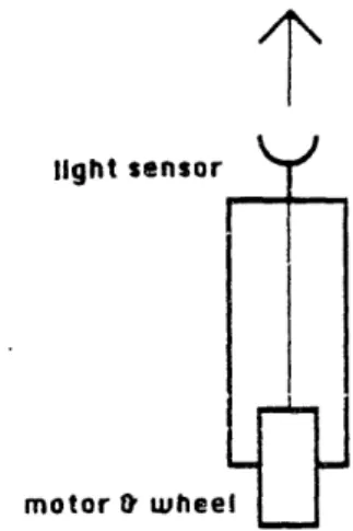
light sensor Y
FT
motor wheel
Figure 2.1: Braitenberg Vehicle No. 1
Braitenberg's vehicle No. 1 is shown in Figure 2.1. This vehicle consists of a light sensor connected (via a wire) to a motor. The more light received by the sensor, the faster the motor turns.
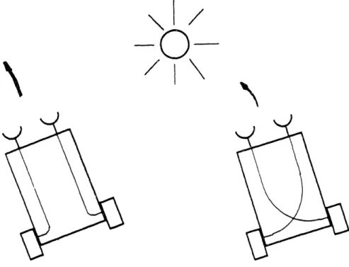
Vehicles No. 2a and 2b make use of two of these light-sensor-and-motor circuits, to form a vehicle that has the ability to turn (Figure 2.2). As indicated in Figure 2.3, these vehicles display either a positive or negative tropism to light.
Let's examine vehicle 2b. If a light is positioned to its left (as in the figure), then its left light sensor will be excited to a greater degree than its right sensor, and its right wheel will turn faster than its left wheel. This will cause the vehicle to turn towards the light; the sensor-motor interaction will continue to drive it toward the light.
In a complementary fashion, vehicle 2a turns away from the light. Proposed as a series of thought experiments, at least two projects have taken inspiration from Braitenberg's work. One is software designed for the Macintosh that allows some experimentation with early vehicles. The software is not very flexible and allows only rudimentary experimentation. A much more elaborate and powerful Braitenberg microworld is presently being developed by Roy Pea, Michael Eisenberg, and Franklyn Turbak (Pea
J %J
I I
LJ
-r-I
Li
Figure 2.2: Braitenberg Vehicles No's. 2a and 2b
Figure 2.3: Braitenberg Vehicles 2a and 2b Encountering a Light
I
L
-- J) I I
! J L ·
I~~~~~~
et al., 1988). Entitled "Creatures of Habit," it is a universe of interacting programmable "creatures" whose individual behaviors are guided by simple rules that may model naive psychology, physical laws, chemical affinities, and other domains. Using the system, students may create or revise crea-ture rules and explore resulting emergent behaviors within the 'artificial ecosystems."
A system called LEGO/Logo takes this "artificial animal environment" off the computer screen and puts it into three dimensions. Designed in a collaborative effort between LEGO A/S, a company based in Denmark, and Seymour Papert, Stephen Ocko, and Mitchel Resnick of M.I.T., LEGO/Logo is a building set consisting of LEGO plastic building materials - beams, blocks, gears, pulleys, wheels, and motors - and a computer interface involving sensors and Logo programming.
The materials are part of a learning environment for children, wherein they build motorized machines and then hook them up to the computer, thus enabling them to write programs to animate their constructions. The LEGO building parts are extremely versatile, as evidenced by the variety of machines children have constructed, including cars, dinosaurs, and roller-coasters.
Experience has showed that these materials can tap a wealth of creativ-ity in children. Many children who do not possess verbal or mathematical skills (and those who do) are able to use a form of "spatial intelligence" and knowledge of physical materials in LEGO/Logo activity. Often collab-oration occurs between children who combine LEGO skills and Logo skills
to accomplish a project (Ocko et al. 1988).
The LEGO/Logo system incorporates two types of sensors that can be built into LEGO machines: a touch sensor and a light sensor. Children
often will build a car, and then mount a touch sensor on its bumper. Then they can write a Logo program to cause the car to change direction when the touch sensor is triggered, as when the car hits a wall.
The LEGO/Logo system includes sensors, motors, and control (Logo programming), which are exactly the elements needed for explorations of cybernetics. However, each LEGO machine must be hooked up with wires to its computer, and it is difficult to write programs for more than one ma-chine at a time. These limitations constrain the extent to which mama-chines may interact with each other and their environment. And it exactly these interactions which are of most interest to the cybernetician.
Chapter 3
Programmable Bricks
3.1
Logo Bricks
In the original version of LEGO/Logo, a machine must be hooked up via long wires to a host computer, which is a desktop-sized personal computer. The limitations of this system led to the idea of a "computer-in-a-LEGO-brick" that could be built into the LEGO machine itself.
Hence, the development of the Logo Brick: a computer inside of a LEGO brick. One programs it in Logo, by hooking it up to a "large" computer that has a keyboard and screen. The Logo Brick can directly cnntrol up to four motors, and receive information from several sensors.
Figure 3.1 shows a picture of the Brick and its insides. The Brick measures 9 cm long by 5 cm wide by 3 cm high - about the size of a deck of cards. It is powered by a rechargeable battery pack of the same dimensions.
There are several implications for projects that are built using the Logo Brick, rather than using original LEGO/Logo. Machines can be designed for mobility without having to worry about tangled trains of wires. This encourages more "animal-like" inventions, instead of stationary machines.
The Logo Brick
Because each machine can carry its own program aboard the Logo Brick, multi-machine projects are possible without cumbersome program-ming techniques. Projects involving more than one machine often reveal un-predictable emergent phenomena from interactions between the machines, which are interesting to study.
Appendix A includes a history of the development of the Logo Brick and technical information on its use.
3.2
Sensor Devices
New sensors were developed for use with the Logo Brick. I will mention these devices briefly here, and explain their operation in more detail in the context of experiments.
* LEGO Touch Sensor. Responds to contact pressure. Same as in original LEGO/Logo.
* LEGO Light Sensor. Useful for certain tasks, but not used in any of the experiments with the Logo Brick.
o Sound Sensor. Responds to "beep" generated by small beeper unit. Allows signalling from one machine to another.
* Directional Light Sensor. Indicates direction of brightest incoming light.
* Threshold Light Sensor. Responds when incoming light surpasses an adjustable threshold.
* Analog-to-Digital Light Sensor. Reports a numeric value correspond-ing to the amount of light it is receivcorrespond-ing. None of the experiments made use of this sensor.
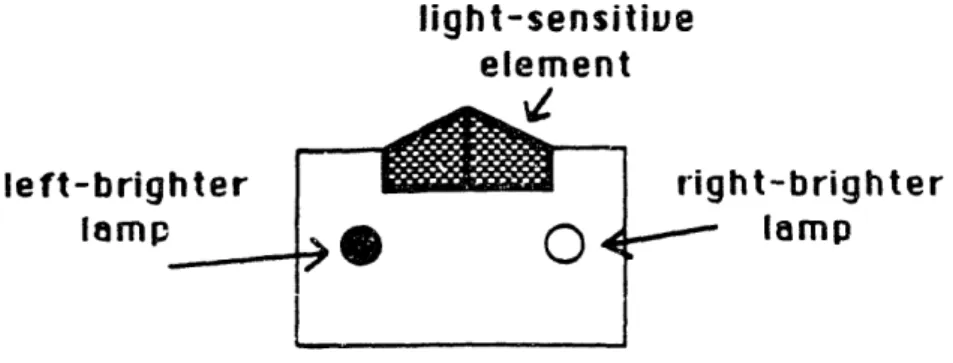
light-sensitive element -.49%Z le ft-brigh ter lamp right-brighter lamp
Figure 3.2: Illustration of Light Sensor
The directional light sensor played a centra! role in much of our exper-imentation.
This light sensor would indicate a difference in brightness of light: it would tell whether incoming light was brighter from a left-hand direction, or whether it was brighter from a right-hand direction. It would indicate this by lighting one of two small lamps, and by sending a corresponding signal to the Logo Brick (See Figure 3.2).
We used this sensor to design a behavior whereby a vehicle could follow a light. The vehicle would use the light sensor to correct its course repeatedly so as to point towards the brightest source of light. This behavior became the paradigm feedback process for the children to explore.
The indicator lamps were designed into the light sensor for the human experimenter's benefit when working with the device. These lamps indicate the state of the sensor, in order to help a person using the device to test what to what the device responds.
A similar feature was installed into the sound sensor. This device sig-nalled 'true" when it was hearing" a beep, but unless the Logo Brick using
_ [ _ _m~
----So I added a small lamp that would light when the sensor received the sound.
I chose to implement the sound sensor as the first wireless communica-tions device specifically because the mode of communication, a high-pitched tone, can be directly perceived by a person. Radio or infrared communica-tions would also have worked for a wireless communicacommunica-tions method, and have some advantages such as increased range, but I wanted a device whose sensory modality children could directly perceive and easily understand.
3.3
Braitenberg Bricks
In addition to the fully programmable Logo Brick, a set of hardware bricks were developed that allow construction of several of the vehicles described in Braitenberg's book.
These "Braitenberg Bricks" consist of a light sensor brick and a motor driver brick. When the light sensor is connected to the motor driver, the motor will turn at a rate proportional to the amount of light being received by the light sensor: the more light shining on the sensor, the faster the motor will turn
An additional inverter brick can be wired in the circuit between the light sensor and motor driver. The motor will then turn according to an inverse-proportional relationship: the more light received the slower the motor will turn.
An arrangement of two of these circuits can be used to make a vehicle that is either attracted to or repelled by a light source, as described by Braitenberg. in his vehicles 2a and 2b (Figure 2.2).
Chapter 4
Description of Experiments
The chapter outlines the series of experiments I led with two groups of children: fifth grade children at the James W. Hennigan school, and seventh and eighth grade children from the Fessenden school, a private school for boys in Newton, Massachusetts.
In this chapter I describe the activities that were set up for the children, explain how these activities were chosen, and indicate what I expected the children and the researchers' to gain from them. I wish to stress the exploratory nature of these experiments, on the part of the researchers as well as the children, and that I would classify this work as a pilot study.
Chapter 5 contains a narrative of what the children actually did in these experiments, and Chapter 6 presents an analysis of these activities.
4.1
Format of the Experiments
M.I.T. researchers worked with the Hennigan children beginning in Octo-ber, 1987 through June, 1988. There were varying numbers of research-ers/observers on hand at a given session; from two or three to up to ten
onlookers. Several of the sessions were videotaped.2 The sessions ran about once a week (one hour per session) from October to December, and about once every two weeks from February to June.
The groups of Hennigan children were taken from two "advanced work" fifth grade classes. The children in these classes were considered more capable in traditional school work than children in the regular classes. We chose children from this group deliberately, expecting them to learn how to deal with complex subject matter more quickly. We met with groups of four children from each of the two classes. Each of the groups consisted of two boys and two girls.
Two of the boys in one of the groups were asked to leave the group after one month. The other group of four was split into two groups of two (two boys and two girls) beginning in March, 1988. There had been a difficulty in the larger group that not enough of the children could participate at once; there was only enough hardware to support one computer terminal for which to program the Logo Bricks. The groups of two worked out much better.
The group of older children were seventh and eighth graders from a pri-vate school in Newton, Massachusetts. They were chosen for their interest and demonstrated ability by their computer teacher. I met with six boys over a period of four weeks for two two-hour sessions per week.
4.2
Research Methodology
The research was characterized by direct involvement in the children's ac-tivities. This strongly guided approach allowed me to go further in the use of the materials within the time period of experimentation. The children's
freedom was somewhat limited in this departure from earlier LEGO/Logo philosophy. Teachers using the original LEGO/Logo materials were encour-aged to allow children to invent their own projects as well as to build them (Ocko et al. 1988). In these experiments, I wanted to be able to steer the children into certain types of problem-solving situations.
There was an on-going process of examination of the experimental con-tent and style during the course of the experiments. Experiments were often planned after analyzing the previous week's activity, or were moti-vated by a new sensor device constructed at the M.I.T. laboratory. In one case, a project idea of the children led to the development of a sensor in order to realize that idea.
I was interested in finding out what the problems are; that is, conducting an in-depth survey, with new materials, to reveal what is interesting, and worth exploring further, about them.
4.3
Materials Used in the Experiments
4.3.1
Programmable Turtles
In order to focus on new activities using the Logo Brick, I felt it would be more efficient to give the children pre-constructed LEGO machines, which they could program, rather than have the children spend time on mechan-ical LEGO work. Therefore, I designed a vehicle for them to use in their Logo Brick activities.
I call this vehicle the Programmable Turtle. It is the LEGO equivalent of the Logo turtle in that it can move in a similar fashion: forward and
touch bumpers for sensing collisions. Figure 4.1 shows a picture of the Programmable Turtle.
A variety of sensors were used in the experiments. These sensors were plugged into the Logo Brick and then mounted physically on the Pro-grammable Turtle. The following devices were added onto the Turtle during the course of the experiments: lights, a beeper, a light sensor (two kinds), and a sound sensor.
4.3.2
Programming Tools
To make the Programmable Turtles easier to use, I designed a set of pro-gramming tools, which I called the "Tools Words," for communicating with the Turtles.
Using the primitive operations of the LEGO/Logo language, one must give instructions explicitly to motors and sensors. For example, to make the Turtle go forward, one would have to give instructions to turn on both the left motor and the right motor. The LEGO/Logo commands: to do this are:
TALKTO A B] SETEVEN ON
The first command, TALKTO, tells the computer to send commands to the motors labeled A and B. The second command, SETEVEN, sets those motors in the even" direction, which is wired on the turtle for forward. The final command, ON, turns the motors on.
I encapsulated all of those instructions into a single Tools Word, named GOFD (for GO ForwarD). The full set of Tools Words that I gave to the children included words for moving the turtle forward, backward, left, and
-- 1- 1 - 1
-:: : .;::. I 'G;" "":''
heel
Figure 4.1: Programmable Turtle with Logo Brick and Battery Pack ··1·
· · : ·
·· ···'·· ·· ' ''
right, and for inputting information from the touch sensors and light sen-sors.
This sort of module construction is a commonly accepted programming practice; the Logo language was specifically designed to support this sort of construction. Once you have written a tool, you can forget" about how the work is done.
Unfortunately, I did not introduce the Tools to the Hennigan children until the springtime. Several of the earlier experiments consisted of work-ing out low-level details; this work was unnecessary and could have been avoided by introducing the Tools earlier on. I introduced the Newton chil-dren to the Tools in their first session with the Logo Brick without causing them any confusion.
4.4
Description of Experiments: Hennigan
Children
The Hennigan children were already familiar with the original LEGO/Logo materials, so we planned the first session to be a review of LEGO/Logo.
In the next session we planned to introduce the children to the Logo Brick, and teach the children how hook the Brick up to an Apple IIGS computer, how to send it commands, and how to write Logo programs for it.
We wanted to introduce the children to the Programmable Turtles using a sensor that they were already familiar with, so we chose a project using the touch sensors. The task for the children was to write a program that would make the Turtle back up and change direction after it had run into something.
We then introduced the directional light sensor. As mentioned earlier, this light sensor indicates direction of brightest light (either towards the left or towards the right) by lighting a small lamp and reporting a value to the Logo Brick.
We asked the children to uise this sensor to make the Turtle either seek the light or avoid the light.
When this had been accomplished, we began a series of sessions to explore the behavior of the light-seeking turtle. Children were given several sorts of lights, including blinking lights, steady lights, and flashlights. We suggested experiments such as positioning two lights of equal brightness at different distances from the Turtle, or placing a bright light far away and a dimmer light nearby. The children were invited to think aloud about these problems, and then perform an experiment to see what the turtle would do. We expected these experiments would allow us to explore the children's theories about how the turtle "follows the light."
After about six weeks of sessions, we began more in-depth projects with each of the two groups of children.
In the group of four children, I encouraged them to think about a project that would use more than one Logo Brick. The previous series of exper-iments involved one Turtle performing a certain behavior, with a fairly fixed environment. I expected to encounter interesting issues in projects that involved interactions between two Logo Bricks.
4.4.1
The Baseball Game
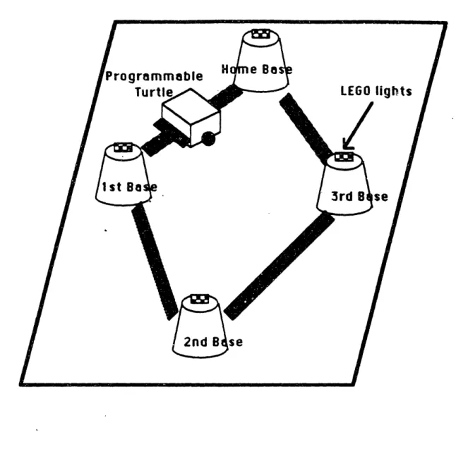
The children's plan was to have the turtle run around a baseball dia-mond, with lights mounted at each of the four bases. The Programmable Turtle would run a light-following program that would cause it to head toward the nearest lighted base. A Logo Brick "outfield" would sequence the lights so that the turtle would would head for each base in the proper order.
As the children were discussing the project, I conceived of a new sensor that would be very useful for the project. I then explained this idea to the children.
The project could use a sound sensor for signalling from the turtle to the outfield. I suggested how the sound sensor could be incorporated into the project: when the turtle hit one of the bases, it would sound a beep. The outfield Logo Brick would use the sound sensor to "hear the beep," and switch the light to the next base.
4.4.2 The Turtle Racetrack Game
In the other group of (now two) children, I brought in a "Turtle Race Track," with a plastic-tape road and styrofoam cup pylons. I gave the children the task of placing and then programming a series of lamps on the edge of the road so that a light-following Programmable Turtle would stay on the course. In this experiment, I hoped to test further the children's notions about the light-following properties of the turtle, and have the children explore interactions between the Turtle and another Logo Brick.
4.4.3 Two-Turtle Experiments
The experiments described so far took place through December of 1987. We took a break from the sessions and resumed in March of 1988. I then
encouraged the children to think about projects involving two or more in-teracting turtles. I felt that interactions between mobile creatures would reveal even more interesting phenomena than we had seen the the previous projects.
Some of the ideas we generated were:
* A "turtle ballet" with several turtles performing dances. orchestrated by a turtle maestro."
* Turtle hide-and-go-seek with two turtles.
* Turtle tag, with several turtles. One turtle would be it," and would chase the other turtles. When it hit one of them, then that turtle would be it."
We decided to work on a two-turtle version of the tag game. One turtle would chase another turtle, and when the first "caught" the second, the first would beep. The second turtle would hear the beep," and then would begin to chase the first turtle, which would be trying to escape. The turtles would carry lights and use a light-following procedure in order to find each other.
I suggested to the children that they could use the "brightness sensor" (the threshold light sensor) in this project. -This sensor could be used to help the chasing turtle know if it had hit the other turtle, rather than some other obstacle. After it had collided with something, the turtle could check if the brightness sensor were on, in which case it would be likely to have hit the other turtle, which would be emitting light.
4.4.4
Braitenberg Experiments
In my last session with the Hennigan children, I brought them a turtle equipped with the Braitenberg apparatus described earlier. I wired the turtle for two different behaviors - follow and avoid - and asked the children to experiment with the turtle and describe its behaviors. I encouraged them to make comparisons with the Logo Brick turtles.
I expected the experiment with the Braitenberg turtle to test the ro-bustness of the children's theories about the light-following process, and to show if they could generalize from their experience with the Logo Brick turtles.
4.5
Description of Experiments: Newton
Chil-dren
These sessions were led by me, with assistance from Philip Ivanier. They took place in a computer classroom at the Newton school. with a group of six boys in the seventh and eighth grades.
4.5.1
LogoWriter Screen Robots
This activity was intended as an introduction to robots and robotic sensors, prior to work with the Logo Brick and Programmable Turtles.
I suggested that the Logo screen turtle could be thought of as a robot. It had several sensors with which it could explore its environment (the Logo graphics screen). We would focus on the use of COLORUNDER, a LogoWriter primitive which reports the value of the color currently underneath the tur-tle. The turtle could navigate around the screen, and treat one color (black)
as free space," while another color (white) would indicate an obstacle to be avoided.
The next stage of the activity consisted of developing movement strate-gies for the turtle. Once the children could teach the turtle to sense white space as an obstacle, they could try to teach it to maneuver around those obstacles.
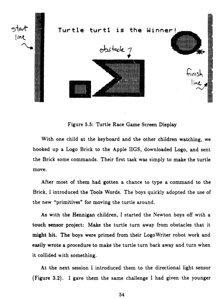
The final stage of the project was a competition. I wrote software to pit the children's turtles against each other in a race. Several turtles played the game at once; the first turtle to make it across the screen, successfully navigating around obstacles, would be the winner.
This screen robot project served several purposes:
1. It gave the children a Logo refresher."
2. It was an introduction to the ideas of robots and sensors, in a domain (software and screen graphics) in which the students were already familiar.
3. It allowed the children to engage in problem-solving activity as they developed strategies for their turtles.
4.5.2
Programmable Turtles
These children had no prior experience with LEGO/Logo. I planned the first session to be a thorough introduction to the Logo Brick, covering the following topics:
. the Programmable Turtle as a vehicle for Logo Brick projects; * the Tools Words for ease of interaction with the Turtle.
As with the Hennigan children, I chose a touch sensor project for the boys' first programming project for the Programmable Turtles. I thought that touch sensors would be the easiest for them to understand.
The following session, I planned light sensor projects using the direc-tional light sensor. I gave the boys the challenge of writing programs to make the turtles follow the light.
In the final session, I introduced the sound sensor and beeper, and encouraged the children to write programs to make two turtles interact.
The Braitenberg materials were not tested with the Newton school chil-dren.
Chapter 5
Narrative of Experiments
In this chapter I tell the story of the experiments that were done with the children.
5.1
Experiments with Hennigan Children
The Hennigan children began in two groups of four children each': I Patti, Jeanne, Larry, and Sam
* Elizabeth, Claudia, Bill, and Matt
After one month of work, Bill and Matt left the series of experiments. In the spring, at the beginning of the two-turtle projects, I split the group of four into two groups: Patti and Jeanne, and Larry and Sam. I was not able to meet with the other two girls in the spring because of scheduling difficulties.
5.1.1
Introductory Work
The children were given the LEGO/Logo primitives and asked to do some simple tasks, such as making the ferris wheel spin a certain number of times, or making the car rebound when it hit a wall. They reviewed many of the same LEGO/Logo primitives that they would use with the Logo Brick: TALKTO, ON, OFF, ONFOR. RD. SENSOR.
5.1.2
Logo Brick: Motors, Touch Sensor, and Light
Sensor
In these sessions the children were introduced to the Logo Brick. They were told that it was a full computer and that to communicate with it, they would connect it to a "big" computer - the Apple IIGS. We opened one up for them so they could see the circuitry inside.
With the Logo Brick mounted on the back of a turtle, the children were shown how the connect it to the Apple IIGS computer. They learned the syntax of the interface while sending motor commands to the turtle, getting it to move in different ways. The first challenge was how to get the turtle to turn, which was solved by either turning on only one motor at a time, or turn both motors on, but in opposite directions.
I asked the children what the turtle could do, using the touch sensors mounted on the front of the turtle. They responded with the obvious thing: Make it turn when it hits something. However, the task of specifying this in Logo was not so easy.
With considerable help, the children came up with a procedure that would make the turtle go backwards for a few seconds after it hit something. Then it would go forwards again.
The children immediately fell in love with the little animal" that they had just designed. They crawled around the floor chasing it and pressing
its bumpers to watch it go backwards. Then they forced it into retreat with their enthusiasm, making it go backwards repeatedly so it backed up underneath a cabinet! Finally they let it get away.
Next we began a series of sessions making use of the directional light sensor. The children began to explore the behavior of the light sensor, using a flashlight I gave to them. They saw that when the flashlight was aimed from the left-hand side, the left-mounted lamp would light, and when the flashlight was aimed from the right-hand side, the right-mounted lamp would light. Also, they saw that if they shined the flashlight head on, they could get both lamps to light. Continuing, they found that by using their hands to block the overhead room lighting, the "other-side" lamp would light, indicating that the other side was brighter, which was the case.
I asked the children if they could think of any uses for the light sensor. Patti, remembering how the turtle would crash into things and then back away from them, said, It [the turtle] might crash into it [a light], and then when it senses the light it heads away." In the other group, I gave the suggestion of using the sensor to follow a light.
I helped the children towards a procedural description of how to follow or avoid the light, by asking: Suppose the light's here, coming in from the left (I pointed the light from the left, to light the left lamp), what would we want the turtle to do? And then, if the light is coming in from the right, what would we want the turtle to do?"
Soon the children saw that when the light was coming from the left side, we would want the turtle to move towards the left, and when the light was coming in from the right, we would want it to move to the right. The final step was to see that these actions would have to be repeated, so that the
turtle would continually check whether it should take a step to the left or a step to the right. The resulting program we made was essentially this:2
TO FOLLOW
IF LEFT.BRIGHTER? [STEP.LEFT] IF RIGHT.BRIGHTER? [STEP.RIGHT] FOLLOW
END
The children began to explore the behavior of the turtle using the flash-light, their hands (blocking the light sensor), and a few hand-held lamps. With four children sticking objects into the turtle's nose" there was total chaos, and no one could tell what was going on. So we told the children to use only one lamp, and see if they could tell what the turtle was doing.
Soon they found that it was avoiding the light; that it was turning in the opposite direction that the light was held. They changed the program so that it would turn on the other motor depending on the sensor, and tried again.
Over the next several sessions, we asked the children to consider various modifications to the turtle's environment, while keeping the turtle's pro-gram the same. What would happen if there were two lights on the table, both of equal brightness? Which one would the turtle follow? What if one were closer than the other, or if one were brighter than the other? The children were invited to think aloud about these problems, and then run the experiment to see what the turtle would do.
One of the child-en, Bill, saw that once the turtle got closer to one of the two equal-brightness lamps, it would then follow that one. But Matt
21 have modified the copy of the program for readability but the content is the same. In our first versions of this program, the sensor words LEFT.BRIGHTER? and RIGHT .BRIGHTER?, and the motor words STEP. LEFT and STEP .RIGHT were done by specific
explained that the turtle would follow the real light" while ignoring the "fake one." He was more mystified as to how the turtle chose which light it would follow, attributing it more to a random selection.
When asked how to make the turtle turn in a circle, Elizabeth invented an interesting way of modifying the turtle, using hardware rather than software. She attached one of the small battery-lights, which she had been holding in her hand, onto the turtle's ear" - adjacent to the light sensor. With the light constantly shining on the light sensor, the turtle kept turning towards that side, and made a circle.
Then she made the light flash, so that when it flashed on, the turtle would turn in that direction, and when it flashed off, it would follow the room light. The turtle manifested a -very random wandering effect.
5.1.3
The Baseball Game Project
Over the course of several sessions, the children constructed a playing-field out of cardboard, paper, and tape, with styrofoam cups for the bases. They mounted two LEGO light bricks (small flashlight bulbs encased in plastic) on each base. Meanwhile, back at M.I.T., an undergraduate student and I worked on developing the sound sensor and its matching beeper.
Figure 5.1 shows a sketch of the children's creation.
As the children were building their playing field, they spent time dis-cussing the tasks to be performed by the base-running turtle and the out-field computer. This was a challenging problem, and I suggested that the children role-play the two parts in order to help them understand how the two Logo Bricks would interact.
receive and transmit information. So it became difficult for the children to formalize their strategies into computer programs.
The key to helping the children write Logo procedures was to use sub-procedures. They first made a main procedure, which read like a script. Later, they wrote the code for the sub-procedures, filling in the details of the script.
5.1.4
The Turtle Racetrack Game
Figure 5.2 shows a drawing of the racetrack board.This project had two phases. In the first phase, I gave the children five lights and a switch panel to turn them on. The children positioned some of the lights along the edge of the track, and used the switch panel to flash the lights in sequence. It was an easy task to guide the turtle along the path.
In the second phase of the project, the children plugged the lights into a Logo Brick. They then wrote a Logo program to turn the lights on in sequence. But, they paid little attention to the timing.
After discussion with the researchers, the children ran an experiment where they timed the length of time the turtle took to navigate the course from lamp to lamp. Then they converted those measurements into ONFOR statements in Logo. The project was eventually a success.
5.1.5
Two-Turtle Experiments
Top View
-Finish I IJ %a . _- - _ StartI
Figure 5.2: Sketch of Turtle Racetrack
I
R
As we were discussing how the two turtles would interact, Patti observed that the two of them could use exactly the same program, except that one would be doing the chase part while the other would be doing the escape part.
We had gotten to the stage of being able to recognize" the other turtle, using the threshold light sensor, when the school year ended.
5.1.6
Braitenberg Experiments
I explained each of the components to the children - the light sensors, the motor control bricks - and how to wire them together (we did not use the inverter bricks). I then showed them how to wire both of a turtle's motors to the same light sensor, making a vehicle like Braitenberg's vehicle no. 1 (Figure 2.1). The turtle would move straight forward, with its speed dependent upon the amount of light that the children delivered to it using a flashlight.
After they discovered the basic relationship of more light to more speed, I wired the turtle for either a Braitenberg follow" or Braitenberg avoid" scheme. I asked the children if they could figure out what the turtle would do.
At first it seemed like the turtle was following the light, no matter how it was wired, because any light shined on the sensor would cause the turtle to advance. I asked them to check if it were following the light, and Patti made a comparison to the follow scheme performed by the Programmable Brick turtle. She blocked off one of the turtle's light sensors ("no light") and shined the flashlight directly into the other light sensor. Then she
this case, the turtle turned towards the light, so she concluded, correctly,
that it was following the light.
I asked the children if they saw any other similarities between this turtle and the Logo Brick turtles they had used. Sam commented that UYes, they are similar, because they follow the light in the same way. But they are different because the Logo turtle you have to program, and this turtle you just wire up."
5.2
Experiments with Newton School
Chil-dren
5.2.1
LogoWriter Screen Robots
Most of the children had a considerable background in computers, including Pascal, Logo, and word-processing. However, I surmised that most of their experience was of the cut-and-dried programming class variety.
I started the boys off with a review of Logo and and introduction to the special features of LogoWriter. Each of the six boys was given his own LogoWriter disk, so that he could continue work after our sessions.
In the first session we covered the basic turtle movements, and reviewed how to draw geometric objects using REPEAT statements. Then I showed them how to use FILL to color in their figures. They also asked for the set color primitive (SETC), and they learned how to make their own shapes using the shape editor.
I then led a discussion in which we talked about robots and robotic sensors. I held up one of the LEGO turtles, and pointed out its touch sensors. We named some other devices that had sensors: electric doors
that used a weight sensor, door-bells that used a light sensor. Then I told them that the Logo turtle also had a "sensor": the COLORUNDER primitive. I suggested to the boys that the turtle could use COLORUNDER to navigate around the screen. Suppose black, the background color, were considered free territory, but white objects were obstacles. When the turtle encoun-tered a COLORUNDER equal to white, then it would know that it had hit an obstacle.
We set off to make procedures that would draw a smattering of white geometric obstacles on the screen. When all of the boys had accomplished this, I gave them a Logo procedure that would cause the turtle to advance slowly, until it hit a white object. Then the turtle would stop.
WVe called the procedure HUNT: TO HUNT
FD 2
IF COLORUNDER = :WHITE [STOP]
HUNT END
The procedure begins by advancing the turtle two steps. Then it checks if the color under the turtle is equal to the white color. If it is, the procedure exits and the turtle stops moving. Otherwise, the procedure "runs itself" again, causing the process to repeat.
The boys were terribly excited as they each got this working. Sure enough, the turtle would creep across the screen, and as soon as it hit something - presto! - it would stop. It was quite a thrill.
is too easy," and it was, since that was what they had just done in class, so I asked them to think about how to make the turtle find the obstacles, not just wunder around.
When I came back in two days, the children had been working furiously on their turtle programs. They all had procedures that would cause the turtle to turn when it found an obstacle, not simply stop. I pointed out to them how they had each invented different strategies for dealing with the obstacles. One child's turtle would turn left ninety degrees when it hit an obstacle, one would turn right one hundred degrees, and another would make an about-face, turning one hundred and eighty degrees.
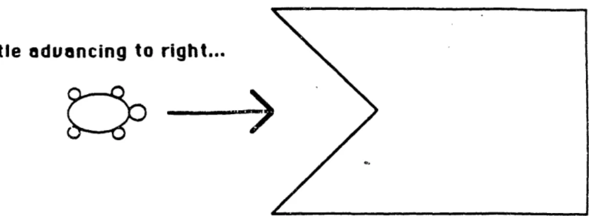
Now I gave them a new task: Make a turtle that can advance from the left side to the right side of the screen, running around obstacles that it may encounter. I posed it as a race: pretend there were a "finish line" on the right-hand edge of the screen, and the first turtle to get there would win.
The children set to work. Within a half-hour, most of them had invented algorithms that would successfully steer their turtles around square-shaped and circle-shaped obstacles. They all invented variations of the same theme: Go forward, until your turtle hits something. Then move backwards and upwards, and then try to go forward again. (In this case, forwards" means left-to-right, i.e., towards the finish line.)
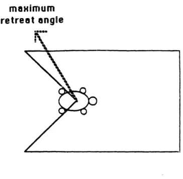
At that point, I gave them a new kind of obstacle to think about, one that was not so friendly as a circle or a square. It was a trap: once the turtle got in, it would have to go diagonally backwards to get out (see
Figure 5.3).
This obstacle provided a difficult challenge for all of the children. None of them were able to solve it completely; the best solutions were only able