IMPROVED PROPELLER
PERFORMANCE
by
LAWRENCE J. BOWLING
B.S., Ocean Engineering, United States Coast Guard Academy
SUBMITTED TO THE DEPARTMENT OF OCEAN ENGINEERING IN PARTIAL FULFILLMENT OF THE
REQUIREMENTS FOR THE DEGREE OF MASTER OF SCIENCE IN
NAVAL ARCHITECTURE AND MARINE ENGINEERING AND
MASTER OF SCIENCE IN MECHANICAL ENGINEERING at the
MASSACHUSETTS INSTITUTE OF TECHNOLOGY June 1987
Copyright (c) 1987 Massachusetts/]nstitute of Technology 1 e Signature of Author Departn4 t of Ocean N Engileering June 1, 1987 Certified by
Pr 4ssor Justin E. Kerwin
7
I Thesis Supervisor
Accepted by
Accepted by
MASSACHUSETTS INSTITUTE OF TECHNOLOGY
Professor David I Wilson k- Thesis Reader, Meqhanical Engineering - - Douglas Carmichael Chairman, Departmental Graduate Committee Department of Ocean Engineering
JUI.
z
z
1987
LIBARIES
IMPROVED PROPELLER
PERFORMANCE
by
LAWRENCE J. BOWLING
Submitted to the Department of Ocean Engineering on June 1, 1987 in partial fulfillment of the requirements for the degree of Master of
Science in
Naval Architecture and Marine Engineering and
Master of Science in Mechanical Engineering.
Abstract
The inclination of a propeller shaft relative to the fluid inflow results in a once per revolution tangential velocity fluctuation in the plane of the propeller. A more desireable condition from the view point of efficiency and cavitation considerations is to have a more uniform tangential inflow. A nine bladed non-axisymmetric stator was designed based on a lifting line computer code for multi-component propulsors. The stator, 1.2 feet in diameter, was designed to operate with DTNSRDC (David Taylor Naval Ship Research and Development Center) model propeller 4497, which is one foot in diameter.
Experimentation with the aluminum stator model was conducted to validate the design and the computer program wake predictions. Laser Doppler Anemometry (LDA) was used to measure the velocities at several radial locations in a plane behind the stator where the propeller would operate. Comparisons were made between the measured propeller inflow wake and the computer predicted inflow wake. Non-dimensional circulation measurements about the blades of the stator were also made to provide data for comparison to computer generated predictions. The stator was tested in an axisymmetric and non-axisymmetric blade alignment. The experimental results validated the computer wake predictions for the tangential wake in the plane of the propeller. The results support a conclusion that the non-axisymmetric stator would induce velocities in the plane of the propeller to counteract an inclined flow. The LDA measurements of the tangential wake indicate that the velocity fluctuation would be reduced by the non-axisymmetric stator.
combination. Accounting for increased drag due to the stator, the stator/propeller propulsor was more efficient than the propeller operating by itself.
Thesis Supervisor: Title:
Professor Justin E. Kerwin
Dedication
I wish to acknowledge and thank several individuals for their assistance in helping me perform this work. Without their effort and advice, this thesis would not be at a stage of completion. Primary thanks go to Professor "Jake" Kerwin for suggesting this experiment and offering me the opportunity to develop it. The construction of the stator model and the performance of the experiment had associated costs which were not inexpensive. In this financial regard, thanks are extended to the U.S. Navy for their portion of the funding of this effort. The author hereby grants full permission to the U.S. Government and its agencies to reproduce and distribute this thesis document.
The computer analysis required before and after the experiment was made possible by the programs developed primarily by Bill Coney and Ching-Yeh Hsin. The design of the stator and the performance of the experiment were greatly facilitated by Mr. Dean Lewis. Lastly, sincere thanks to my wife, Michelle, and my daughter, Amberly, for tolerating my lifestyle and moods of the past two years.
Table of Contents
Abstract 2 Dedication 4 Table of Contents 5 List of Figures 7 List of Tables 8 1. INTRODUCTION 9 2. PROBLEM STATEMENT 11 3. STATOR DESIGN 153.1 MIT MHL Computer Programs 15
3.2 Design Considerations 20
3.2.1 Stator Blade Number and Planform 20 3.2.2 Axial Separation Distance of Components 23
4. DESCRIPTION OF EXPERIMENTAL FACILITY 26
5. DESIGN OF THE EXPERIMENT 27
5.1 Scope of the Experiment 27
5.2 Modeling Inclined Flow 28
5.3 The Stator Model 29
5.4 Operating Conditions 31
6. EXPERIMENTAL RESULTS 32
6.1 Hub Vortex Strength 32
6.2 Axisymmetric Testing 35
6.2.1 Non-Dimensional Circulation Measurements 35
6.2.2 Flow Field Measurements 37
6.3 Non-Axisymmetric Testing 40
6.3.1 Non-Dimensional Circulation Measurements 40 6.3.2 Non-Axisymmetric Flow Field Measurements 43
6.4 Propulsive Efficiency 49 7. CONCLUSIONS 55 7.1 Experimental Summary 55 7.2 Discussion 56 Bibliography 58 Appendix A. PLL OUTPUT 60
Appendix C. OPEN-WATER TESTS 74
Appendix D. SSF-1 OUTPUT 86
Figure 2-1: Tangential Wake Variation. 11 Figure 2-2: PLL Wake Predictions at Various Radii. 14
Figure 3-1: PLL and SSF-1 Circulations 18
Figure 3-2: PLL and SSF-1 Circulations 19
Figure 3-3: Hub Assembly 24
Figure 3-4: Stator Blade 25
Figure 5-1: Desired Test Results 29
Figure 5-2: Stator Mounted in Water Tunnel 30
Figure 6-1: Hub Vortex Comparisons 34
Figure 6-2: Experimental & Axisymmetric Circulation 36 Figure 6-3: Circulation Distribution Comparison 38 Figure 6-4: Tangential Wake - Axisymmetric Stator 39 Figure 6-5: Radial Locations for Velocity Measurements 40 Figure 6-6: Experimental & Non-Axisymmetric Circulation 42
Figure 6-7: Tangential Wake, r/R = .45 44
Figure 6-8: Tangential Wake, r/R = .60 45
Figure 6-9: Tangential Wake, r/R = .75 46
Figure 6-10: Revised PLL Tangential Wake 48
Figure 6-11: Propeller 4497 Open-Water Test 50 Figure 6-12: Stator/Propeller Open-Water Test 51
List of Tables
Chapter 1
INTRODUCTION
The propulsion plant design and installation on ships of all sizes leads to the condition were the propeller shaft often penetrates the hull at a slight downward angle as measured from horizontal. A reason for this shaft inclination is to allow for adequate clearance between the hull form and the tips of the rotating propeller blades, without requiring an excessively long shaft. The shaft angle produces inclined flow which yields a once per revolution tangential velocity fluctuation in the plane in which the propeller blades are rotating [3]. This condition detracts from the operating efficiency of the propeller. Specifically, it can lead to the inception of cavitation at lower speeds when compared to propellers operating under the same conditions but in a more uniform inflow. Cavitation increases the drag on the propeller blades which results in an increased torque and reduced propulsive efficiency. Cavitation can eventually lead to physical damage to the blade surface. Improved propeller performance in terms of propeller efficiency, q, and increased operating speed before the inception of cavitation are the rewards for the development of a device which can minimize or reduce the effects of inclined flow due to shaft inclination.
The design of a pre-swirl stator, to be used in conjunction with a model propeller, DTNSRDC propeller 4497, is the focus of this experimental thesis effort. The design was developed with the use of existing MIT Marine Hydrodynamics Laboratory (MHL) propeller lifting line codes. While unable to exactly model inclined flow in the laboratory, an experiment was designed to test the stator and provide results to validate the design and the computer lifting line code. The
experiment was designed to demonstrate the propulsive efficiency of the stator/propeller combination and to map the inflow wake to the propeller for comparison with computer predictions. By achieving the desired flow field mapping in the plane of the propeller, it would be demonstrated that the stator was modifying the flow to counteract inclined flow.
Chapter 2
PROBLEM STATEMENT
As mentioned in Chapter 1, the flow resulting from a propeller shaft angle exhibits a once per revolution velocity fluctuation. The harmonic is in the tangential direction as considered in the propeller blade frame of reference. The flow situation can be better visualized by referring to Figure 2-1.
SHAFT ANGLE * INFLOW (VS) 1 80
Vt
-," 362Figure 2-1: Tangential Wake Variation.
The amplitude of the fluctuation is a function of the shaft angle and the ship speed. The goal of this experimental effort was to design a non-axisymmetric stator with a prescribed radial circulation distribution which would induce tangential velocities in the plane of the propeller to minimize those velocity variations experienced due to shaft angle. A shaft angle of seven degrees was assumed for
purposes of the experiment. The desired result would be to achieve a deflected flow to counteract the shaft angle inclination. Additionally, it was desired to achieve this inflow modification and increase the efficiency of the propulsor combination after taking into account the increase in drag due to the stator.
A model propeller, DTNSRDC propeller 4497, was selected for use in the experiment. This propeller was available for use in the MIT MHL. The propeller, by virtue of its existing physical geometry and pitch angles, has a design circulation distribution. This distribution was established by Boswell [2]. The characteristics of DTNSRDC propeller 4497 are presented in Table 2-I.
Table 2-I: Characteristics of DTNSRDC Number of Blades:
Expanded Area Ratio: Hub-Diameter Ratio: Section Meanline:
Section Thickness Distr: Design Advance Coefficient:
c/D tan Bi P/D Skew 0.174 1.8256 1.455 0.0 0.202 - 1.444 2.33 0.229 1.3094 1.433 4.65 0.275 1.0075 1.412 9.36 0.312 0.8034 1.361 13.95 0.337 0.6483 1.285 18.38 0.347 0.5300 1.200 22.75 0.334 0.4390 1.112 27.14 0.280 0.3681 1.027 31.57 0.210 - 0.985 33.79 0.000 - 0.942 36.00 Propeller 4497 [5] 5 0.725 0.2 NACA a = 0.8 NACA 66 (Modified) 0.889 t/D f/c 0.0434 0.0430 0.0396 0.0395 0.0358 0.0370 0.0294 0.0344 0.0240 0.0305 0.0191 0.0247 0.0146 0.0199 0.0105 0.0161 0.0067 0.0134 0.0048 0.0140 0.0029
-The first task in approaching the stator design problem was to determine the required radial distribution of circulation for each of the stator blades which would modify the inflow to improve the propeller's performance in inclined flow. To
r/R 0.20 0.25 0.30 0.40 0.50 0.60 0.70 0.80 0.90 0.95 1.00
establish these circulation distributions for the stator blades, extensive use was made of the MIT MHL propeller lifting line computer code called, appropriately, Propeller Lifting Line (PLL) [8]. The PLL code, which can accomodate multiple component propulsors, uses an optimization procedure which results in the radial circulation distributions for the individual propulsive components. Additionally, a program option allows the required non-axisymmetric analysis to be studied. More
about the use of PLL will be discussed in Chapter 3.
The anticipated modification to the propeller inflow as predicted by PLL is also shown in Figure 2-2. A comparison of the tangential inflow wakes with the stator and without the stator shows that there are more fluctuations per revolution in the tangential inflow wake with the stator. However, the more significant observation is that the predicted amplitudes of these variations with the stator in place are much less. This is the desired modification to the inflow for which the stator is to be designed. As mentioned earlier, a further consideration in the design of the stator/propeller propulsor was to achieve a propulsive efficiency greater than or equal to the propeller operating by itself. By designing a stator which introduces circulation into the flow which is opposite to the circulation provided by the propeller, there is less rotational energy left in the wake. The result should be an increase in propulsive efficiency. The performance of the propeller and the stator/propeller open-water tests would provide the necessary data for propulsive efficiency analysis.
r.92.9 TANGENTIAL WAKE - .-WITHOUT STATOR -. s SWITH 5STATOR
.----._
.
....
_.9
r-0. 741 - s W,. 1 1 e46 1 ! eI se r ru. .52va
... -
v
---
0.
8
1.002 . ,2-.. zes2.20 1e2. 9V V 24e. se.e
Chapter 3
STATOR DESIGN
3.1 MIT MHL Computer Programs
This experimental thesis effort would not have been possible without the availability of the MIT MHL computer codes. With the design problem clearly defined, numerous computer runs were made with PLL to determine the radial circulation distribution required on each stator blade.
Prior to being able to obtain the "optimum" stator circulation distribution from PLL, it was necessary to prepare appropriate file inputs for the computer program for both the stator and the propeller. The design circulation on the model propeller was determined using another MIT propeller code, LLL-2. With this information, an appropriate input file for PLL was prepared. One difficulty experienced in using the circulation optimization procedure for this experiment, was that PLL optimizes circulation for both components, the stator and the propeller. The desired result was to obtain the stator's optimum circulation, given a prescribed circulation on the existing propeller. To overcome this situation, PLL was first run optimizing circulation for both components. The optimized propeller circulation from PLL was compared to the input design circulation. There were differences, but not significant as to invalidate the PLL output. The next run of PLL was performed without selecting circulation optimization. The previously determined stator optimum circulation and the design circulation for the propeller were prescribed as inputs. The results of this run were not significantly different from the previous one. This iterative technique deviates from the ideal design
situation which would be to design both a stator and a propeller for use as one propulsive unit.
The first stage of use of PLL results in optimum circulation distributions for the stator in an axisymmetric blade arrangement with a propeller. In the axisymmetric case, all blades of the stator have the same circulation distribution. A sample output from PLL for the axisymmetric case can be found in Appendix 1. At this point in the program, PLL allows for the non-axisymmetric analysis necessary to study the stator effects on inflow to the propeller considering inclined flow. Beginning with a mean circulation distribution obtained from the axisymmetric case, the program allows the user to vary this distribution until the desired modification to the inflow is obtained. The program outputs include the local circulation distributions at various radii for every blade on the stator. Appendix 1 also contains a sample output for the non-axisymmetric analysis.
To obtain this axisymmetric circulation distribution on a stator blade, 2-dimensional wing theory was used ar a rough estimate to determine the angle of attack required at each local radii. The non-dimensional circulation from the PLL axisymmetric case resulted in a varying angle of attack from hub to tip in the stator blade. The varying angle of attack translated to a twist in the stator blade. It was later determined with a stator analysis program, SSF-1, what angles of attack would be required in 3-dimensional flow to produce the required circulation distributions. This program and its analysis had not been developed at the time that the physical geometry of the stator was being determined..
After construction of the model, the program SSF-1 was available to determine the actual radial circulation distributions on the stator blades accounting for 3-dimensional effects. The effects of the 3-dimensional analysis of SSF-1 were significant and dominated the earlier 2-dimensional estimation. The
axisymmetric circulation distribution from SSF-1 was shifted further from the hub than the distribution obtained from PLL. See Figure 3-1. Additionally, for the axisymmetric case, SSF-1 was used to determine an angle of attack of thirteen degrees to obtain a circulation distribution similar to PLL. Thickness effects were taken into account. Anticipating adjustments to the required angle of attack, the hub assembly which holds the stator blades was designed to allow each blade to be independently set at any desired angle.
For the non-axisymmetric case, SSF-1 was used in a trial and error fashion, varying the angles at which each blade were set. The goal was to duplicate the PLL non-axisymmetric circulations which produced the desired inflow. The initial thought concerning the non-axisymmetric circulation distributions was that their shape on all blades would be very similar. It was felt that by adjusting the angle of attack of the entire blade the desired distribution could be approximately obtained. An exact match was not able to be obtained for all blades due to 3-dimensional effects. However, an excellent match was achieved on three blades, a very good match was achieved on two blades, and an acceptable match was obtained on the remaining four. These four were the most lightly loaded blades. An attempt was made to match the magnitude of the maximum circulation for these blades, despite the different shape of the distribution. Due to the fact that these blades were very lightly loaded, a possible alternative would have been to remove these blades completely during the experiment. This was not done. Figure 3-2 shows this comparison. Only five blade circulations are shown as, due to symmetry, the remaining four are identical to those plotted. In effect, the real "designing" of the stator blade circulation distributions was performed with the SSF-1 computer program in determining the right angle of attack. This trial and error procedure was performed after the physical construction of the model.
PLL
SSF-
I
0.608
AXISYMMETRIC
CIRCULATION
Figure 3-1: PLL and SSF-1 Circulations
2.016 0. B86 -. .2 s s * t .0 I I
0.030 E Q C 0 Z C 0.010 0 0 aU L -0. 022 j 0.2s0 0.660 1.000 r/R
NON-AXISYMMETRIC CIRCULATION
Besides the pure hydrodynamic considerations of circulation, PLL was also used to conduct a parametric study to establish some of the features of the physical geometry of the stator. The number of stator blades, the diameter, the chord lengths, the blade thickness, the blade airfoil shape, and the axial position of the stator from the propeller all needed to be determined. Decisions concerning these aspects of the design were influenced by the practical limitations of machining capabilities. The design selection of the stator geometry, as well as the considerations of machine fabrication, will now be addressed.
3.2 Design Considerations
3.2.1 Stator Blade Number and Planform
The decision to establish the number of stator blades was made early in the design process. The primary consideration in this selection was to choose a number of blades which was not a multiple of five. The 4497 propeller has five blades. Therefore, by not selecting multiples of five, the design avoids exciting a harmonic mode of propeller induced vibration. The choice of a high number of blades has the advantage of minimizing the amplitudes of the velocity variations in the plane of the propeller. However, an excessively large number of blades would not only create flow blockage, but would not physically be able to be mounted around a hub assembly of practical dimensions. Guided by these considerations, it was decided that the stator would have nine blades, equally spaced around the hub. This number represented a compromise to the above mentioned selection criteria.
The diameter of the stator was originally input in PLL as 1.08 feet. This choice was initially based on general guidance obtained from Takekuma's paper
studying PLL output which predicted relatively large amplitudes of tangential wake variation at the propeller disk's outer radii. As anticipated, the modest increase in stator diameter of approximately 1.5 inches, improved the inflow wake prediction.
The determination of chord lengths was not as straight forward as the diameter selection. The sensitivity of the success of the stator design to the chord lengths was noted to be high. The goal of maximizing efficiency and equalling the thrust of the lone propeller with the thrust of the stator/propeller combination, obviously dictated that minimum drag on the stator was essential. This meant that chord lengths on the stator needed to be as short as possible. A trade-off exists between minimizing drag and loading on the blades. As shorter chord lengths were proposed in the PLL input files, the local radial lift coefficients (loading) increased, as would be expected. Therefore, as chord lengths were shortened to minimize drag, the required angle of attack, to provide the necessary circulation, increased. This raised some concern about possible stator blade stall at the low Reynold's Number of operation. The Reynold's Number for the stator was calculated to be 4.38 x 10⁵ at the test condition. The low Reynold's Number data available in reference [10] was consulted for NACA 0012 thickness forms, which are very similar to the stator blade shapes. It was determined that stall could be avoided using reasonable chord lengths.
A further consideration for establishing the chord lengths was that the computer design tool, PLL, is a lifting line code. In. lifting line theory, the blade is replaced by a straight line. It was felt that a blade of constant chord length would simplify the design. Numerous iterations with PLL, varying chord, eventually resulted in a constant chord length of 2.75 inches. This chord length in the final design resulted in a prediction of 13 pounds of stator drag. Brockett's report [4] was consulted to ensure that at the operating condition cavitation would not be
a concern. The cavitation number for the stator blade was sufficiently high such that cavitation was not a problem.
The final stator design features uncambered or symmetric blades. The primary motivation for using uncambered foils shapes was to facilitate fabrication. A very realistic constraint on any experiment is the project budget. The final blade design had a slight linear taper in thickness from the hub to the tip and had a twist which varied the angle of attack at different radii. The complexity of machining a cambered foil, as well as one with taper and twist, would have resulted in a prohibitively expensive construction cost. Another reason for not using camber was that the angle of attack at which the blades needed to be set at had not been determined at the time of the model construction. For stall considerations, it was decided to construct blades of symmetric foil shape with a 2.75 inch chord length.
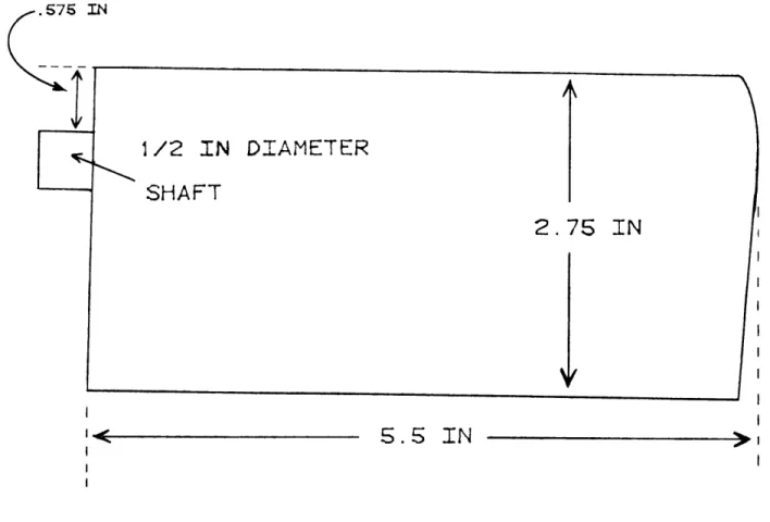
In determining the thickness of the stator blades, several factors needed to be addressed. These included adequate strength for minimizing tip deflections under load, cavitation, and form drag. For adequate strength, it was decided to construct the stator model from high tensile strength, heat treated aluminum (6061, T6). The resulting blade design had a one-half inch diameter circular shaft extending into the hub for attachment by clamping action. Beam theory was used to estimate the minimum shaft dimensions to withstand the anticipated forces during experimentation. This calculation eliminated the possible use of blades with thickness ratios less than ten percent at the hub. Thin blades minimize form drag, but thickness helps make the foil less sensitive to cavitation at increasing angles of attack. The result was a foil shape with a tapering thickness from hub to tip. The blade, 5.5 inches in span, was designed to be thirteen percent thick at the hub, and ten percent thick at the tip, with linear tapering in between. In fabricating the stator model, a constraint on the cutting tool capabilities resulted in a slight
thickening of the blade at the hub. From a hydrodynamic viewpoint, this was deemed insignificant due to the fact that the inflow would already disturbed by the stator hub assembly at this location.
3.2.2 Axial Separation Distance of Components
The axial separation of the stator and propeller as input into PLL required some interpretation. This was due to the fact that PLL is based on lifting line representations of the stator and the propeller. The logical reference point from which to assume a lifting line and measure this separation was the quarter-chord location for both components. The quarter-chord location is the point at which the lift force acts. The selection of a 4.5 inch separation distance was the result of numerous program runs of PLL and information contained in Hecker's report [6]. The water tunnel arrangement for mounting the stator ahead of the propeller on the propeller drive housing also placed a lower limit on this separation distance. As the separation distance between the components increased, the local radial coefficients of lift, required to produce the necessary circulation, also increased.
To summarize, the resulting stator design was machined from high tensile strength aluminum. It had nine blades and was 1.2 feet in diameter. The chord lengths were constant at 2.75 inches with a smooth rounded tip. The blade foil was uncambered. The thickness tapered linerly from a thickness ratio of thirteen percent at the hub to ten percent at the tip. The axial separation of the stator from the propeller was set at 4.5 inches. Each stator blade was clamped about a circular shaft into the hub assembly. This allowed for the adjustment of individual blades to any angle of attack. See Figure 3-3 for details on the hub assembly and Figure 3-4 for details on the stator blades. A photograph of the stator mounted on the drive shaft housing is included in Appendix 2.
ALUMINUM
i .020 IN SII
1.3 IN7.
0
IN
3. 625 IN > <2- 2.075 IN-->
I<.575 IN
S5 IN
1/2 IN DIAMETER CIRCULAR SHAFT
2. 7
IN
Figure 3-4: Stator Blade
Chapter 4
DESCRIPTION OF EXPERIMENTAL FACILITY
The experiment was conducted at the MIT Marine Hydrodynamics Laboratory (MHL). The lab features a variable pressure water tunnel. Water velocities of up to thirty feet per second can be generated. There are plexiglass windows in the tunnel test section which is 20 inches square by 55 inches long. A removable propeller drive shaft extends from upstream into the test section. The outside housing of the shaft does not rotate. Fluid flow is symmetric about the shaft.
Along side the tunnel, a two component laser doppler anemometer (LDA) system is in place. The LDA system is used for measuring local vertical and horizontal velocities in the test section. The laser is a Lexel, model 95, argon ion laser rated at 2 watts of power. The laser operates in conjunction with a photodector, a signal tracker, and a signal processor which ultimately convert particle velocities in the fluid to a proportional voltage signal. Further operational theory of LDA system functions will not be discussed, but clarification of how such systems operate can be found in Reference [19].
The laser is mounted on a motordriven transverse table system with digital position readout. Repeatability of positioning of the laser table is 0.0001 inches. Minimum movement of the table is also 0.0001 inches. The laser can be positioned by either a handheld remote control or by computer. A minicomputer system is
Chapter 5
DESIGN OF THE EXPERIMENT
5.1 Scope of the Experiment
The scope of the experiment was defined to study several of the theoretical models upon which the MIT MHL computer codes are based. The primary goal was to validate the computer predicted wake of the stator in the non-axisymmetric alignment by comparison with experimental velocity measurements.
The hub vortex generated by a propeller is of a Rankine vortex structure [18]. The stator, when operating in the tunnel by itself, generates a highly visible hub vortex cavity. These two vortices should tend to counteract each other when the stator is mounted ahead of the propeller. The effect should manifest itself in some cancellation of the strength of the hub vortex. This phenomena was studied and the results are discussed in Chapter 6.
Also performed in the course of the experiment were open-water tests for the 4497 propeller and for the stator/propeller combination. These tests provided the data necessary for the comparison of the propulsive efficiencies of the propulsors. The method of comparison requires some interpretation as there can be some justification for analysis at numerous operating points. It was decided that the fairest comparison would be at a point where an equal amount of thrust was provided.
The LDA system was used to collect velocity measurements to verify the non-dimensional circulation distributions for the stator blades for comparison with the numerical SSF-1 solutions. This was done in both the axisymmetric and
non-axisymmetric blade alignments. This check would ensure that the stator circulation input into PLL was actually the distribution on the blade. Additionally, the LDA system was used to map the flow field velocities in the plane of the propeller at several radii. Tangential and axial velocities were obtained for both the axisymmetric and non-axisymmetric blade alignments. This information was required for comparison with the PLL wake inflow predictions at the plane of the propeller.
5.2 Modeling Inclined Flow
As proposed in Chapter 1, the basis of the experiment is to design a stator which will favorably alter inflow to a propeller operating in an inclined flow. In formulating the approach to this experiment, it was recognized that the situation being addressed by this thesis could not be exactly modeled with the facilities in the lab. It is not possible to conduct an experiment with the propeller shaft inclined to the fluid flow in the MIT MHL water tunnel. Only axial flow can be obtained about the stationary shaft to which the stator was to be mounted. It was determined that a valid experiment could still be conducted.
By not inclining the flow, a predictable effect in the anticipated inflow wake can be taken into account. The once per revolution tangential velocity fluctuation is not actually present in the axial flow. Therefore, validation of the design and the code is accomplished by obtaining results which, when superimposed with the
absent tangential periodic variation, yield the PLL wake prediction for the actual
condition of inclined flow. Refer to Figure 5-1 to observe the anticipated experimental results for tangential wake in the plane of the propeller. Testing was done in both an axisymmetric and non-axisymmetric stator blade alignment. Discussion of the results is contained in Chapter 6.
- %. I '4 o I I 40 -D F / / I, I I 160 EGREES MEASURED IN PROPELLER DISK
Figure 5-1: Desired Test Results
5.3 The Stator Model
The resulting stator design is shown in photographs in Appendix 2 and the figures of Chapter 3. A diagram of the stator mounted in the tunnel is also shown in Figure 5-2. Also indicated in this figure are the approximate radii in the plane of the propeller where the velocity measurements were obtained, where the velocity measurements were obtained. The nine identical stator blades each had a one-half inch diameter circular shaft at the hub. Once set to the desired angle, the blade was clamped in the hub assembly about the circular shaft. This controllable pitch feature allowed the angle of attack of each blade to be set individually as required for the non-axisymmetric analysis. The entire stator, blades and hub assembly, V i g. V free 240 360 I I I I
were black anodized. Set location on the shaft.
screws were used to fix the hub assembly at the desired
RADII DISK PROPELLER DRIVE HOUSING
z~z~zi
IN PROPELLER STATOR TUNNEL WALL7777/
Figure 5-2: Stator Mounted in Water Tunnel
In order to measure the tangential velocities in the plane of the propeller for all stator blades, it was necessary to rotate the stator nine times during the course of the experiment. This repositioning was necessary to point the tip of the blade being measured directly at the laser. Tangential velocity measurements were made at selected radii in a forty degree sector on each stator blade, twenty degrees on either side of the blade's tip.
5.4 Operating Conditions
It was logically assumed to design the stator for use with the propeller at its design operating condition. This lead to the immediate establishment of some operating variables. The design advance coefficient, J , of the 4497 propeller is 0.889, which at a selected 1200 rpm establishes the water tunnel velocity at 17.72 feet per second. The thrust coefficient, KT, is nearly 0.23 at design J, which
provides a thrust of approximately 180 pounds. The water tunnel velocity and the required thrust were also inputs to PLL in earlier computer runs.
Chapter 6
EXPERIMENTAL RESULTS
6.1 Hub Vortex Strength
As mentioned in Chapter 5, there were several objectives of the experiment. These were to be accomplished in addition to the primary task of designing a stator which would modify the inflow in the plane of the propeller to counteract a shaft angle.
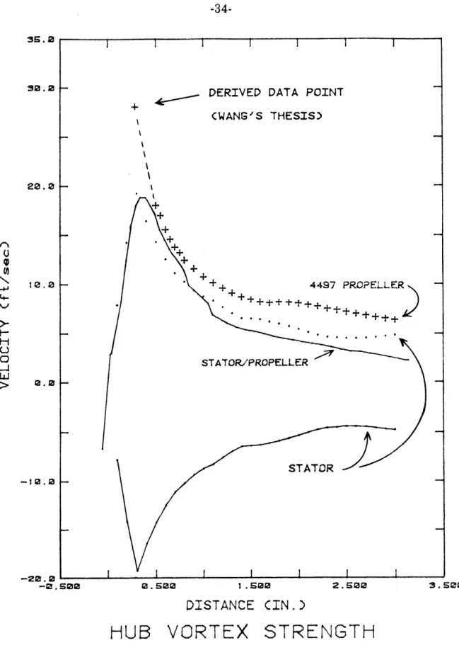
The first portion of the experiment dealt with the stator in an axisymmetric configuration, all nine blades set at the same angle of attack. As shown in the graph of Figure 3-1, the circulation distribution from SSF-1 was approximately equal to the PLL circulation when the angle of attack was thirteen degrees. With the stator model mounted in the water tunnel by itself at the operating speed of 17.72 feet per second, a significant hub vortex cavity was visible. See Appendix 2, still photograph No. 2 to note its appearance. The LDA system was used to collect tangential velocity measurements for the hub vortex at a distance one inch downstream from the apex of the tip of the hub. This location was selected for study as it was observed that the vortex position was very stable at this point. Velocity measurements were obtained beginning at a position three inches horizontally from centerline of the axis of the shaft inward to the point at which the laser signal was lost due to the hub vortex cavity. This data is presented in the graph of Figure 6-1. The sign of these velocity measurements was changed and plotted a second time to provide for easier comparison with the magnitude of other velocity measurements. Similar measurements at the same location were made for
the 4497 propeller operating by itself. The propeller hub vortex was similar in visual appearance to the stator hub vortex, and, as it should be, its direction of rotation was reversed. See Appendix 2, still photograph No.3 to note its
appearance.
Lastly, the hub vortex velocity measurements for the stator and propeller combination were obtained. Its direction of rotation was the same as that of the propeller's hub vortex. In this configuration, at a water tunnel speed of 17.72 feet per second and the propeller at 1200 rpm, the hub vortex was not visible. These curves are also plotted and labelled in Figure 6-1. The peak value of tangential velocity was definitely obtained for the stator operating alone and for the stator/propeller combination. This statement is made based on the data points which shape these curves just inward from the peak. These points attest to the Rankine vortex nature of the hub vortex. The Rankine vortex is discussed further in Wang's doctoral thesis [18]. It is strongly suspected that the peak value of the curve for the 4497 propeller hub vortex was not obtained due to the loss of the LDA signal when the measuring volume was moved just adjacent to the hub vortex cavity. Referencing Wang's thesis, an approximation was made for the the magnitude of the peak tangential velocity and for the radius of the hub vortex. It is recognized that Wang experimented with a slightly different propeller at a lower advance coefficient, however, extrapolation of his data does provide a reasonable analytical approximation. It was estimated that the peak tangential velocity, if able to be measured, would be nearly 28 feet per second and its radius would be approximately 0.28 inches. Further justification for this value is derived from the fact that it was visually observed that the laser signal was lost at a location adjacent to the hub vortex cavity. This was at a radius greater than 0.6 inches. In view of Wang's experimentation, this radius seems too large to be the actual hub
DERIVED DATA POINT (WANG'S THESIS) 4497 PROPELLER STATOR 0.502 1.502 2.50 DISTANCE CIN.)
HUB VORTEX STRENGTH
Figure 6-1: Hub Vortex Comparisons 3S.0 30.0 I-± 2.2 F--12.0 --20 . 0 -0.5 ;oo 3.500 1 1 1 1 I I I 1 1
vortex radius. It is highly probable that the cavity was enlarged due to entrained air. The conclusion is that the peak tangential velocity must be greater than the last measurement obtained and must be located closer to the centerline. This derived data point was later plotted and labelled on the graph of Figure 6-1.
The data shows a partial cancellation of the strength of the peak value of the hub vortex for the stator and the propeller operating together. This result was anticipated based on theoretical considerations, and on the absence of any visible vortex cavity during this phase of the experiment. See Appendix 2, still photograph No.4 which documents this phenomena.
6.2 Axisymmetric Testing
6.2.1 Non-Dimensional Circulation Measurements
The angle of attack which provided the desired circulation distribution for the stator blades in the axisymmetric case was determined to be + 13 degrees relative to the inflow. To ensure that the circulation distribution on the stator blades was as predicted by the SSF-1 analysis program, velocity measurements were made around a stator blade a several radii. These measurements were made around rectangular closed contours at numerous discrete location. These velocities were converted to a non-dimensional circulation consistent with the manner used in the computer programs to allow for comparison. The distribution of the experimental non-dimensional circulation is graphed and presented in Figure 6-2 with the SSF-1 predicted distribution. Thickness effects were accounted for in the SSF-1 distribution. The comparison is excellent with respect to the shape of the distribution, but is in disagreement by approximately 7 percent in magnitude. The experimental data was greater. One possible explanation for the experimental
EXPERIMENTAL DATA
PLL
SSF-1 0 0. 00 r/RAXISYMMETRIC
CIRCULATION
Figure 6-2: Experimental & Axisymmetric Circulation
0.a16
0.20.
1 . a
I I I
circulation being greater is the tunnel wall effect experienced in the test section. The presence of the tunnel wall restricts the flow in the test section and could thereby result in more circulation on the blade than would otherwise be present in an unrestricted flow. Additional deviation could be introduced by not setting the stator blade angles accurately. It is estimated that the bench technique for setting blade angles is accurate to within one-half degree. A circulation distribution from the SSF-1 program for an angle setting of + 13.5 degrees was obtained. This was done to better establish the magnitude of error which could be introduced by inaccurate setting of the blade's angle of attack. The results of this program run are plotted in Figure 6-3 along with experimental data and the circulation distribution for the + 13 degree angle of attack. Assuming that the angle of attack was set one-half degree greater than desired, the graph shows the experimental data to be in much closer agreement with the computer prediction.
It can therefore be concluded that the SSF-1 program is a reliable tool for predicting circulation distributions. This would again be demonstrated in the non-axisymmetric stator testing.
6.2.2 Flow Field Measurements
With the stator blades in an axisymmetric alignment, axial and tangential velocity measurements were made at several radii in the plane of the propeller. Figure 6-4 displays the tangential velocities at five different radii, 4.5 inches downstream from the quarter-chord location of the stator blades. The shape of these curves was as anticipated and can be logically explained. Referring to Figure 6-5 assists in visualizing the flow situation. At the smallest radius, the major fluctuation is due to the hub vortex effects. At the outer radii, the large fluctuation is due to the proximity of the tip vortex. This is also true for r/R = 0.8. At the
EXPERIMENTAL DATA 13.S DEGREE ANGLE OF ATTACK I SSF-1 13 DEGREE ANGLE OF ATTACK 0. 60 I .0 r/R
AXISYMMETRIC CIRCULATION
Figure 6-3: Circulation Distribution Comparison 0.006
0 0. 2ae
0.000 -fl 0 (0 O C.- -4. 9002 -0802 - L r -622 -2. -16.0 -5.0 6.0 Theta
CDegrees)
TANGENTIAL WAKE
Figure 6-4: Tangential Wake - Axisymmetric Stator
t"/R=e. 8 I / I I / I
i t
/
I I' STATOR BLADENa
I r/R=O0. 4 I / HUB VORTEX TIP VORTEX r/R=. r/R=0.25Figure 6-5: Radial Locations for Velocity Measurements
radii near mid-span, the tangential velocity fluctuation is not as pronounced due to the distance from both the tip vortex and the hub vortex. The modest negative (downward) velocity at these radii is due to the flow being inclined by the thirteen degree angle of attack of the blades.
6.3 Non-Axisymmetric Testing
6.3.1 Non-Dimensional Circulation Measurements
In the non-axisymmetric testing of the stator, the nine blades were set at angles of attack determined from the SSF-1 program. Numbering the nine blades consecutively around the stator, the angles were as follows: 19.0 degrees for blade 1,
16.1 degrees for blades 2 and 9, 11.0 degrees for blades 3 and 8, 7.0 degrees for blades 4 and 7, and 5.5 degrees for blades 5 and 6. As shown in Figure 3-2, these
X
angles gave the best match to the PLL circulation distributions which produced the desired predicted tangential velocities. As was done in the axisymmetric case, non-dimensional circulation measurements were obtained. Based on the reliability of the SSF-1 program established in earlier testing, only three radii on two blades were selected for circulation measurements. The most heavily and lightly loaded blades were sampled at radii about the location the maximum circulation was anticipated to occur. This experimental data is plotted for comparison with the SSF-1 program distribution in Figure 6-6.
Only five blade circulation distributions are shown in the graph because blades 6,7,8, and 9 are symmetric with blades 5,4,3, and 2 respectively. The circulation distributions for the symmetric blades are essentially the same. For the most heavily loaded blade, a similar experimental result to the axisymmetric circulation measurement is noted. With only three data points to compare, it would be suspect to generalize about the shape of the entire distribution. However, with the previous axisymmetric results as a basis, it is claimed that the shape of the distribution matches very well to the SSF-1 program prediction. The magnitude is in disagreement by approximately 8 percent. The same justifications stated for the axisymmetric discrepancies between experimental and computer predicted circulation apply here as well. For blade 5, the most lightly loaded blade, the experimental results are nearly identical for two of the three radii sampled. The shape of the circulation distribution for the lightly loaded blades, which are set at small angles of attack, is more heavily influenced by the blade twist.
Based on these experimental results, it is claimed that the circulation distributions predicted by the SSF-1 program are very nearly the actual distributions on the stator blades. This validation was necessary prior to proceeding to the flow field measurements in the plane of the propeller for the
non-EXPERIMENTAL DATA
EXPERIMENTAL DATA
0.6s0
NON-AXISYMMETRIC
CIRCULATION
Figure 6-6: Experimental & Non-Axisymmetric Circulation 0.030 0. 828
-SSF-1
0.010 -0.000 -0.0.12 1.000 i 1 1 soaxisymmetric stator. The mapping of these tangential velocities is the key indicator for comparison to PLL wake predictions and the basis for judging the success of the design. The induced tangential velocities represent solid evidence that the stator is providing the desired modification to the inflow.
The non-axisymmetric circulation distributions provided by the SSF-1 program were used to supply inputs back into PLL for revised wake predictions. This was done to allow for the fact that the circulation distributions on the stator blades in the non-axisymmetric alignment were not exactly those originally used by the PLL program. The matching procedure between the PLL and SSF-1 programs discussed in Chapter 3 resulted in some differences in circulation when the 3-dimensional effects were considered. In order to perform a more accurate comparison between the computer wake prediction and the experimentally obtained data, this iteration was performed. Figure 6-10 presents this revised wake prediction.
6.3.2 Non-Axisymmetric Flow Field Measurements
The mapping of the velocity measurements in the plane of the propeller for the non-axisymmetric case was done at three different radii. The experimental results for the tangential velocity measurements are presented in Figure 6-7, Figure 6-8, and Figure 6-9.
As shown in Figure 5-1, the overall desired experimental result for the shape of the tangential wake is periodic for one revolution about the disk of the propeller. This is due to the absence of inclined flow in the tunnel. The superposition of a once per revolution tangential velocity fluctuation due to inclined flow upon the experimental tangential flow mapping should produce the wake predicted by PLL. These wake predictions from PLL were presented in Figure 2-2 and the revised wake
88.0 160.0 240.2
Thet.a (Degrees)
TANGENTIAL
WAKE
Cr/R
Figure 6-7: Tangential Wake, r/R = .45 0.00 C 0 -0 .25 0.0 320.0 360.0
=
.45)
_ __ 1 1 1 I *o.. 'I240.0
Theta (Degrees)
TANGENTIAL
WAKE
Cr/R
Figure 6-8: Tangential Wake, r/R = .60 2.000 0 0 L...~ 162 C 0 -JJ -2. 250 -2 . 350 0.2 80.0 162.20 320.2 360.2
=
.
60)
_ I 1 I 1160.0
Theta (Degrees)
TANGENTIAL
WAKE
(r/R
Figure 6-9: Tangential Wake, r/R = .75.3 0. 000 q) -0. 3s0 0.0 80.0 240.0 320.0 360.0
=
.
75)
_ I 1 1':; r :
.. Cis shown in Figure 6-10. Some overlap of the data points exists on the graphs due to sampling about 24 degrees on either side of each stator blade. This was done intentionally to assist in bringing the nine data files together on one graph. It should be noted that some measurement error due to positioning was undoubtedly introduced each time one of the nine blade tips was directed at the laser by rotating the entire stator assembly on the shaft housing.
From the graphs, the amplitude of the ratio of the tangential velocity to the free stream velocity about its mean is approximately 0.10. The assumed shaft angle for producing the inclined flow was seven degrees for purposes of this experiment. The amplitude of the tangential velocity fluctuation due to a seven degree shaft angle is 0.12. This represents a favorable comparison. Figure 6-10 shows the PLL wake prediction when the SSF-1 program results for non-axisymmetric analysis are used to supply input back to the PLL program. This would be the wake pattern if the experimental results were superimposed upon the inclined flow harmonic fluctuation in tangential velocity. Note that the data for tangential wake inflow does roughly capture the nine smaller amplitude periodic oscillations which represent the influence of the nine stator blades. This effect is best seen in Figure 6-9. This effect was part of the PLL wake prediction, especially at the outer radii. The general observation, which is supported by graphical presentations of experimental data, is that the non-axisymmetric stator does induce tangential velocities to counter the inclined flow. It can be concluded that the stator in this non-axisymmetric alignment, when placed in 7 degree inclined flow, would have a tangential wake as predicted by PLL in Figure 6-10.
During the non-axisymmetric testing, axial and tangential velocity measurements were taken at various radii in the plane of the propeller. These measurements indicate that the flow was indeed inclined by the non-axisymmetric
r 9 . 227 TANGENTIAL WAKE IN __ _ I _ _ _ PROPELLER DISK -. 0.26 lI-awese " - I I 1 - . % % % o rc. r-10. 44 ~~- ft%- -% % 0 -a a eI I I I I I e . e . 1 I I I e-3 44 t -.. s , I I I I I . os44 I I I I .I247 2.000 129.0 240.2 360.0
stator. The angle of inclination did vary with radius. The flow inclination is easily observed by referring to Appendix 2, photographs No.5 and No.6.
6.4 Propulsive Efficiency
In order to compare the efficiency of the propeller to the stator/propeller combination, standard open-water tests were performed in the water tunnel. Programs were available in the MIT MHL for conducting these tests. The 4497 propeller was tested several times to ensure that a reliable test result was obtained. The representative output from one of these open-water tests in included in Appendix 3. At the design advance coefficient, J, of .889, the thrust coefficient, KT
was .233. At 1200 RPM the thrust provided is 180.0 pounds. Its propulsive efficiency, 1, was 0.65 at design J. Figure 6-11 graphically displays the results of this open-water test. Appendix 1 contains a PLL output for the propeller operating by itself. The I value numerically predicted was by PLL was 0.67. The slight discrepancy is most likely accounted for by some difference between the propeller circulation distribution input to PLL and the actual distribution on the blades.
After mounting the stator model on the propeller drive housing just forward of the 4497 propeller, more open-water tests were conducted. The stator was positioned on the housing such that the quarter chord location of the stator was 4.5 inches forward of the quarter chord location of the propeller. A representative result from one of these tests is included in Appendix 3. Figure 6-12 graphically displays the results of this test. Before comparing these results with the results for the propeller alone, the increased drag on the propulsor combination due to the stator must be taken into account. More water tunnel tests were conducted to determine the drag on the stator. A testing sequence was devised whereby the drag on the stator, minus any hub vortex effects, was estimated over a range of
1.20-
4497 PROP
4ITHOUT S
1 .00-Kq
0 t E 0 ' 0.60u
EK:
0* - 0.40 0.20-0.40 0.60 0.80 1.00 Advance Coefficient, J = V/nDFigure 6-11: Propeller 4497 Open-Water Test
ELLER
TATOR
1.20
1.20
4497 PROP
WITH STA
1.e00
Kq
Et
a0.20--hl U C.*
K
6 0.00 0.40 0.60 0.80 1.00 1.20 Advance Coefficient, J = V/nD'ELLER
TOR
a
1.40operating speeds. The influence of the hub vortex was experimentally estimated at 2.2 pounds at the operating speed of 17.72 feet per second. This correction was applied to the experimentally derived value of 15.3 pounds of drag on the stator with hub vortex. Therefore, the drag due to the stator alone was estimated at 13.1 pounds. This value compares remarkably well with the PLL prediction of 11 pounds of drag. The experimental value is substantially verified by the computer result.
Having established a reliable estimate for the stator drag, the propulsive efficiencies of the propeller and the stator/propeller can now be compared. To perform a fair comparison, it was decided to select operating points where both propulsors were providing an equal amount of thrust. At the J value of 0.89, the 4497 propeller provided 180 pounds of thrust. The KT at this point was 0.233. The propulsive efficiency, 1, was 0.65. This information is also graphically presented in Figure 6-13, which presents the open-water test results for the propeller operating with and without the stator. Also plotted for the propeller is the curve of constant Kr /J2, a ratio which relates to the thrust loading coefficient, CT. Basically, the KT/J2 curve represents the operating points where an equal amount of thrust is provided.
To locate the appropriate stator/propeller operating point for comparison of efficiency, it was first necessary to account for the reduced thrust due to drag on the stator. The operating point selected would have to represent approximately 193 pounds of thrust to offset the estimated 13.1 pounds of stator drag at the water speed of 17.72 feet per second. Through a trial and error procedure, numerous operating points were selected and analyzed. This lead to the determination of a comparison operating point at J equal to 1.01. At this J, the thrust loading coefficient, CT, was .636 and when corrected for stator drag, a thrust of 180.1
1 . 20 IN CN 4:' 0.860 .40 N N N N cN JJST 'h- 0 .80-C S'97 = 0.65 0 "' O.6 . /ADJUSTED_ SKT CURVE 0 .20- t KT/J l " -0.00 0.00 0.20 0.40 0.60 Advance Coeffi 0.80 1.00 1.20 1.40 1.60 cient, J = V/nD
pounds is anticipated. The KT/J2 ratio was equal to 0.31795 and Kr was 0.324.
Therefore, assuming that the operating speed is fixed at 17.72 feet per second, the thrust provided at this operating point would be 192.9 pounds. Correcting for stator drag results in a net thrust of approximately 180 pounds. The calculated propulsive efficiency, I = KTJ/2 KQ, at this point is 0.73. This indicates an 8
percent increase in I even after accounting for stator drag.
The curves of Figure 6-13 for the stator/propeller are not corrected for drag due to the stator. The K curve would be shifted downward to adjust for the reduced thrust. A portion of the corrected KT, in the vicinity of the comparison operating point is plotted on Figure 6-13. Also, the propulsive efficiency curve would be slightly reduced in amplitude to reflect this correction.
Chapter 7
CONCLUSIONS
7.1 Experimental Summary
This experimental thesis effort was designed to address a propulsive problem associated with a propeller operating on an inclined shaft. This is the case for a large majority of surface ships of all sizes. The objective was to design a stator model which would minimize the once per revolution tangential wake harmonic associated with inclined flow. The primary benefit of achieving this modified inflow would be an increase in propulsive efficiency. A validation of the PLL computer wake predictions was performed by a comparison with experimental flow field measurements.
The results of the experiment support the claim that the stator improves the propeller's performance. When the two component propulsor was tested with the stator in an axisymmetric blade alignment, there was a significant increase in the propulsive efficiency when compared to the propeller operating alone. This was indicated by the results of the open-water tests. This increase was approximately 8 percent at an operating point where an equal amount of thrust was provided.
The focus of the non-axisymmetric testing was to incline the flow and to map the flow field velocities in the plane of the propeller. The results validate the computer generated wake predictions of the PLL program. The non-axisymmetric
stator induced tangential velocities which tended to minimize the once per revolution harmonic due to shaft angle. While unable to model inclined flow, superposition of this harmonic fluctuation on the flow field mapping obtained did
produce the desired result. It is reasonable to conclude that the propulsive efficiency of the non-axisymmetric stator and propeller in an inclined flow would be
greater than that of the propeller alone.
During the course of the experiment, the experimentally obtained non-dimensional circulation distributions were used to check the accuracy of the output of the recently developed MIT MHL SSF-1 program. The experimental data collected in this portion of the testing generally exceeded the computer prediction by 7 to 8 percent. However, there appeared to be excellent agreement with regard to the shape of the distribution.
The additional testing performed with reference to the hub vortex strength supports the following statements. The cancellation effect concerning the hub vortices of the stator and the propeller does not represent a significant gain in terms of thrust and efficiency. It was observed that the cancellation effect is not complete at operating points where a reasonable amount of thrust is provided. The negative thrust caused by the hub vortex is not significant in comparison to the net thrust. The results of velocity measurements of hub vortex strength for the stator, the propeller, and the combination support the concept of the Rankine vortex as a model for the hub vortex.
7.2 Discussion
Upon reflection of the results obtained from this experiment, some logical extensions for further testing of the stator can be identified. It was noted that the combination of the stator/propeller was more efficient than the propeller alone. A testing scheme could be devised whereby open-water tests with the axisymmetric stator and propeller would be performed. Successive tests could be conducted
varying the angle at which the stator blades are set. The objective would be to determine the optimum angle in terms of achieving the highest propulsive efficiency while providing an equal amount of thrust as the propeller operating alone. The existing computer programs could be exercised to conduct the same experiment to arrive at the analytical answer. A favorable comparison between the determined angles should result.
The number of dimensional circulation data points obtained in the non-axisymmetric testing was limited. This was felt to be justified in this experiment by the reliability established during more extensive axisymmetric sampling. However, the collection of more data would provide greater confidence to the output provide by the SSF-1 analysis program.
The general conclusion which can be drawn from this effort is that the non-axisymmetric stator can be used to favorably modify propeller inflow to counteract the effects of shaft angle. Increased propulsive efficiency can be achieved by a stator by reducing the energy left in the propeller's wake. It is recognized that these results were produced in the laboratory, and that extension of this concept to operating ships presents a greater challenge.