Design & Implementation of a Wireless Sensor
Prototyping Kit
by
Jamison Roger Hope
S.B., 2004
Submitted to the Department of Electrical Engineering
and Computer Science
in partial fulfillment of the requirements for the degree of
Master of Engineering in Electrical Engineering and Computer Science
at the
MASSACHUSETTS INSTITUTE OF TECHNOLOGY
May 2005
[Jhe
acC
7
©
Massachusetts Institute of Technology 2005. All rights reserved.
.jpartment
of Electrical Engineering and
f
Computer Science
May 19, 2005
Certified by. ...
.. .
...
...
Ruaidhri M. O'Connor
Assistant Professor
}~es
Supervisor
Accepted by ...
Arthur C. Smith
Chairman, Department Committee on Graduate Students
Author.
MASSACHUSETTS INSTITUTE OF TECHNOLOGY
J UL
18
2005
....
LIBRARIES..-.
Design & Implementation of a Wireless Sensor
Prototyping Kit
by
Jamison Roger Hope
Submitted to the Department of Electrical Engineering and Computer Science on May 19, 2005, in partial fulfillment of the
requirements for the degree of
Master of Engineering in Electrical Engineering and Computer Science
Abstract
In recent years, wireless sensor networks (WSN) has become an active area of research among computer scientists. In this work, JONA, a prototyping kit for wireles sensors, will be described. The intention of this kit is to open WSN research to interested parties outside of the electrical engineering and computer science communities, who may wish to use wireless sensor networks in their own work. The kit's hardware and software are based upon de facto standards for academic research (Crossbow and TinyOS), with an emphasis on low cost and ease of development. This research has the dual goals of describing a classroom kit and developing a self-contained document providing background material suitable for an introductory project-based class on WSN.
Thesis Supervisor: Ruaidhri M. O'Connor Title: Assistant Professor
.4004"" --- --- -- --* -" -ljj*,- --. , -11-1- -Ai I M.-I
Acknowledgments
First of all, I would like to thank Prof. Ruaidhri M. O'Connor for agreeing to super-vise this thesis and for allowing me this opportunity to learn about wireless sensor networks. Your guidance and patience have been indispensable throughout this en-deavor.
I would also like to thank Dr. Nathaniel Osgood, who has consistently made the
dreary, windowless basement of Building 1 a fun place to work. Your enthusiasm has been an inspiration, and your assistance has proven invaluable time and again.
I must also express my appreciation of the MIT Technology and Development
Pro-gram and its partnership with the Malaysia University of Science and Technology, which provided me with financial support for this school year, releasing my parents
from a great burden they carried faithfully for my four years as an undergraduate.
My mom, Karen Hope. You were my first teacher, and I can always count on you
for wise counsel. You've always encouraged me to do my best while maintaining a balance in my life. Most importantly, you taught me to put my trust in God. Happy
birthday!
My dad, Bill Hope. You supported my scholastic education, but you also taught me
and showed me lots of stuff that you don't learn about in school, especially about fish and wildlife. Thanks for showing me why Florida's such a great and unique place to be. You also taught me a lot about buildings and engines and all sorts of physical systems like that. Any knack I now have for engineering has its roots in that.
My cousin, Isaac Benjamin. You remind me that the world isn't always as complicated
as the grown-ups make it seem, and you show me what it means to have faith like a child. Always remember that Jesus loves you, even when you make mistakes. And if the Creator of the Universe knows you and loves you, then who cares what anybody else thinks?
The rest of my family. You've always done nothing but offer me continuous moral and financial support. Any accomplishments I've realized have only been possible because of you.
My friends, some of whom I've known just in these past five years, others more
than half my life. Thank you all for always encouraging me and making sure that I remember that life "es muy divertirse." I truly do get by with a little help from my friends.
Saving the best for last, my Lord and Savior, Jesus Christ, without whom I would not be here. What a relief it is to know that I don't have to worry about anything, that, no matter what, God loves me and will take care of me! Here are some most-excellent Bible verses:
Jesus Christ our Lord. Romans 6:23, KJV
Trust in the LORD with all thine heart; and lean not unto thine own understanding. In all thy ways acknowledge him, and he shall direct thy paths. Proverbs 3:5-6, KJV
Every good and perfect gift is from above, coming down from the Fa-ther of the heavenly lights, who does not change like shifting shadows.
James 1:17, NIV
This is the confidence we have in approaching God: that if we ask any-thing according to his will, he hears us. And if we know that he hears us-whatever we ask-we know that we have what we asked of him.
1 John 5:14-15, NIV
Do not be anxious about anything, but in everything, by prayer and pe-tition, with thanksgiving, present your requests to God. Philippians 4:6,
NIV
Commit to the LORD whatever you do, and your plans will succeed.
Proverbs 16:3, NIV
Cast your cares on the LORD and he will sustain you; he will never let the righteous fall. Psalm 55:22, NIV
"Therefore I tell you, do not worry about your life, what you will eat or drink; or about your body, what you will wear. Is not life more important than food, and the body more important than clothes? Look at the birds of the air; they do not sow or reap or store away in barns, and yet your heavenly Father feeds them. Are you not much more valuable than they? Who of you by worrying can add a single hour to his life?
"And why do you worry about clothes? See how the lilies of the field grow. They do not labor or spin. Yet I tell you that not even Solomon in all his splendor was dressed like one of these. If that is how God clothes the grass of the field, which is here today and tomorrow is thrown into the fire, will he not much more clothe you, 0 you of little faith? So do not worry, saying, 'What shall we eat?' or 'What shall we drink?' or 'What shall we wear?' For the pagans run after all these things, and your heavenly Father knows that you need them. But seek first his kingdom and his righteousness, and all these things will be given to you as well. Therefore, do not worry about tomorrow, for tomorrow will worry about itself. Each day has enough trouble of its own." Matthew 6:25-34, NIV
How awesome is that? A Heavenly mandate to relax. Dude, you rock, God.
And now, I guess it's time for me to demonstrate that, as Dilbert says, "there's nothing wrong with my verbal skills; it only seems that way because my math skills are so high."
Contents
1 Introduction
1.1 Wireless Sensor Networks . . . . 1.2 Current Research and WSN Implementations
1.2.1 Berkeley, TinyOS and nesC . . . .
1.2.2 Habitat Monitoring on Great Duck Isla 1.2.3 Seismic Monitoring . . . . 1.2.4 The MIT pAMPS Project . . . .
1.2.5 Other Related Research . . . . 1.3 How to Read This Document . . . .
2 An Overview of Relevant Theory
2.1 Elementary Circuit Theory . . . .
2.1.1 Current . . . .
2.1.2 Voltage . . . .
2.1.3 Power . . . .
2.1.4 Resistance and Resistors . . . .
2.1.5 Capacitance and Capacitors . . . .
2.1.6 Inductance and Inductors . . . .
2.1.7 D iodes . . . .
2.1.8 Transistors . . . . 2.1.9 Operational Amplifiers . . . .
2.2 Microcontrollers and Their Parts . . . .
2.2.1 C PU . . . . 17 17 18 . . . . 18 nd 19 19 20 24 26 29 30 30 32 35 35 40 42 45 46 48 49 50
. . . .
. . . .
2.2.2 I/O Ports and Parallel Communications . . . . 53
2.2.3 Serial Communications Options . . . . 55
2.2.4 The Analog to Digital Converter (ADC) . . . . 58
2.3 Common Laboratory Equipment . . . . 59
2.3.1 M ultim eter . . . . 59
2.3.2 O scilloscope . . . . 60
2.4 Programming Languages & Source Code . . . . 60
2.4.1 Open Source Software . . . . 61
3 Motivation and Design Goals 63 3.1 Classroom Needs . . . . 63
3.1.1 1.961/CEM508 . . . . 64
3.1.2 Software Requirements . . . . 64
3.1.3 Hardware Requirements . . . . 65
3.2 D esign G oals . . . . 67
4 Implementation of the JONA Prototyping Kit 69 4.1 The JONA Hardware Platform . . . . 70
4.1.1 The PROBOmega128 Prototyping Board . . . . 70
4.1.2 The DR3000-1 Transceiver Module . . . . 73
4.1.3 The LedsArray . . . . 77
4.2 The JONA Software Platform . . . . 79
4.2.1 TinyOS Design . . . . 79
4.2.2 nesC D esign . . . . 81
4.2.3 H ello, W orld! . . . . 82
4.2.4 The JONA TinyOS platform directory . . . . 91
5 Deployment 107 5.1 LedsA rray . . . . 107
5.2 UART: Bidirectional Communication . . . . 115
5.4
5.5 5.6
5.3.1 Collecting & Transmitting Readings with
5.3.2 Receiving Readings with TOSBase . . .
5.3.3 Displaying Readings with Java . . . . Constructing an ADC Input . . . . Sensing Without the ADC . . . . Alternative Power Sources . . . .
5.6.1 The 9V Battery Adapter . . . .
5.6.2 Solar/RF Power Harvesting . . . .
OscilloscopeJonaRF
. . . .
. . . .
. . . .
. . . .
. . . .
. . . .
. . . .
6 Conclusion 6.1 H ardw are . . . . 6.2 Softw are . . . . 6.3 Final Thoughts . . . . A Common PrefixesB Bits, Binary and the Digital Abstraction
C The ASCII Encoding Scheme
D Semiconductors
E PROBOmega128 Schematic
F JONA Radio Module Schematic
G HelloWorld: A nesC/TinyOS Application Example G.1 HelloWorld.nc ... ...
G.2 HelloWorldM.nc. ... ... G.3 Makefile ... ...
H Additions Made to the Makerules File to Support JONA H.1 The Additions ... ... H.2 Makerules ... ... 121 127 127 127 130 141 141 143 145 145 146 147 149 151 153 157 161 163 165 165 165 167 169 169 175
I JONA Platform Directory Files 1.1 .platform 1.2 1.3 '.4 '.5 1.6
1.7
1.8 '.9 I.10 1.11 1.12 1.13 1.14 1.15 1.16 1.17 1.18 1.19 1.20 1.21 1.22 1.23 1.24 1.25 1.26 J Sample Applications J.1 KnightRider . . . accel.h . . . . Accel.nc . . . . AccelM.nc . . . . ADCC.nc . . . . ChannelMonC.nc . . hardware.h . . . . HPLADCM.nc . . . HPLPotC.nc . . . . . HPLSlavePinC.nc . . HPLUARTM.nc . . . IntToLed.nc . . . . . IntToLedM.nc . . . . IntToLedsArray.nc IntToLedsArrayM.nc Led.nc . . . . LedC.nc . . . . LedsArray.nc . . . . LedsArrayC.nc . . . LedsC.nc . . . . LedsM.nc . . . . photo.h . . . . Photo.nc . . . . PhotoM.nc . . . . RadioTimingC.nc . . SpiByteFifoC.nc . . .. .
185 185 185 186 187 188 188 191 193 195 196 197 198 198 199 200 201 203 204 206 208 209 210 211 212 213 213 217 217J.1.1 M akefile . . . . 217 J.1.2 KnightRider.nc . . . . 217 J.1.3 KnightRiderM .nc . . . . 218 J.2 TestUartSendReceive . . . . 219 J.2.1 M akefile . . . . 219 J.2.2 TestUartSendReceive.nc . . . . 219 J.2.3 TestUartSendReceiveM .nc . . . . 220 J.3 OscilloscopeJonaRF . . . . 220 J.3.1 M akefile . . . . 220 J.3.2 OscilloscopeJonaRF.nc . . . . 221 J.3.3 OscilloscopeJonaRFM .nc . . . . 221 J.3.4 OscopeMsg.h . . . . 225 J.4 HumiditySense . . . . 225 J.4.1 M akefile . . . . 225 J.4.2 HumiditySense.nc . . . . 226 J.4.3 HumiditySenseM .nc . . . . 226 K Software Licenses 229 K.1 Berkeley License . . . . 229 K.2 Intel License . . . . 229 K.3 M IT License . . . . 230 Bibliography 231 Index 235
List of Figures
1-1 Transmission radii in a wireless sensor network. . . . . 23
2-1 A simple application of KCL. . . . . 31
2-2 Another simple application of KCL. . . . . 32
2-3 Two Voltage Sources in Series . . . . 33
2-4 A simple KVL example. . . . . 34
2-5 O hm 's Law . . . . 36
2-6 Two Resistors in Series . . . . 36
2-7 Two Resistors in Parallel . . . . 37
2-8 Voltage D ivider . . . . 39
2-9 Two Capacitors in Series . . . . 40
2-10 Two Capacitors in Parallel . . . . 41
2-11 Two Inductors in Series . . . . 43
2-12 Two Inductors in Parallel . . . . 44
2-13 D iode . . . . 45
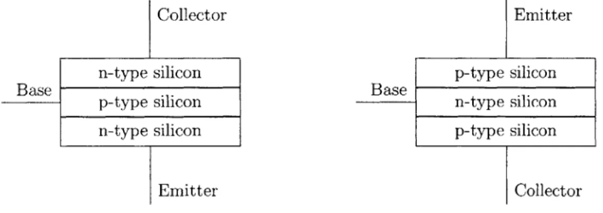
2-14 Bipolar Junction Transistors: npn (left) and pnp. . . . . 46
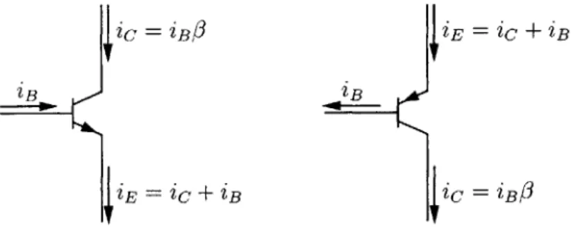
2-15 Circuit diagram BJTs-npn (left) and pnp-with currents labelled. 47 2-16 An op amp configured to be a voltage multiplier. . . . . 49
2-17 Block diagram of the ATmega128 [5]. . . . . 51
2-18 Closeup of the ATmega128 CPU, showing the ALU and registers [5]. 52 4-1 PROBOmega128 (Top side) [30]. . . . . 71
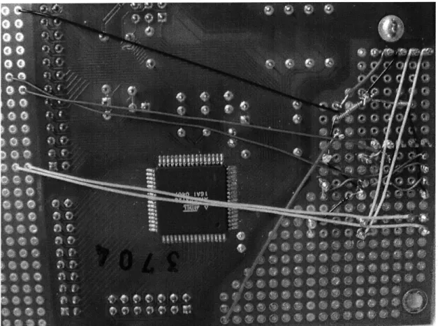
4-2 PROBOmegal28 (Bottom side) [30]. . . . . 71
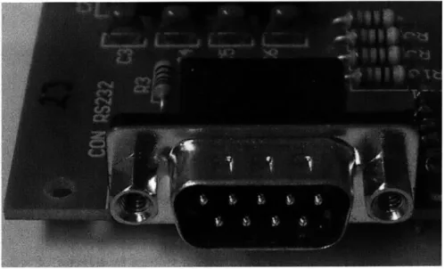
4-4 The serial port, labelled "CONRS232" 4-5 4-6 4-7 4-8 4-9 4-10 4-11 4-12 4-13 4-14
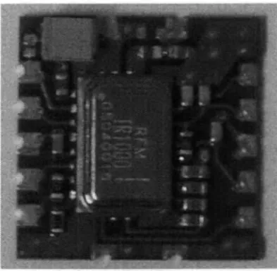
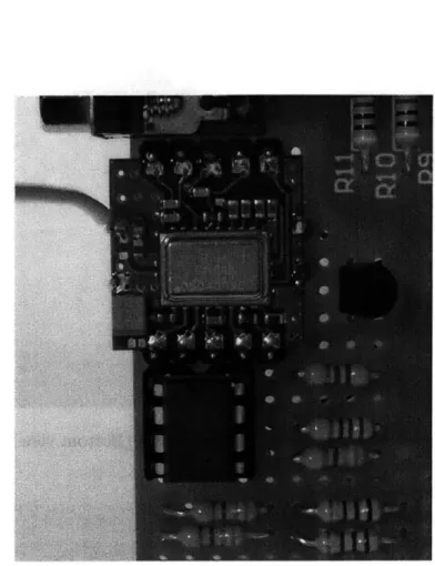
The DR3000-1 transceiver module... The DR3000-1 mounted (Top view). The DR3000-1 mounted (Bottom view). The DR3000-1 CONPIO connections. One LED of the LedsArray. . . . . The LedsArray (in Green). . . . . The HelloWorld string array. . . . .
A jumper cap. . . . . CON.ADC with a jumper cap in place. . . CON-ADC with the jumper cap removed. 5-1 ADXL311EB accele Pvxlirnn hd 7rc1
r9]
5-2 ADXL311EB mounted atop the cantilever. . . . .
5-3 The cantilever with the JONA mote at the bottom. . . .
5-4 Screenshot of the Java Oscilloscope, showing accelerometer ings. ... ... ... ... 5-5 Voltage vs. Temperature . . . .
5-6 Voltage vs. Temperature: -15-40 . . . ..
5-7 HS1101 Frequency Output Circuit [25] . . . . sensor
5-8 HS1101 humidity sensor with circuitry. . . . . 1 3 5 5-9 Typical response curve of HS 1100/HS 1101 in humidity [25] . . . . . 5-10 A 9V battery adapter for the JONA barrel connector. . . . . D -1 Silicon Lattice . . . .
D-2 n-type Doped Silicon Lattice with Negative Charge Carrier (Electron) D-3 p-type Doped Silicon Lattice with Positive Charge Carrier (Hole) . . E-1 PROBOmega128 schematic [31]. . . . .
F-i DR3000-1 wiring schematic. . . . .
. . . . 73 . . . . 74 . . . . 75 . . . . 76 . . . . 76 . . . . 77 . . . . 78 . . . . 86 . . . . 89 . . . . 90 . . . . 90 120 121 122 128 131 132 134 read-140 142 157 158 159 162 163
List of Tables
4.1 LedsArray pin connections.. . . . . 77
4.2 The TinyOS Directory . . . . 80
4.3 U sage of m ake. . . . . 89
4.4 The bitwise or (1) operation. . . . . 100
4.5 The one's complement (~) operation. . . . . 101
4.6 The bitwise and (&) operation. . . . . 101
5.1 The logical NOT (!) operator. . . . . 112
5.2 The logical AND (&&) operator. . . . . 112
5.3 The logical OR (11) operator. . . . . 112
5.4 LedsArray display sequence while dir is FALSE. . . . . 113
5.5 LedsArray display sequence while dir is TRUE. . . . . 113
5.6 The bitwise exclusive-or (^) operation. . . . . 114
5.7 Thermistor Characteristics . . . . 130
A. 1 Common SI and Information Theory Prefixes . . . . 150
B.1 Binary and Hexadecimal Representations for 0-15 . . . . 152
C.1 ASCII Codes 0x00-0x1F . . . . 154
C.2 ASCII Codes 0x20-Ox3F . . . . 154
C.3 ASCII Codes 0x40-Ox5F . . . . 155
C.4 ASCII Codes 0x60-Ox7F . . . . 155
Chapter 1
Introduction
1.1
Wireless Sensor Networks
In recent years, wireless sensor networks (WSN) has become an active area of research. Indeed, wireless sensor networks have been promised to "change the way we live our everyday lives" [24]. Some of the applications to which networks have already been deployed include monitoring animal habitats [32], providing inventory control [38], and monitoring environmental conditions in buildings [34].
A wireless sensor network consists of spatially distributed clusters of autonomous,
smart devices which collectively measure, process, and communicate sensor data through self-configuring "ad hoc" networks. Each device (or "mote"1) contains a radio transceiver, a processing unit (microcontroller) and an array of sensors. Motes are typically powered by batteries, but power harvesting techniques are sometimes used as well. Depending on the intended application, WSN nodes may be set up to sense environmental factors such as light, heat, humidity, even seismic activity, or to detect artificial signals such as radio2 which they can use to triangulate the locations of objects emitting the signals [18].
'Use of the term "mote" reflects the somewhat ambitious goal of having wireless sensor nodes the size of microscopic particles, so-called "smart dust" [39].
21n this case, a node may be equipped with something like an RFID tag reader, or it might use its primary transceiver.
1.2
Current Research and WSN Implementations
The apparent applicability of WSN to a diverse set of monitoring needs has led to widespread interest in the broader engineering community. Research groups at a num-ber of universities, including MIT, have been investigating WSN-related issues, and there are already commercial implementations available from vendors including MIT startups Ember Corp. [17] and Millennial Net, Inc. [33], and UC Berkeley startups Dust NetworksTM [16] and Crossbow Technology, Inc. [13].
1.2.1
Berkeley, TinyOS and nesC
At the University of California, Berkeley, WSN researchers have produced several generations of node hardware based on commercial, off-the-shelf components, that have been manufactured by Crossbow and others. Berkeley research has also focused on software issues, and they have developed a minimal open source3 operating system designed specifically for WSN nodes and other embedded devices called TinyOS [23].
Following the initial release of TinyOS, Berkeley researchers went on to develop a new programming language called nesC [19] to reinforce the programming model found in TinyOS. Since their introduction, nesC and TinyOS have acquired a large following [47] and have become the de facto standards for WSN software in academic research.
Crossbow motes such as MICA-which was, in fact, first developed as a Berkeley project [22] and then made commercially available by Crossbow-running TinyOS have become a de facto standard for academic research into WSN, due to the open source nature of the software and the freely available hardware schematics [47]. Ad-ditionally, Berkeley researchers have partnered with Intel to create other hardware platforms for TinyOS [26].
3
1.2.2
Habitat Monitoring on Great Duck Island
MICA motes were used-by a Berkeley group in collaboration with the College of the
Atlantic-for a habitat monitoring project on Great Duck Island in Maine [32]. Seabirds, specifically Leach's Storm Petrels, use this island for nesting, and biol-ogists wanted to study them. However, human incursion into their habitat can have catastrophic impacts; so, the researchers decided to use a wireless sensor network to study the birds remotely. Motes were placed around the island-including within nest burrows-while the birds were away, to prepare for the upcoming mating season. They were fitted with an array of sensors to measure, among other things, temper-ature, light levels, humidity, and infrared radiation (to detect the body heat of the petrels when they were in their nests). The motes formed a network and sent their sensor readings to a computer connected to the Internet. Researchers could then receive the data back at Berkeley, safely out of the birds' way. During a four-month deployment, 1.2 million readings were logged [40].
The experiment was by no means flawless; some motes suffered corrosion in their battery terminals, and others failed for various reasons. However, the GDI project served as a valuable proof-of-concept, that wireless sensor networks are a viable alter-native to traditional habitat monitoring techniques, with many advantages over the
latter, including reduced cost and reduced intrusiveness into sensitive areas.
1.2.3
Seismic Monitoring
Other, even earlier experiments involved using motes-in this case Rene, MICA's predecessor-to monitor seismic activity. Two controlled experiments were per-formed [20], one in Japan and the other on the Berkeley campus. In each case, motes were deployed with two-axis4 accelerometers to measure accelerations due to simulated seismic activity.
In Japan, explosive charges were detonated under the ground to induce soil lique-faction, a phenomenon which occurs during earthquakes. Sensors then measured the
4
resultant accelerations at ground level in different points.
In the other experiment, motes were placed in a grid formation on a wall and elsewhere in a full-scale three storey wood-frame building on a shake table. The building was then shaken to simulate an earthquake and accelerometer data was collected, to see which parts of the building had suffered the most stress. The WSN network successfully pointed to a particular area of a side wall-verified by a more expensive and cumbersome traditional sensor apparatus-which did not show any obvious visible damage.
There were problems encountered during both of these experiments, particularly with regards to radio interference, but they demonstrated that WSN technology can become a useful tool to measure the structural health of buildings and other man-made structures. For example, a bridge fitted with a WSN network may perform a self-diagnostic following a tremor and determine whether it is still safe for people to cross [20].
1.2.4
The MIT pAMPS Project
Some of the more prevalent theoretical WSN research issues are reducing power ex-penditure to increase battery life; miniaturizing components; and developing software which will allow individual nodes to form an ad hoc network-one which has not been carefully designed ahead of time, but rather emerges spontaneously as nodes discover and begin to communicate with their neighbors-and to work together to solve prob-lems.
It is self-evident that devices which run on electricity consume more power when they are on than when they are off. So, one of the simplest ways to conserve energy in an electronic system is to turn components off when they are not needed. This technique, called duty cycling, is often employed in laptop computers, which will turn their CPUs-and other components-off every time they are not needed. Duty cycling can also be employed in WSN motes, having them shut down sensors and the radio, and put the processor in a "sleep" mode5
whenever they have nothing to do.
5
Here at MIT in the Microsystems Technology Laboratories, the pAMPS (micro-Adaptive Multi-domain Power aware Sensors) Project [10] is focused on extending node battery life while hardware components are turned on by making components which are "power aware" [35]. After producing an initial node called pAMPS-1 based on commercial, off-the-shelf components [11], the Project turned to designing custom parts, such as a power aware radio transceiver [29].
Some of the recommendations produced by the pAMPS Project to increase power awareness include dynamic voltage scaling, energy-aware computing, and multi-hop routing [11].
Dynamic Voltage Scaling
Dynamic voltage scaling [21] is a scheme for making computing devices power aware
by adjusting power consumption based on changes in the computation load. The
speed of a processor depends on a circuit element called a crystal oscillator which produces a periodic waveform (a "clock signal"). Each computation performed by the processor takes an integral number of oscillator periods. It is often possible to make a processor faster by supplying it with a faster oscillator, but this increase does not come free; for the chip to continue to function properly, its voltage supply must be increased (which will cause it to consume more energy). The converse is also true:
by reducing clock speed, the chip can operate at a lower supply voltage'.
Therefore, when power consumption is an issue, it is best not to make the computer faster than it needs to be. Dynamic voltage scaling takes advantage of this idea by examining the current processing load and setting the supply voltage and associated oscillator frequency as low as they can be while still getting the job done on time.
themselves back up at predetermined times or in response to some external stimulus. A built-in timer keeps ticking away while the rest of the microcontroller naps.
6
However, there is still an inherent minimum voltage below which the processor will not operate, regardless of how slow its crystal oscillator is.
Energy-Aware Computing
Energy-aware computing is a related concept, but instead of adjusting processor volt-age based on load, it switches processing elements based on the size of the data to be processed.
For example, suppose the computer needs to add 3 + 2 = 5. In binary, this equation is 11+10 = 101. Each of the inputs is two bits long, and the output is three
bits long7. In a typical PC CPU, each arithmetic operation is performed on 32-bit inputs. In order to compute 3
+
2 = 5, they perform the addition:00000000000000000000000000000011
+ 00000000000000000000000000000010
00000000000000000000000000000101
Not only do they compute the values of the three bits needed to hold the result of 5, they also must compute the values of the other twenty-nine bits. This needless computation wastes power. In a processor employing energy-aware computing, rather than having a single 32-bit adder component, it might have several: 5-, 8-, 10-, 16-, and 32-bit versions, for instance. Then when the computer saw that it had to add
3
+
2 = 5, it could choose to perform the computation using the smallest adder thatcould adequately hold the sum, in this case the 5-bit version8 . Then, it only must add 00011 + 00010 = 00101, avoiding twenty-nine unnecessary 1-bit additions and their associated waste of power9.
Multi-Hop Routing
One final suggestion in [11] is to use multi-hop routing for communications. Suppose a node in a wireless sensor network needs to send a message to another node on the other end of the network. It can either try to send the message directly to the
'See Appendix B on page 151 for an explanation of binary and bits. 8
0f course, it would have to make this determination based on seeing two 2-bit inputs, not on
seeing the 3-bit output (which it has yet to compute); it can do this because the sum of any two n-bit numbers is at most (n + 1) bits long.
9The act of inspecting data input sizes will be a new source of power loss-nothing comes free; it is assumed that the average amount of power required to examine the data will not exceed the average amount of power saved by using appropriately-sized components.
other node, or it can send it to a closer node which will then forward the message on toward its destination. Each transmission of the message is called a "hop" because it hops from node to node. The choice, then, is between single-hop and multi-hop communication.
It may seem simpler to have every node be able to communicate directly with every other node; this avoids the problem of having intermediate nodes which must figure out how to route messages. However, broadcasting a radio signal is one of the most energy-intensive operations a node can perform, and the energy required to transmit a message a distance r grows as r2 or faster [29]. Suppose there are four nodes of a network arranged as shown in Figure 1-1, and Node A has a message to send to Node D. Let r be the distance between each node.
If Node A is to send its message directly to Node D, it must have a transmission
radius of 3r. The energy requirement is then proportional to (3r)2 = 9r2. However,
if Node A sends its message to Node B, Node B sends it to Node C, and Node C delivers it to Node D, then each node only needs a transmission radius of r. The energy requirement for the three transmissions is, then, proportional to r2 + r2 + r2 = 3r2,
which is a substantial savings over the original 9r2
3 r
. x->A
OB
0C
OD
I
I A A r I I
%\/ x /
1.2.5
Other Related Research
Other theoretical research into specific issues related to wireless networking-and to the ad hoc networking found in WSN networks in particular-has been going on for years.
Piconet [7] is an embedded wireless communication network which was introduced in 1997, three years before the debut of TinyOS. It is a radio protocol designed to enable ad hoc communication between various nearby personal electronics (much like today's Bluetooth). Piconet is meant to be an add-on feature for these electronics, and it could in fact be used in conjunction with TinyOS, which is designed to work with a variety of interchangeable radio modules, including Bluetooth [8] and ZigBee [50]10.
Regardless of the communication protocol chosen, a wireless network must be able to send data where it needs to go, when it needs to go. This will generally entail routing a message from node to node until it reaches its destination. If all the nodes are stationary, then they may be able to develop routing tables which might say, for example, that "Node y lies between me (Node x) and Node z. So, if I have a message for z, I should send it to y and let y worry about routing it onward." Of course, these tables will change over time; if y's battery dies, then x will have to find a new route to z.
If nodes are mobile, then routing becomes more tricky. A node cannot simply
send its message to a neighbor, expecting the destination node to be somewhere on the other side, because that neighbor or the destination (or both) might have moved.
A node could simply transmit its message once to one of its neighbors and hope
that it eventually reaches its destination, but this could lead to a very large delay as the message makes its way around the network. It may be a better idea to send out several copies of the message along different paths, so that one of the copies will reach its destination quicker than the solitary message would have. Flooding the network with duplicate messages will, on the other hand, increase congestion and reduce the network's overall data rate. It has been suggested that, for general mobile wireless
0
Crossbow offers the MICAz mote which uses the ZigBee protocol for communication; the
networks, the ratio of average delay to average data rate is proportional to the number of nodes in the network, or higher [37]. In other words, any scheme to reduce delay
by a certain factor will reduce the network's data throughput capacity by at least
that same factor.
In a WSN network, though, battery life may be more of an issue than delay. With a network of hundreds or thousands of nodes spread throughout an animal habitat, changing batteries is not an option, so it is important for the radio communication to consume as little power as possible-even if this makes it take longer for messages to get where they are going.
As noted previously, the pAMPS group has been looking at ways to make sensor nodes more energy-efficient and power aware. Section 1.2.4 described energy-aware computing in which the internals of a processor are dynamically reconfigured to con-serve energy. Well, peripheral components like radios can also incorporate energy awareness, but not quite in the same way. For instance, a mote could have its radio adjust its transmission power-remember from Figure 1-1 that more power means a larger transmission radius-so that its signals reach their destinations but do not needlessly carry further. Essentially, the mote would not "shout" if a "whisper" would suffice.
An energy-aware processor would be able to adjust its own parameters automat-ically; its energy awareness would be built into the hardware, without needing any special functionality to be programmed into it. On the other hand, the processor, which is the brain of the mote, must always remain in control of its peripheral de-vices, so it would not be good for them to go changing their parameters on their own without the processor knowing about it. Instead, the microcontroller should control the power-saving features of the peripherals; for it to do so, this control must be programmed in the software. To this end, some of the pAMPS effort has been on designing protocols, algorithms, and applications that are aware of details of the hardware1 and can tweak parameters to minimize energy usage [44].
"Note that this is in direct contrast to the programming language abstract layer which allows for
portability across hardware platforms; here, the software must be tailor-made for a specific set of hardware components.
Meanwhile, researchers at MIT's Laboratory for Information and Decision Sys-tems have also studied the issue of energy efficiency in wireless networks, specifically the issue of energy efficient communication. In [28], they present "cooperative rout-ing" which saves energy through a combination of energy-efficient route selection-i.e. choosing the right hops to minimize energy expenditure-and energy-efficient transmission-making each hop as efficient as possible. When a node has a message to transmit and it sends it to some intermediate node as part of a multi-hop path, there will often be other intermediate nodes which also overhear the message. With cooperative routing, some subset of the nodes which heard the transmission (possibly all of them) will all rebroadcast the message at the same time. Their simultaneous transmissions will reinforce each other and the message will carry further than it would have if only one node had transmitted it. Equivalently, they can transmit at lower power than normal and have the message travel as far as it would have if one transmitted it at full power. The energy savings of cooperative routing comes from this second formulation. Although an individual node may consume more energy than it would have without cooperative routing12, the total amount of energy used throughout the network in the delivery of the message will be reduced. Depending on the network's topology-how the nodes are physically arranged-cooperative routing can provide energy savings of more than 50% [28].
1.3
How to Read This Document
This document introduces a new wireless sensor prototyping platform called the
JONA. This prototyping kit is intended to facilitate the exploration of wireless sensor
networks. Most of the proposed uses of WSN technology are solutions to problems faced by biologists, civil engineers, factory workers, construction workers, and many other diverse groups. One thing (perhaps the only thing) these groups have in com-mon is that their primary disciplines are neither electrical engineering nor computer
12Consider a node which does not lie along the original multi-hop path but is within hearing distance. With traditional routing, this node will not transmit at all, so it will use no energy; with cooperative routing, it will transmit, so its power consumption will increase.
science. So, it is not reasonable to assume that all individuals who might be interested in WSN, and this prototyping kit, are already well-versed in EECS theory; someone "who wants to use wireless sensor node technology should not have to earn a Com-puter Science Ph.D. in order to do so" [20]. This document, intended to serve as a self-contained User's Guide for the kit, therefore provides a survey of the basics of electronics, microcontrollers, and TinyOS programming prior to a discussion of the
kit itself.
Chapter 2 offers something of a crash course in electrical engineering and computer science. It is intended to supply the reader with enough of a background to make sense of the subsequent chapters.
Chapter 3 explains in greater detail the need which the JONA is intended to meet. It goes on to describe hardware and software requirements which must be satisfied, along with other design goals.
Chapter 4 presents the implementation of the JONA Prototyping Kit. Along with an examination of its constituent parts, there is a tutorial on how to program JONA nodes.
Chapter 5 briefly describes a number of sample applications which have been developed for JONA nodes, showing how they may be used in an actual deployment of a wireless sensor network.
Chapter 6 concludes with an analysis of JONA strengths and weaknesses, and suggests future directions for the prototyping kit.
Chapter 2
An Overview of Relevant Theory
This work is aimed at providing material suited to the development of a class on WSN applications. In particular, the JONA kit was developed for a Civil Engineering course on WSN being taught simultaneously at MIT-as 1.961-and at Malaysia University of Science and Technology (MUST)-as CEM508. The text chosen for this class was Practical Electronics for Inventors by Paul Scherz [43]. This chapter provides a brief overviewl of some main ideas in electrical engineering and computer science theory found in that book. A cursory understanding of these concepts is assumed in later chapters. This chapter also introduces some parts which can be used to achieve specific functionalities in a prototype, and equipment which will come in handy to test and monitor the workings of the electronic devices. Each section is fairly self-contained-though later topics do build on concepts introduced in earlier ones-and the reader may feel free to skip over familiar material. Sections herein can then be referred back to while reading the rest of the document without having to reread the entire chapter.
'The material in this chapter is really a set of "snapshots" of the relevant sections of the text, which the student should read.
2.1
Elementary Circuit Theory
2.1.1
Current
Current, expressed in amperes (A), is a measure2
of the flow of electricity. More precisely, it represents the rate of flow of electric charges (i.e. electrons) past the point where the measurement is being taken. In equations, current is usually represented
by the letter I. If a current is constant over time, then it is indicated by the uppercase
I; one that varies over time is signified by the lowercase iP. If the current from point
A to point B in a circuit is measured to be -10mA, it is equivalent to say that the
current from point B to point A is 10mA; by convention, this current would be said to flow in the direction in which it carries a positive value, i.e. from B to A, and in a circuit diagram it would be indicated by an arrow from B to A.
This convention that current flows in the positive direction stems from the erro-neous belief once held that in an electric current, positively-charged particles were flowing around the circuit. Later, the particles flowing in current-electrons-were discovered, and were found to be negatively charged. This meant that the particles actually flowed in the opposite direction4. However, when an electron moves, it leaves behind a "hole"5; when another electron comes behind the first, it might fill in the hole left by the first. In doing so, it will leave its own hole further back. So, as negatively-charged electrons move in one direction, positively-charged holes "move" in the opposite direction, i.e. in the direction of current flow.
2
Current is measured using a device called an ammeter. This is typically one of the "meters" in a multimeter. See Section 2.3.1 on page 59.
3
"i" is really shorthand notation for the symbol "i(t)", which makes the current's nature as a
function of time explicit. 4
By definition, a current of 1 ampere is a flow of 1 Coulomb-a unit of positive charge-per
second. This rate of positive-charge influx could either be the result of the arrival of mobile positive charges, or it could be the result of the departure of mobile negative charges. The latter was found to be the truth.
'In a neutral atom, there are just enough electrons to counter the positive charge carried by the protons in the atom's nucleus. When an electron leaves, the atom will have a charge imbalance and it will have a positive net charge. So, this hole can be thought of as a virtual particle carrying a positive charge.
Kirchhoff's Current Law The Conservation of Mass law of physics states that matter is neither created nor destroyed. It follows from this statement that all the electrons which flow into a given point in a circuit must flow back out of it. In other words, the sum of all the currents flowing into a point in a circuit must equal the sum of all the currents flowing out of that point,
Sin
= iout, (2.1)and this is true for every point in the circuit. This is known as Kirchhoff's Current
Law (KCL). It is often more convenient-since current flow directions may not be
known a priori-to consider all currents to be flowing inward, and to state KCL as
tirn = 0. (2.2)
Currents which really flow outward will carry a negative sign (ij, = -I), so this
is equivalent to subtracting E it from both sides of Equation 2.1.
KCL can often be used to calculate unknown current values in a circuit. For instance, consider the left side of Figure 2-1. All the current which flows down
through the top circuit element must go on to flow down through the other three, so i1 = i2 + i3 + i4. As long as three of these can be found through some other means,
this equation will provide the value of the fourth.
i2i3 i4i42Z
Figure 2-1: A simple application of KCL.
Now notice that the right side of Figure 2-1 shows the same connections between the circuit elements (although they are rearranged spatially). The relationship be-tween the currents is the same as before, but it is not as immediately recognizable as
such. In a real circuit, it may be difficult to tell at a glance whether currents will be flowing up or down or right or left, so it is often simpler to let all currents flow inward, as in Figure 2-2. Once the relationship between the currents has been established (in this case, 2a ± 4 + l c + d = 0), other information may help to determine which currents
are positive and which are negative.
la
ib Zc Zd
Figure 2-2: Another simple application of KCL.
2.1.2
Voltage
Voltage, expressed in volts (V), is a measure6 of the difference in electrical potential
(the "voltage drop") between two points in space. A place of higher potential is more positively charged than a place of lower potential. Like charges repel and opposites attract, so moving a positively charged particle from a lower potential to a higher potential requires the application of energy to overcome the particle's natural tendencies. This is analogous to the energy required to lift something; in each case, the object is being supplied with more potential energy. Voltage measures potential, though, not potential energy. Just as lifting a more massive object would require more energy to be applied, so would moving a particle carrying a greater charge; to determine the potential difference between two points, the measured energy expenditure must be normalized. The voltage, then, is the energy per unit charge. Voltage is represented in equations by the letter V. As with current, uppercase V indicates a constant voltage, and lowercase v or v(t) one which varies over time.
Voltage is a relative measurement; in order to determine the voltage at some
particular point of interest, it must be compared to that of some other point7. In a circuit diagram, a voltage between two points is indicated by a "+" at one point and a "-" at the other. The voltage drop is the amount by which the voltage drops in moving from the positive end (+) to the negative end (-). Also, voltage is additive. Consider Figure 2-3. If the voltage drop across device A is measured to be VA, and the drop across B VB, then the total potential difference between the "+" terminal
(end) of A and the "-" terminal of B is (VA + VB). Finally, note that if the drop from the "+" terminal to the "-" terminal of A is VA, then the drop measured from the
"-" terminal to the "+" terminal of A will be -VA: voltage has a direction associated with it.
VA VB
+ (VA +V)
-Figure 2-3: Two Voltage Sources in Series
Digital electronics typically have two important voltage levels or "rails": power and ground. Ground, the common reference point, is usually (though there are ex-ceptions) the lowest potential level found in the circuit, with a potential of
OV.
The power rail is (usually) the highest potential found in the circuit, and is the wire which delivers the electricity to drive each component. It is often referred to' as "Vcc" or"VDD" and is often 5V, though increasingly devices are being designed to run at 3V (or lower).
Kirchhoff's Voltage Law Voltages is a vector quantity (it has both magnitude and direction), so the sum of all the voltage drops around any closed loop in a circuit
7In practice, a single point is chosen to serve as the reference to all other points in a circuit. In wired equipment (i.e. equipment powered by an electrical outlet rather than by batteries), this reference point is often connected by a wire to the Earth itself. The equipment is then said to be "grounded" and the reference point is referred to as "ground". In fact, the reference plane is often referred to as "ground" even when the circuit is not truly grounded.
8Recall that this voltage is the potential difference between this point and the reference-this same point.
9
These subscripts refer to details of a device's internal construction; their precise meaning is beyond the scope of this material.
must be zero,
S
VkO=.0(2.3)
keloop
This property is known as Kirchhoff's Voltage Law (KVL), and it follows from Con-servation of Energy 0.
KVL can be used to calculate unknown voltages. Consider Figure 2-4. There are two loops, one involving the voltage source, v., and vi, v2, and v3; and the other
involving v2, v3 and v4. + V V2 vs V4 V3
Figure 2-4: A simple KVL example.
When a circuit element labelled v is crossed from the negative end to the positive end", the voltage will increase by v; when it is crossed from positive to negative, it will decrease by v. So, going clockwise around the left loop, KVL says that v,
-V1 - v2 - V3 = 0. Meanwhile, the right loop (also clockwise) yields the equation
v3 + v2 - V4 = 0. If any three of these voltages are determined through measurement
or other calculation, then these two KVL equations can be used to find the remaining two.
'0Imagine moving an electron around the loop. As it goes from point to point, energy is either added to it-as it moves from a place of higher potential to a place of lower potential (energy must be added to overcome the repellent force between the negatively-charged electron and the (relatively) negatively-charged point of lower potential)-or taken away from it-as it moves from a lower voltage to a higher, more positive voltage (to which the electron is naturally attracted); when the electron gets back to its starting place, it must have the same amount of energy that it started out with, so all its changes in voltage must have cancelled out. If this were not the case, then sending the electron around the loop repeatedly would either create more and more energy in the Universe, or it would drain more and more energy out of the Universe. Either would violate Conservation of Energy, which states that energy is neither created nor destroyed.
"Note that these designations of a "positive end" and a "negative end" are chosen arbitrarily. If
2.1.3
Power
Power, expressed in Watts (W), is a measure of the rate of energy usage. Because
voltage is energy per unit charge, and current is charge per unit time, power in electrical systems can be calculated using the equation,
P = IV, (2.4)
where P denotes power, and I and V are as described above.
For example, suppose there is a two-terminal device connected to a 9V battery. The voltage drop across the two terminals is measured to be 9V, and the current through the device is measured to be ImA. Then the device is consuming 9mW of
12
power.
2.1.4
Resistance and Resistors
A resistor is a circuit element which is composed of a material which impedes or
"resists" the flow of electricity through it. Resistance" R is measured in units called
Ohms (Q).
The relation between current, voltage and resistance is described by Ohm's Law:
I =V/R (2.5)
(see Figure 2-5). This equation can be combined with the power equation to express power consumption in terms of resistance and either current or voltage: P = IV =
I2R = V2/ R.
When two resistors with resistance values R1 and R2 are placed in series
(end-to-end), the combination is equivalent to a single resistor with value Requiv = R1
+
R2 (see1 2
The prefix "in" applied to a unit symbol denotes "milli-", i.e. one thousandth of the base unit. See Appendix A on page 149 for a table of other common prefixes.
1 3
The resistance of a resistor is usually considered to be an intrinsic, unchanging property, so the uppercase R is used as its symbol in equations. There are related devices such as thermistors whose resistance changes as a function of some environmental condition-in this case, temperature. For these, lowercase r might be used for consistency to indicate that the associated resistance is not a
V
R
I=V/R
Figure 2-5: Ohm's Law
Figure 2-6). If they are placed in parallel (side-to-side), the combination is equivalent to a single resistor with value Requi_ = 1/(1/R1
+ 1/R
2)= R
1R
2/(R
1+
R2) (seeFigure 2-7). These results follow from Ohm's Law and Kirchhoff's Laws, and they readily generalize to larger, more complex resistor networks.
Ri
Requiv = R1
+
R 2 R2Figure 2-6: Two Resistors in Series
Let V and V2 represent, respectively, the voltages across resistors R1 and R 2 in
Figure 2-6. By KVL, the total voltage across both resistors, Vequiv, must be equal to
the sum of
V
and V2:Vequiv = V + V2
.
(2.6)By Ohm's Law, the currents through the two resistors are given by
I1 = V1
/R
1 (2.7)and
I2 = V2/R 2
.
(2.8)By KCL, the current through R1 must equal the current through R2,
I = I1 = 12. (2.9)
'equiv, will equal the current flowing through R1 and R2:
'equiv = 1, (2.10)
and will, by Ohm's Law, be given by the equation
Iequiv = Vequiv/Requiv. (2.11)
Combining Equation 2.6 with Equations 2.7, 2.8, and 2.11 yields
IequivRequiv =1R1 + 12R2. (2.12)
According to Equations 2.9 and 2.10 all the currents are equal, so each term in Equation 2.12 can be divided by I to give the equivalence relationship for two resistors in series,
Requiv = R1 + R2. (2.13)
If n resistors are placed in series, the equivalent resistance is Requiv - E 1 Ri.
R1 R2 - Requiv = RR 2
Figure 2-7: Two Resistors in Parallel
Now, let V and V2 be the voltages (measured from top to bottom) across the two resistors R1 and R2 in Figure 2-7. According to KVL, the sum of the voltages around
the closed loop formed by R1 and R2 must be 0. Following the loop in the clockwise
direction, this says that -V
+
V2 = 0, orVequiv = V1 = V2 (2.14)
equations
11 =V1/R (2.15)
12 V2/R 2. (2.16)
By KCL, the current 'equi, flowing down into the pair of resistors must be equal to
the sum of the currents flowing through them,
Iequiv = 11 + '2. (2.17)
Now, an equivalent resistor Requiv will have to satisfy Ohm's Law, so
Iequiv = Vequiv/Requiv. (2.18)
Replacing the terms in Equation 2.17 with the results of Equations 2.18, 2.15, 2.16,
and 2.14 gives
V/Requiv =V/R
1+ V/R
2,
orl/Requiv 1/R1 + 1/R 2. (2.19)
Solving Equation 2.19 for Requiv yields the equivalence relationship for two resistors
in parallel,
Requiv - 1
= /R
1 +1/fR2
-RjR2 (2.20)
R,1+R2
If n resistors are placed in parallel, the equivalent resistance is Requiv =1/(z' 1 1/Ri).
Voltage Divider
One extremely common application of resistors is as a voltage divider. This is a circuit which uses two resistors in series to scale down an input voltage by some constant factor. Consider Figure 2-8. According to KCL, all the current which flows through
the resistor marked
R
1 must" flow through R2 to ground (indicated by the inverted triangular symbol at the bottom). As vi, varies over time, this current, i, will follow it, by Ohm's Law and Equation 2.13, according to the equalityy in . (2.21)
Now consider i as it flows through the second resistor. According to Ohm's Law,
i = vout/R 2
.
(2.22) Equations 2.21 and 2.22 can be combined to relate vout to vin:Vot Vin (2.23)
R2 R1+ R2
Finally, solving for vut,
Vout = Vin .R (2.24)
R1
+
R2For example, if R1 is 120kQ and R2 is 180kQ, then Equation 2.24 simplifies to
Vout = 3vin/5. Notice that the scaling factor is determined by the ratio of resistances,
not the actual values themselves. For instance, if R1 were 2Q and R2 were 3Q,
the output would still be scaled by a factor of 3/5; the current flowing through the resistors, on the other hand, would be several orders of magnitude larger, and the voltage divider would consume much more power'
R, Vin +
R2 Vout
Figure 2-8: Voltage Divider
14This assumes that no current escapes through the terminal marked v
0
st.
In general, v0,t willbe connected to other circuitry with some effective resistance of Rload. As long as Rload > R2, the
current which escapes into the load will be negligible.
"Recall that power is given by the equation P = V2/R. With the voltage fixed, reducing R
2.1.5
Capacitance and Capacitors
A capacitor is a circuit element which stores charge. How much charge a given
capac-itor can store is indicated by its capacitance, measured in Farads (F). In equations, capacitance is denoted by C. The relation between voltage and current for a capacitor
is given by
ic = Cdvc/dt, (2.25)
where ic = ic(t) is the (changing) current through the capacitor, dvc/dt is the rate of change of the voltage (vc(t)) across the capacitor, and C is the capacitance.
Like resistors, capacitors can be placed in series and in parallel; however, the equations for determining the resultant capacitances are the reverse of their resistor analogs. If two capacitors with values C1 and C2 are placed in series, the equivalent capacitance is given by Cequiv = C1C2/(C 1 + C2) (see Figure 2-9). If they are placed
in parallel, the equivalent capacitance is Cequi, = C1 + C2 (see Figure 2-10). As was the case for resistors, these results can easily be obtained from Kirchhoff's Laws and the current-voltage relation for capacitors, equation 2.25.
_L
IC C1 euv- dC
2
T
C2Figure 2-9: Two Capacitors in Series
Let ic be the current flowing through the capacitors labelled C1 and C2 in Figure
2-9. By KCL, this current is equal to the current flowing through each capacitor,
'C = iCl = iC2. (2.26)
Meanwhile, KVL states that the total voltage across the two capacitors, vc, is equal to the sum of the voltages across them:
![Figur 2-17:M BlcOigamowh ~mgl8[]](https://thumb-eu.123doks.com/thumbv2/123doknet/14676751.558168/51.918.149.769.253.892/figur-m-blcoigamowh-mgl.webp)
![Figure 2-18: Closeup of the ATmiega128 CPU, showing the ALU and registers [5].](https://thumb-eu.123doks.com/thumbv2/123doknet/14676751.558168/52.918.157.793.258.849/figure-closeup-atmiega-cpu-showing-alu-registers.webp)
![Figure 4-2: PROBOmega128 (Bottom side) [30].](https://thumb-eu.123doks.com/thumbv2/123doknet/14676751.558168/71.918.161.759.132.520/figure-probomega-bottom-side.webp)